EP1336795A2 - Vorrichtung und Verfahren zum Befördern von Druckgas - Google Patents
Vorrichtung und Verfahren zum Befördern von Druckgas Download PDFInfo
- Publication number
- EP1336795A2 EP1336795A2 EP03002915A EP03002915A EP1336795A2 EP 1336795 A2 EP1336795 A2 EP 1336795A2 EP 03002915 A EP03002915 A EP 03002915A EP 03002915 A EP03002915 A EP 03002915A EP 1336795 A2 EP1336795 A2 EP 1336795A2
- Authority
- EP
- European Patent Office
- Prior art keywords
- gas
- receiving tank
- density
- pressurized gas
- pressure
- Prior art date
- Legal status (The legal status is an assumption and is not a legal conclusion. Google has not performed a legal analysis and makes no representation as to the accuracy of the status listed.)
- Granted
Links
Images



Classifications
-
- F—MECHANICAL ENGINEERING; LIGHTING; HEATING; WEAPONS; BLASTING
- F17—STORING OR DISTRIBUTING GASES OR LIQUIDS
- F17C—VESSELS FOR CONTAINING OR STORING COMPRESSED, LIQUEFIED OR SOLIDIFIED GASES; FIXED-CAPACITY GAS-HOLDERS; FILLING VESSELS WITH, OR DISCHARGING FROM VESSELS, COMPRESSED, LIQUEFIED, OR SOLIDIFIED GASES
- F17C5/00—Methods or apparatus for filling containers with liquefied, solidified, or compressed gases under pressures
- F17C5/06—Methods or apparatus for filling containers with liquefied, solidified, or compressed gases under pressures for filling with compressed gases
-
- F—MECHANICAL ENGINEERING; LIGHTING; HEATING; WEAPONS; BLASTING
- F17—STORING OR DISTRIBUTING GASES OR LIQUIDS
- F17C—VESSELS FOR CONTAINING OR STORING COMPRESSED, LIQUEFIED OR SOLIDIFIED GASES; FIXED-CAPACITY GAS-HOLDERS; FILLING VESSELS WITH, OR DISCHARGING FROM VESSELS, COMPRESSED, LIQUEFIED, OR SOLIDIFIED GASES
- F17C13/00—Details of vessels or of the filling or discharging of vessels
- F17C13/02—Special adaptations of indicating, measuring, or monitoring equipment
-
- F—MECHANICAL ENGINEERING; LIGHTING; HEATING; WEAPONS; BLASTING
- F17—STORING OR DISTRIBUTING GASES OR LIQUIDS
- F17C—VESSELS FOR CONTAINING OR STORING COMPRESSED, LIQUEFIED OR SOLIDIFIED GASES; FIXED-CAPACITY GAS-HOLDERS; FILLING VESSELS WITH, OR DISCHARGING FROM VESSELS, COMPRESSED, LIQUEFIED, OR SOLIDIFIED GASES
- F17C2205/00—Vessel construction, in particular mounting arrangements, attachments or identifications means
- F17C2205/03—Fluid connections, filters, valves, closure means or other attachments
- F17C2205/0302—Fittings, valves, filters, or components in connection with the gas storage device
- F17C2205/0323—Valves
-
- F—MECHANICAL ENGINEERING; LIGHTING; HEATING; WEAPONS; BLASTING
- F17—STORING OR DISTRIBUTING GASES OR LIQUIDS
- F17C—VESSELS FOR CONTAINING OR STORING COMPRESSED, LIQUEFIED OR SOLIDIFIED GASES; FIXED-CAPACITY GAS-HOLDERS; FILLING VESSELS WITH, OR DISCHARGING FROM VESSELS, COMPRESSED, LIQUEFIED, OR SOLIDIFIED GASES
- F17C2221/00—Handled fluid, in particular type of fluid
- F17C2221/01—Pure fluids
- F17C2221/012—Hydrogen
-
- F—MECHANICAL ENGINEERING; LIGHTING; HEATING; WEAPONS; BLASTING
- F17—STORING OR DISTRIBUTING GASES OR LIQUIDS
- F17C—VESSELS FOR CONTAINING OR STORING COMPRESSED, LIQUEFIED OR SOLIDIFIED GASES; FIXED-CAPACITY GAS-HOLDERS; FILLING VESSELS WITH, OR DISCHARGING FROM VESSELS, COMPRESSED, LIQUEFIED, OR SOLIDIFIED GASES
- F17C2223/00—Handled fluid before transfer, i.e. state of fluid when stored in the vessel or before transfer from the vessel
- F17C2223/01—Handled fluid before transfer, i.e. state of fluid when stored in the vessel or before transfer from the vessel characterised by the phase
- F17C2223/0107—Single phase
- F17C2223/0123—Single phase gaseous, e.g. CNG, GNC
-
- F—MECHANICAL ENGINEERING; LIGHTING; HEATING; WEAPONS; BLASTING
- F17—STORING OR DISTRIBUTING GASES OR LIQUIDS
- F17C—VESSELS FOR CONTAINING OR STORING COMPRESSED, LIQUEFIED OR SOLIDIFIED GASES; FIXED-CAPACITY GAS-HOLDERS; FILLING VESSELS WITH, OR DISCHARGING FROM VESSELS, COMPRESSED, LIQUEFIED, OR SOLIDIFIED GASES
- F17C2223/00—Handled fluid before transfer, i.e. state of fluid when stored in the vessel or before transfer from the vessel
- F17C2223/03—Handled fluid before transfer, i.e. state of fluid when stored in the vessel or before transfer from the vessel characterised by the pressure level
- F17C2223/036—Very high pressure (>80 bar)
-
- F—MECHANICAL ENGINEERING; LIGHTING; HEATING; WEAPONS; BLASTING
- F17—STORING OR DISTRIBUTING GASES OR LIQUIDS
- F17C—VESSELS FOR CONTAINING OR STORING COMPRESSED, LIQUEFIED OR SOLIDIFIED GASES; FIXED-CAPACITY GAS-HOLDERS; FILLING VESSELS WITH, OR DISCHARGING FROM VESSELS, COMPRESSED, LIQUEFIED, OR SOLIDIFIED GASES
- F17C2227/00—Transfer of fluids, i.e. method or means for transferring the fluid; Heat exchange with the fluid
- F17C2227/03—Heat exchange with the fluid
- F17C2227/0337—Heat exchange with the fluid by cooling
- F17C2227/0339—Heat exchange with the fluid by cooling using the same fluid
-
- F—MECHANICAL ENGINEERING; LIGHTING; HEATING; WEAPONS; BLASTING
- F17—STORING OR DISTRIBUTING GASES OR LIQUIDS
- F17C—VESSELS FOR CONTAINING OR STORING COMPRESSED, LIQUEFIED OR SOLIDIFIED GASES; FIXED-CAPACITY GAS-HOLDERS; FILLING VESSELS WITH, OR DISCHARGING FROM VESSELS, COMPRESSED, LIQUEFIED, OR SOLIDIFIED GASES
- F17C2227/00—Transfer of fluids, i.e. method or means for transferring the fluid; Heat exchange with the fluid
- F17C2227/04—Methods for emptying or filling
-
- F—MECHANICAL ENGINEERING; LIGHTING; HEATING; WEAPONS; BLASTING
- F17—STORING OR DISTRIBUTING GASES OR LIQUIDS
- F17C—VESSELS FOR CONTAINING OR STORING COMPRESSED, LIQUEFIED OR SOLIDIFIED GASES; FIXED-CAPACITY GAS-HOLDERS; FILLING VESSELS WITH, OR DISCHARGING FROM VESSELS, COMPRESSED, LIQUEFIED, OR SOLIDIFIED GASES
- F17C2250/00—Accessories; Control means; Indicating, measuring or monitoring of parameters
- F17C2250/03—Control means
- F17C2250/032—Control means using computers
-
- F—MECHANICAL ENGINEERING; LIGHTING; HEATING; WEAPONS; BLASTING
- F17—STORING OR DISTRIBUTING GASES OR LIQUIDS
- F17C—VESSELS FOR CONTAINING OR STORING COMPRESSED, LIQUEFIED OR SOLIDIFIED GASES; FIXED-CAPACITY GAS-HOLDERS; FILLING VESSELS WITH, OR DISCHARGING FROM VESSELS, COMPRESSED, LIQUEFIED, OR SOLIDIFIED GASES
- F17C2250/00—Accessories; Control means; Indicating, measuring or monitoring of parameters
- F17C2250/04—Indicating or measuring of parameters as input values
- F17C2250/0404—Parameters indicated or measured
- F17C2250/0408—Level of content in the vessel
- F17C2250/0417—Level of content in the vessel with electrical means
-
- F—MECHANICAL ENGINEERING; LIGHTING; HEATING; WEAPONS; BLASTING
- F17—STORING OR DISTRIBUTING GASES OR LIQUIDS
- F17C—VESSELS FOR CONTAINING OR STORING COMPRESSED, LIQUEFIED OR SOLIDIFIED GASES; FIXED-CAPACITY GAS-HOLDERS; FILLING VESSELS WITH, OR DISCHARGING FROM VESSELS, COMPRESSED, LIQUEFIED, OR SOLIDIFIED GASES
- F17C2250/00—Accessories; Control means; Indicating, measuring or monitoring of parameters
- F17C2250/04—Indicating or measuring of parameters as input values
- F17C2250/0404—Parameters indicated or measured
- F17C2250/043—Pressure
-
- F—MECHANICAL ENGINEERING; LIGHTING; HEATING; WEAPONS; BLASTING
- F17—STORING OR DISTRIBUTING GASES OR LIQUIDS
- F17C—VESSELS FOR CONTAINING OR STORING COMPRESSED, LIQUEFIED OR SOLIDIFIED GASES; FIXED-CAPACITY GAS-HOLDERS; FILLING VESSELS WITH, OR DISCHARGING FROM VESSELS, COMPRESSED, LIQUEFIED, OR SOLIDIFIED GASES
- F17C2250/00—Accessories; Control means; Indicating, measuring or monitoring of parameters
- F17C2250/04—Indicating or measuring of parameters as input values
- F17C2250/0404—Parameters indicated or measured
- F17C2250/0439—Temperature
-
- F—MECHANICAL ENGINEERING; LIGHTING; HEATING; WEAPONS; BLASTING
- F17—STORING OR DISTRIBUTING GASES OR LIQUIDS
- F17C—VESSELS FOR CONTAINING OR STORING COMPRESSED, LIQUEFIED OR SOLIDIFIED GASES; FIXED-CAPACITY GAS-HOLDERS; FILLING VESSELS WITH, OR DISCHARGING FROM VESSELS, COMPRESSED, LIQUEFIED, OR SOLIDIFIED GASES
- F17C2250/00—Accessories; Control means; Indicating, measuring or monitoring of parameters
- F17C2250/04—Indicating or measuring of parameters as input values
- F17C2250/0486—Indicating or measuring characterised by the location
- F17C2250/0495—Indicating or measuring characterised by the location the indicated parameter is a converted measured parameter
-
- F—MECHANICAL ENGINEERING; LIGHTING; HEATING; WEAPONS; BLASTING
- F17—STORING OR DISTRIBUTING GASES OR LIQUIDS
- F17C—VESSELS FOR CONTAINING OR STORING COMPRESSED, LIQUEFIED OR SOLIDIFIED GASES; FIXED-CAPACITY GAS-HOLDERS; FILLING VESSELS WITH, OR DISCHARGING FROM VESSELS, COMPRESSED, LIQUEFIED, OR SOLIDIFIED GASES
- F17C2250/00—Accessories; Control means; Indicating, measuring or monitoring of parameters
- F17C2250/06—Controlling or regulating of parameters as output values
- F17C2250/0605—Parameters
- F17C2250/0642—Composition; Humidity
- F17C2250/0647—Concentration of a product
-
- F—MECHANICAL ENGINEERING; LIGHTING; HEATING; WEAPONS; BLASTING
- F17—STORING OR DISTRIBUTING GASES OR LIQUIDS
- F17C—VESSELS FOR CONTAINING OR STORING COMPRESSED, LIQUEFIED OR SOLIDIFIED GASES; FIXED-CAPACITY GAS-HOLDERS; FILLING VESSELS WITH, OR DISCHARGING FROM VESSELS, COMPRESSED, LIQUEFIED, OR SOLIDIFIED GASES
- F17C2250/00—Accessories; Control means; Indicating, measuring or monitoring of parameters
- F17C2250/07—Actions triggered by measured parameters
- F17C2250/072—Action when predefined value is reached
-
- F—MECHANICAL ENGINEERING; LIGHTING; HEATING; WEAPONS; BLASTING
- F17—STORING OR DISTRIBUTING GASES OR LIQUIDS
- F17C—VESSELS FOR CONTAINING OR STORING COMPRESSED, LIQUEFIED OR SOLIDIFIED GASES; FIXED-CAPACITY GAS-HOLDERS; FILLING VESSELS WITH, OR DISCHARGING FROM VESSELS, COMPRESSED, LIQUEFIED, OR SOLIDIFIED GASES
- F17C2265/00—Effects achieved by gas storage or gas handling
- F17C2265/06—Fluid distribution
- F17C2265/065—Fluid distribution for refuelling vehicle fuel tanks
-
- F—MECHANICAL ENGINEERING; LIGHTING; HEATING; WEAPONS; BLASTING
- F17—STORING OR DISTRIBUTING GASES OR LIQUIDS
- F17C—VESSELS FOR CONTAINING OR STORING COMPRESSED, LIQUEFIED OR SOLIDIFIED GASES; FIXED-CAPACITY GAS-HOLDERS; FILLING VESSELS WITH, OR DISCHARGING FROM VESSELS, COMPRESSED, LIQUEFIED, OR SOLIDIFIED GASES
- F17C2270/00—Applications
- F17C2270/01—Applications for fluid transport or storage
- F17C2270/0134—Applications for fluid transport or storage placed above the ground
- F17C2270/0139—Fuel stations
-
- Y—GENERAL TAGGING OF NEW TECHNOLOGICAL DEVELOPMENTS; GENERAL TAGGING OF CROSS-SECTIONAL TECHNOLOGIES SPANNING OVER SEVERAL SECTIONS OF THE IPC; TECHNICAL SUBJECTS COVERED BY FORMER USPC CROSS-REFERENCE ART COLLECTIONS [XRACs] AND DIGESTS
- Y02—TECHNOLOGIES OR APPLICATIONS FOR MITIGATION OR ADAPTATION AGAINST CLIMATE CHANGE
- Y02E—REDUCTION OF GREENHOUSE GAS [GHG] EMISSIONS, RELATED TO ENERGY GENERATION, TRANSMISSION OR DISTRIBUTION
- Y02E60/00—Enabling technologies; Technologies with a potential or indirect contribution to GHG emissions mitigation
- Y02E60/30—Hydrogen technology
- Y02E60/32—Hydrogen storage
Definitions
- the present invention is directed to a pressurized gas dispensing system. More particularly, the present invention is directed to a method and apparatus useful for transferring a gas from a refueling station into one or more storage tanks.
- H 2 compressed natural gas
- CNG compressed natural gas
- U.S. Pat. No. 4,527,600 discloses a CNG dispensing system comprising a relatively high pressure storage tank from which CNG flows through a control valve, pressure regulator and flow sensing transducer to the tank being filled. Temperature and pressure transducers in the storage tank transmit electric signals to a process control electronic control that calculates the volume of gas dispensed by comparing the initial and final values of the CNG inside the storage tank.
- a differential pressure cell communicating with the storage tank and with the vehicle tank fill line generates a signal that is used by the electronic control to operate a solenoid-controlled valve disposed in the fill line. Flow continues until pressure in the vehicle storage tank reaches a preselected set point, causing the regulator to close. The regulator set point is not, however, adjusted according to the temperature inside the vehicle tank.
- U.S. Pat. No. 5,029,622 discloses a gas refueling device and method of operation wherein at least one temperature sensor is utilized for sensing the temperature of ambient air external to the refueling device.
- An advantage of this refueling device is disclosed to be that set/actual value comparisons between pressures and temperatures are carried out at short time intervals, with the permissible set values corrected according to the development of the preceding measurements.
- the temperature inside the vehicle storage tank is not monitored during refueling.
- U.S. Pat. No. 4,966,206 (Bauman et al.) discloses another device for refilling tanks with CNG that automatically adjusts the filling pressure of the gaseous fuel to the local ambient temperature.
- a temperature sensor is disposed outside the casing of the device for generating a signal in response to ambient temperature.
- a pressure sensor is connected to the suction line of the compressor for generating a signal in response to the gas inlet pressure.
- a pressure difference sensor is also provided for generating a signal in response to a difference in pressure between the fuel pressure in the inlet line of the casing and the pressure inside the casing.
- a control device disposed in the casing is connected to each of the three sensors in order to receive signals from each. This control device is also connected to the inlet valve and discharge valve in order to control the inlet valve and discharge valve in response to the signals received from the sensors.
- U.S. Pat. No. 5,238,030 discloses a pressurized fluid dispensing system that can automatically compensate for non-standard ambient gas temperature to promote complete filling of a pressurized storage tank.
- Pressure and temperature transducers connected to a supply plenum measure the stagnation pressure and temperature of the CNG, and a pressure transducer in fluid communication with the vehicle tank via the dispensing hose assembly is used to determine the pressure in the vehicle tank.
- a second temperature transducer is used to measure the ambient temperature.
- An electronic control system connected to the pressure and temperature transducers and to the control valve assembly calculates a vehicle tank cut-off pressure based on the ambient temperature and on the pressure rating of the vehicle tank that has been preprogramed into the electronic control system and automatically turns off the CNG flow when the pressure in the vehicle tank reaches the calculated cut-off pressure.
- U.S. Pat. No. 5,259,424 (Miller et al.), which is related to U.S. Pat. No. 5,238,030 (Miller et al.), discloses a similar system in which the pressure transducer is used to determine the discharge pressure.
- An electronic control system calculates the volume of the vehicle tank and the additional mass of CNG required to increase the tank pressure to the cut-off pressure. The CNG flow is turned off when the additional mass has been dispensed into the vehicle tank.
- U.S. Pat No. 5,628,349 discloses a system for dispensing pressurized gas in which temperature inside a receiving tank is monitored and is used by a computer to adjust fill pressure to compensate for temperature and pressure rise attributable to adiabatic compression of gas inside the receiving tank.
- the system uses the pressure and temperature of the receiving tank to calculate gas volume inside the tank. Actual tank pressure and gas volume are compared to an estimated tank finish pressure and corresponding gas volume for the tank.
- 5,156,198 discloses a fuel pump lock and dispensing system wherein data from a vehicle computer is used to identify the vehicle, transfer data to and from the vehicle computer to a fuel pump computer, and to unlock the fuel pump.
- U.S. Patent No. 5,169,295 discloses a method and apparatus for compressing gas where two accumulators are alternately filled with gas from a gas supply and the gas is forced out of one end of each of the accumulators into a gas-receiving conduit by liquid forced into the other end of each of the accumulators.
- 5,454,408 discloses a variable volume CNG storage vessel connected to a line supplying pressurized natural gas.
- the vessel connects to a dispensing station fitting.
- a controller responds to pressure within the storage vessel to vary the volume of the storage vessel.
- a system for dispensing pressurized gas which includes a pressurized gas source, a receiving tank, a sealed gas flow line connected between the gas source and the receiving tank, a valve in the gas flow line for initiating and terminating flow of the pressurized gas between the gas source and the receiving tank operable by a valve signal, and an electronic controller.
- a temperature sensor is also included for sensing temperature of a gas inside the receiving tank which includes a temperature signal generator for generating a temperature signal corresponding to the temperature of the pressurized gas in the receiving tank. The temperature signal is used by the electronic controller.
- a pressure sensor for sensing pressure of a gas inside the receiving tank is included which includes a pressure signal generator for generating a pressure signal corresponding to the pressure of the gas inside the receiving tank.
- the pressure signal is also used by the electronic controller.
- the electronic controller stores a tank rated density and the temperature and pressure signals.
- the electronic controller also periodically calculates density of the gas in the receiving tank based on the temperature and pressure signals.
- the electronic controller compares the density of the gas in the receiving tank with the tank rated density and initiates flow of pressurized gas through the valve by generating a valve signal when the density of gas in the receiving tank is below the tank rated density and terminates flow of pressurized gas through the valve by generating a valve signal when the density of the gas in the receiving tank reaches the tank rated density.
- the pressurized gas is hydrogen gas.
- the electronic controller generates a percent full signal, where the percent full signal is the ratio of the density of gas in the receiving tank to the tank rated density.
- a refrigeration system for cooling the gas exiting the pressurized gas source prior to the gas entering the receiving tank may also be included.
- the refrigeration system may use a mechanical refrigeration cycle, for example, using a hyrdofluorocarbon.
- the refrigeration system may include a liquid hydrogen source and a cold storage device, wherein the cold storage device is cooled by hydrogen from the liquid hydrogen source and the refrigeration system also includes a heat exchanger adapted to receive and cool gas exiting the pressurized gas source prior to its flowing to the receiving tank.
- the cold storage device may use a condensable refrigerant to store the refrigeration until cooling is needed when filling the receiving tank.
- the refrigerant may be a hydrofluorocarbon.
- the cold storage device may also use a compressed gas such as argon or nitrogen.
- the refrigeration system may include a refrigerated container that at least partially surrounds the pressurized gas source.
- the electronic controller may calculate the density'of the gas in the receiving tank based on estimates of the temperature and pressure signals.
- a method for dispensing pressurized gas includes the steps of providing a pressurized gas source, a receiving tank, a sealed gas flow line connected between the gas source and the receiving tank, and a valve in the gas flow line for initiating and terminating flow of the pressurized gas between the gas source and the receiving tank operable by a valve signal.
- the method also includes the step of providing an electronic controller, a temperature sensor for sensing temperature of a gas inside the receiving tank, and a pressure sensor for sensing pressure of a gas inside the receiving tank.
- the temperature sensor includes a signal generator for generating a temperature signal corresponding to the temperature of the pressurized gas in the receiving tank. The temperature signal is adapted to be received by the electronic controller.
- the pressure sensor also includes a signal generator for generating a pressure signal corresponding to the pressure of the gas inside the receiving tank.
- the pressure signal is adapted to be received by the electronic controller.
- the method further includes the steps of storing a tank rated density and pressure signals in the electronic controller, periodically calculating a density of the gas in the receiving tank based on the temperature and pressure signals, and periodically comparing the density of the gas in the receiving tank with the tank rated density. Flow of pressurized gas through the valve is initiated by generating the valve signal when the density of gas in the receiving tank is below the rated density, and flow of pressurized gas through the valve is terminated by generating the valve signal when the density of the gas in the receiving tank reaches the rated density.
- the method may further include the step of generating a percent full signal, wherein the percent full signal is the ratio of the density of gas in the receiving tank to the rated density.
- the method may further include the step of cooling the gas exiting the pressurized gas source prior to the gas entering the receiving tank using a refrigeration system.
- the step of cooling may include using a liquid hydrogen source.
- the step of calculating the density of the gas in the receiving tank may be based on estimated temperature and pressure signals.
- the step of calculating the density of the gas in the receiving tank may include obtaining temperature sensor and pressure sensor readings by calculating estimated values based on an estimate of density and flow of gas exiting the pressurized gas source.
- FIG. 1 a system for dispensing pressurized gas 10 in accordance with one preferred embodiment of the present invention.
- the system for dispensing pressurized gas 10 preferably comprises a pressurized gas source 12 connected to a receiving tank 14 through a sealed, pressurized gas flow line 16.
- the sealed gas flow line 16 is connected to the receiving tank 14 via a connector assembly 18 which includes any required fuel line and a gas supply valve 20 to control the flow of pressurized gas between the gas source 12 and the receiving tank 14.
- a temperature sensor such as temperature transducer 22 is preferably disposed inside the receiving tank 14 that includes a temperature signal generator that generates a signal indicating the temperature of the gas inside the receiving tank 14.
- the temperature sensor 22 must sense temperature within the receiving tank 14, however, the temperature sensor 22 itself need not be located inside the receiving tank 14.
- the temperature sensor 22 may be located in or on the connector assembly 18, or an interior or exterior wall of the receiving tank 14. If necessary, a correction factor may be used to calculate the actual temperature in the tank based on the temperature at the temperature sensor 22.
- a pressure sensor such as pressure transducer 24 is also disposed inside the receiving tank 14 as shown (or other location having the same or similar pressure such as the connector assembly 18) that includes a pressure signal generator that generates a signal indicating the pressure of the gas in the receiving tank 14.
- the pressure sensor 24 must sense pressure within the receiving tank, however, the pressure sensor 24 itself need not be located inside the receiving tank 14.
- the pressure sensor 24 may be located in the connector assembly 18. If necessary, a correction factor may be used to calculate the actual pressure in the receiving tank 14 based on the at the pressure at the pressure sensor 24.
- the system for dispensing pressurized gas 10 also preferably includes a signal connection 26, an electronic controller 28 and a display 30.
- the electronic controller 28 generates a valve signal 29 that controls opening and closing of the valve 20.
- the pressurized gas source 12 can include both Arapid-fill@ and Aslow-fill@ sources.
- rapid-fill is generally understood to apply to fill rates exceeding about 0.5 kg/min. per tank, while the term “slow-fill” is generally understood to apply to fill rates below 0.5 kg/min per tank.
- a significant feature of the present invention is the use of the temperature signal 22 (that indicates the temperature of the gas inside the receiving tank 14) used in combination with the pressure signal 24 (that indicates the pressure of the gas inside the receiving tank), by electronic controller 28 to calculate a density of gas in the receiving tank 14.
- the density of gas inside receiving tank 14 is compared periodically to a tank rated density (based on a tank rated temperature at a tank rated pressure) of the full receiving tank 14 by the electronic controller 28 based upon the actual temperature of the gas inside receiving tank 14.
- the signal from temperature transducer 22 is relayed to electronic controller 28 by, for example, any conventional, commercially available devices or systems as desired.
- FIG. 2 depicts the control of the system 10 previously described with regard to FIG. 1.
- electronic controller 28 authorizes the use of the station for an authorized user by any number of commonly used methods such as a credit debit card, or other magnetic or electronically encoded card, with our without an identifying APIN@ number. If the electronic controller 28 determines that a user is not an authorized user, it sends a message such as "Unauthorized User" to the display 30. After authorization is confirmed by the electronic controller, it reads the rated pressure and density of the gas in the receiving tank 14. The electronic controller 28 causes control valve 20 to open, via a valve signal, and allows pressurized gas to flow from the pressurized gas source 12 through gas flow line 16 to the receiving tank 14.
- temperature transducer 22 and pressure transducer 24 continue to forward real time temperature and pressure data to the electronic controller 28, which repeatedly recalculates the gas volume density inside receiving tank 14, for examples, several times a second.
- Electronic controller 28 compares the density calculated from the real time temperature and pressure inside receiving tank 14 with the rated density. If the tank pressure is not yet within that range, rapid filling continues and electronic controller 28 reads the new real time temperature and pressure data and calculates the density of gas inside receiving tank 14, repeating the foregoing steps.
- the density in receiving tank 14 is already greater than or equal to the rated density (minus a tolerance, for example, 1%)
- electronic controller 28 then signals valve 20 to halt the flow of gas, via the valve signal, and waits for, for example, 1 to 60 seconds and preferably five seconds while the tank and the instrumentation settle. If the density is still greater than or equal to the rated density (minus the tolerance), then filling is complete. If the density is less than the rated density, filling again resumes, as above.
- the electronic controller generates a percent full signal, where the percent full signal is the ratio of the density of gas in the receiving tank to the tank rated density, wherein the density of gas in the receiving tank is based on the temperature and pressure signals.
- the system for dispensing pressurized gas 110 preferably comprises pressurized gas source 112 connected to a receiving tank 114 through a pressurized gas flow line 116.
- the gas flow line 116 is connected to the receiving tank 114 via a connector assembly 118 which includes a gas supply valve 120 to control the flow of pressurized gas between gas source 112 and receiving tank 114.
- a temperature transducer 122 is disposed inside the receiving tank 114 that generates a signal indicating the temperature of the gas inside the receiving tank 114.
- a pressure transducer 124 disposed inside the receiving tank 114 generates a signal indicating the pressure of the gas in the receiving tank 114.
- the system for dispensing pressurized gas 110 also preferably includes a signal connection 126, an electronic controller 128 and display 130. These elements are all in common with the first embodiment of the system for dispensing pressurized gas 10, as discussed above.
- An additional significant feature of the second embodiment of the system for dispensing pressurized gas 110 is its ability to remove heat from the gas in the gas flow line 116 (between the pressurized gas source 112 and the receiving tank 114 with any applicable commonly known source of refrigeration 132.
- the source of refrigeration 132 is connected to the electronic controller 128 via refrigeration control line 133.
- the source of refrigeration 132 preferably lowers the temperature of the gas in the receiving tank 114 as it is being filled as compared to filling without refrigeration.
- the source of refrigeration 132 keeps the temperature of the gas in the receiving tank 114 during and immediately after filling at the ambient temperature of the receiving tank 114 prior to filling.
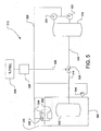
- FIGS 4-6 depict examples of several preferred means of refrigeration for use with the present invention.
- a system for dispensing pressurized gas 210 there is shown a system for dispensing pressurized gas 210.
- the system 210 is identical to the system 110 except that one specific embodiment of the refrigeration system 232 is shown in detail.
- pressurized gas source 112 in the system 110 is identical to the pressurized gas source 212 in the system 210.
- a refrigeration system 232 having a typical external refrigeration cycle (such as a hydrofluorocarbon cycle, for example, HCFC 134A) with a recirculating pump 234, a means to remove heat from the heat exchange fluid 236 and a heat exchanger 237.
- a typical external refrigeration cycle such as a hydrofluorocarbon cycle, for example, HCFC 134A
- pressurized gas source 112 in the system 110 is identical to the pressurized gas source 312 in the system 310.
- the pressurized gas source 312 is located either partially or entirely in a refrigerated container 340.
- Refrigeration is provided using a conventional refrigeration system 332 providing cold to air heat exchanger 338 located in the refrigerated container 340.
- the temperature in the container 340 is controlled by the electronic controller 328 using data from a temperature sensor 344.
- pressurized gas source 112 in the system 110 is identical to the pressurized gas source 412 in the system 410.
- a source of liquid hydrogen is used.
- the liquid hydrogen is stored in vessel 446.
- the liquid hydrogen is pumped using a cryogenic pump 448.
- Some of the hydrogen is pumped directly into a heat exchanger 450 where the liquid is warmed up to be converted to a gas and is and placed in the pressurized gas source 412.
- the rest of the hydrogen goes through a control valve 452, and into a cold storage device 454 that includes a heat exchanger, wherein the cold is stored in the cold storage device 454 until needed, wherein gas exiting the pressurized gas source 412 passes through the heat exchanger in the cold storage device 454 to cool the gas that will be delivered to the receiving tank 114.
- the cold storage device 454 preferably uses a condensable refrigerant to store the refrigeration until cooling is needed when filling the receiving tank.
- the temperature and pressure sensors may be based on calculated or estimated values rather than direct measurements from the receiving tank.
- the pressurized gas source of the various embodiments of the present invention may be a large volume storage tank, a pressurized gas supply line, a compressor discharge line, or any combination of these elements suitable for use in supplying gas to the receiving tank in an amount and at a pressure great enough to achieve a desired fill rate, fill level, and pressure in the receiving tank.
- a particularly preferred pressurized gas source for supplying pressurized gas to receiving tank is a system as shown and described in U.S. Pat. No. 5,351,726 (Diggins), which is fully incorporated by reference herein.
Landscapes
- Engineering & Computer Science (AREA)
- Mechanical Engineering (AREA)
- General Engineering & Computer Science (AREA)
- Filling Or Discharging Of Gas Storage Vessels (AREA)
- Pipeline Systems (AREA)
- Devices That Are Associated With Refrigeration Equipment (AREA)
Applications Claiming Priority (2)
| Application Number | Priority Date | Filing Date | Title |
|---|---|---|---|
| US75890 | 2002-02-14 | ||
| US10/075,890 US6619336B2 (en) | 2002-02-14 | 2002-02-14 | System and method for dispensing pressurized gas |
Publications (3)
| Publication Number | Publication Date |
|---|---|
| EP1336795A2 true EP1336795A2 (de) | 2003-08-20 |
| EP1336795A3 EP1336795A3 (de) | 2008-12-24 |
| EP1336795B1 EP1336795B1 (de) | 2010-03-31 |
Family
ID=27622777
Family Applications (1)
| Application Number | Title | Priority Date | Filing Date |
|---|---|---|---|
| EP03002915A Revoked EP1336795B1 (de) | 2002-02-14 | 2003-02-10 | Vorrichtung und Verfahren zum Befördern von Druckgas |
Country Status (9)
| Country | Link |
|---|---|
| US (1) | US6619336B2 (de) |
| EP (1) | EP1336795B1 (de) |
| JP (1) | JP4071648B2 (de) |
| AT (1) | ATE462923T1 (de) |
| CA (1) | CA2418588C (de) |
| DE (1) | DE60331877D1 (de) |
| DK (1) | DK1336795T3 (de) |
| ES (1) | ES2339434T3 (de) |
| PT (1) | PT1336795E (de) |
Cited By (12)
| Publication number | Priority date | Publication date | Assignee | Title |
|---|---|---|---|---|
| EP1806530A1 (de) * | 2005-12-06 | 2007-07-11 | Air Products and Chemicals, Inc. | Diagnoseverfahren und Vorrichtung für ein Druckgaszufuhrsystem |
| EP1693611A3 (de) * | 2005-02-17 | 2008-03-05 | Air Products and Chemicals, Inc. | Anlage und Verfahren zur Abgabe von Druckgas |
| EP1693612A3 (de) * | 2005-02-17 | 2010-05-05 | Air Products and Chemicals, Inc. | Anlage und Verfahren zur Abgabe von Druckgas |
| WO2011049466A1 (en) * | 2009-10-21 | 2011-04-28 | Statoil Asa | Method for the operation and control of gas filling |
| US8286670B2 (en) | 2007-06-22 | 2012-10-16 | L'air Liquide Societe Anonyme Pour L'etude Et L'exploitation Des Procedes Georges Claude | Method for controlled filling of pressurized gas tanks |
| WO2013014346A1 (fr) | 2011-07-22 | 2013-01-31 | L'air Liquide,Societe Anonyme Pour L'etude Et L'exploitation Des Procedes Georges Claude | Procédé de remplissage d'un réservoir avec du gaz sous pression |
| EP2796762A1 (de) * | 2013-04-22 | 2014-10-29 | Air Products and Chemicals, Inc. | Verfahren und System für temperaturgesteuerte Gasabgabe |
| US9605804B2 (en) * | 2010-04-21 | 2017-03-28 | Honda Motor Co., Ltd. | Method and system for tank refilling using active fueling speed control |
| FR3051882A1 (fr) * | 2016-05-24 | 2017-12-01 | L'air Liquide Sa Pour L'etude Et L'exploitation Des Procedes Georges Claude | Reservoir composite pour fluide sous pression |
| US10082247B1 (en) | 2017-05-22 | 2018-09-25 | Nel Hydrogen A/S | Method of refueling a hydrogen vehicle |
| US10288222B2 (en) | 2017-05-22 | 2019-05-14 | Nel Hydrogen A/S | Method of refueling a hydrogen vehicle |
| US11480303B2 (en) | 2015-08-30 | 2022-10-25 | Vasilios Manousiouthakis | Gas fueling systems and methods with minimum and/or no cooling |
Families Citing this family (86)
| Publication number | Priority date | Publication date | Assignee | Title |
|---|---|---|---|---|
| US7191602B2 (en) * | 2003-06-16 | 2007-03-20 | The Regents Of The University Of California | Storage of H2 by absorption and/or mixture within a fluid medium |
| US7402287B2 (en) * | 2004-12-17 | 2008-07-22 | Texaco Inc. | Apparatus and methods for producing hydrogen |
| US7354463B2 (en) * | 2004-12-17 | 2008-04-08 | Texaco Inc. | Apparatus and methods for producing hydrogen |
| US7892304B2 (en) * | 2004-12-17 | 2011-02-22 | Texaco Inc. | Apparatus and method for controlling compressor motor speed in a hydrogen generator |
| US7354464B2 (en) * | 2004-12-17 | 2008-04-08 | Texaco Inc. | Apparatus and method for producing hydrogen |
| US8156970B2 (en) * | 2005-10-10 | 2012-04-17 | Air Products And Chemicals, Inc. | Temperature-compensated dispensing of compressed gases |
| US20070079891A1 (en) * | 2005-10-10 | 2007-04-12 | Farese David J | Cascade bank selection based on ambient temperature |
| FR2896028B1 (fr) * | 2006-01-06 | 2008-07-04 | Air Liquide | Procede et dispositif de remplissage de conteneurs de gaz sous pression |
| US7484540B2 (en) * | 2006-01-27 | 2009-02-03 | Gm Global Technology Operations, Inc. | Liquid hydrogen storage tank with reduced tanking losses |
| JP4702078B2 (ja) * | 2006-02-03 | 2011-06-15 | トヨタ自動車株式会社 | エアサスペンション装置 |
| US20070186982A1 (en) * | 2006-02-10 | 2007-08-16 | Cohen Joseph P | Method for dispensing compressed gas |
| DE102006016554A1 (de) * | 2006-04-07 | 2007-10-11 | L'Air Liquide, S.A. a Directoire et Conseil de Surveillance pour l'Etude et l'Exploitation des Procédés Georges Claude | Verfahren zum Befüllen mindestens eines Druckgasbehälters mit mindestens einem Gas, Zwischenstück zum Verbinden mit einer Öffnung eines Druckgasbehälters und Druckgasflaschenarmatur |
| US7921883B2 (en) * | 2006-06-07 | 2011-04-12 | Air Products And Chemicals, Inc. | Hydrogen dispenser with user-selectable hydrogen dispensing rate algorithms |
| US8020589B2 (en) * | 2007-01-04 | 2011-09-20 | Air Products And Chemicals, Inc. | Hydrogen dispensing station and method of operating the same |
| DE102007012080A1 (de) * | 2007-03-13 | 2008-09-18 | Linde Ag | Verfahren zum Befüllen eines Wasserstoff-Speicherbehälters |
| JP4984991B2 (ja) * | 2007-03-14 | 2012-07-25 | トヨタ自動車株式会社 | ガス貯蔵システム |
| FR2920858B1 (fr) * | 2007-09-10 | 2009-11-27 | Air Liquide | Procede de remplissage de conteneur de gaz sous pression |
| US8365777B2 (en) * | 2008-02-20 | 2013-02-05 | Air Products And Chemicals, Inc. | Compressor fill method and apparatus |
| US7647194B1 (en) * | 2008-08-13 | 2010-01-12 | Daniel Glenn Casey | Method for calculating hydrogen temperature during vehicle fueling |
| US20100180983A1 (en) * | 2009-01-16 | 2010-07-22 | Ford Motor Company | Fueling system and method |
| JP5525188B2 (ja) * | 2009-06-09 | 2014-06-18 | 本田技研工業株式会社 | 水素充填装置及び水素充填方法 |
| JP5489573B2 (ja) * | 2009-07-30 | 2014-05-14 | トヨタ自動車株式会社 | ガス充填システム及びガス充填装置 |
| US8813497B2 (en) * | 2009-09-17 | 2014-08-26 | Echogen Power Systems, Llc | Automated mass management control |
| JP5345040B2 (ja) * | 2009-11-11 | 2013-11-20 | 三菱重工業株式会社 | 圧縮空気供給装置 |
| DE112010004411B4 (de) * | 2009-11-16 | 2017-10-19 | Toyota Jidosha Kabushiki Kaisha | Brenngasfüllverfahren |
| JP5328617B2 (ja) * | 2009-11-18 | 2013-10-30 | トヨタ自動車株式会社 | ガス充填システム、ガス充填方法、車両 |
| GB0922355D0 (en) | 2009-12-21 | 2010-02-03 | Linde Ag | Pressure vessel |
| JP5261408B2 (ja) * | 2010-01-25 | 2013-08-14 | トヨタ自動車株式会社 | 燃料ガスステーション、燃料ガス充填システム、燃料ガス供給方法 |
| US8783303B2 (en) | 2010-04-21 | 2014-07-22 | Ryan HARTY | Method and system for tank refilling |
| US9212783B2 (en) | 2010-04-21 | 2015-12-15 | Honda Motor Co., Ltd. | Method and system for tank refilling |
| US9347614B2 (en) | 2010-04-21 | 2016-05-24 | Honda Motor Co., Ltd. | Method and system for tank refilling using active fueling speed control |
| US9347612B2 (en) | 2010-04-21 | 2016-05-24 | Honda Motor Co., Ltd. | Method and system for tank refilling using active fueling speed control |
| US20120012225A1 (en) * | 2010-07-19 | 2012-01-19 | Marc Moszkowski | Method of filling CNG tanks |
| DE102010027683A1 (de) | 2010-07-20 | 2012-01-26 | Linde Aktiengesellschaft | Tankstelle mit Kommunikation |
| CN101975296A (zh) * | 2010-09-13 | 2011-02-16 | 武汉金鼎船舶工程设计有限公司 | 船用全自动气动快关阀控制装置 |
| US8656938B2 (en) * | 2010-11-29 | 2014-02-25 | GM Global Technology Operations LLC | Compressed gas tank system with fast fueling ability at any vessel pressure |
| US9618158B2 (en) | 2011-05-02 | 2017-04-11 | New Gas Industries, L.L.C. | Method and apparatus for compressing gas in a plurality of stages to a storage tank array having a plurality of storage tanks |
| US8899278B2 (en) | 2011-06-17 | 2014-12-02 | Air Products And Chemicals, Inc. | Pressure cycle management in compressed gas dispensing systems |
| US9234627B2 (en) * | 2011-07-08 | 2016-01-12 | Jose A. Cajiga | System, apparatus and method for the cold-weather storage of gaseous fuel |
| US8720500B2 (en) * | 2011-10-11 | 2014-05-13 | GM Global Technology Operations LLC | Electrical architecture for passive controller wake-up during refuel |
| US9284178B2 (en) | 2011-10-20 | 2016-03-15 | Rht Railhaul Technologies | Multi-fuel service station |
| PL2788215T3 (pl) * | 2011-12-07 | 2020-06-15 | Agility Fuel Systems Llc | Systemy i sposoby monitorowania i kontrolowania układów paliwowych |
| US9765930B2 (en) | 2012-01-31 | 2017-09-19 | J-W Power Company | CNG fueling system |
| US10018304B2 (en) | 2012-01-31 | 2018-07-10 | J-W Power Company | CNG fueling system |
| US10851944B2 (en) | 2012-01-31 | 2020-12-01 | J-W Power Company | CNG fueling system |
| US9261238B2 (en) | 2012-07-06 | 2016-02-16 | Air Products And Chemicals, Inc. | Method for dispensing a gas |
| CN104981646B (zh) * | 2012-08-24 | 2017-09-08 | 奥斯康普控股公司 | 虚拟气态燃料管道 |
| DE102013011052A1 (de) * | 2013-07-02 | 2015-01-08 | Linde Aktiengesellschaft | Verfahren zum Ermitteln eines Wasserstofftankdrucks |
| US9605805B2 (en) * | 2013-11-04 | 2017-03-28 | Trillium Transportation Fuels, Llc | Active pressure and flow regulation system |
| AU2014351040A1 (en) * | 2013-11-18 | 2016-06-02 | Mosaic Technology Development Pty Ltd | System and method for intelligent refuelling of a pressurised vessel |
| WO2015170670A1 (ja) | 2014-05-07 | 2015-11-12 | 日産自動車株式会社 | 燃料ガス充填システム及び燃料ガス充填方法 |
| JP6475445B2 (ja) * | 2014-09-11 | 2019-02-27 | 日立オートモティブシステムズメジャメント株式会社 | ガス充填装置及びその方法 |
| CN105889154A (zh) * | 2014-11-28 | 2016-08-24 | 陕西鼎基能源科技有限公司 | 高压气压力能等熵增压机 |
| SG11201707500YA (en) | 2015-03-13 | 2017-10-30 | Cenergy Solutions Inc | Increased storage capacity of gas in pressure vessels |
| JP2016176592A (ja) * | 2015-03-23 | 2016-10-06 | 株式会社日立プラントメカニクス | 水素プレクールシステム |
| WO2016179439A1 (en) * | 2015-05-05 | 2016-11-10 | Fanger Gary W | Dielectric heating of adsorbents to increase desorption rates |
| US10551001B2 (en) | 2015-09-03 | 2020-02-04 | J-W Power Company | Flow control system |
| US10077998B2 (en) | 2015-09-14 | 2018-09-18 | Honda Motor Co., Ltd. | Hydrogen fueling with integrity checks |
| CN105864634B (zh) * | 2016-05-18 | 2018-06-26 | 天津栢奕容科技发展有限公司 | 一种便携式氮气吹扫检漏抽真空充气设备及使用方法 |
| JP6652483B2 (ja) | 2016-11-07 | 2020-02-26 | 株式会社神戸製鋼所 | ガス供給システム及び水素供給設備 |
| US10059215B1 (en) * | 2017-03-08 | 2018-08-28 | A3 Labs, Llc | Energy source supply systems, energy source supply devices, and related methods |
| US10883663B2 (en) | 2018-05-24 | 2021-01-05 | Rolls-Royce North American Technologies Inc | Rapid fill container system |
| RU2703899C1 (ru) * | 2018-08-13 | 2019-10-22 | Акционерное общество "Государственный космический научно-производственный центр им. М.В. Хруничева" | Способ наполнения емкостей сжатым газом до требуемого давления и устройство для его реализации |
| US10961109B2 (en) | 2018-11-16 | 2021-03-30 | China Energy Investment Corporation Limited | Fluid bypass method and system for controlling the temperature of a non-petroleum fuel |
| US11009185B2 (en) | 2018-11-16 | 2021-05-18 | China Energy Investment Corporation Limited | Method and system of dispensing liquefied gas |
| US11313514B2 (en) | 2018-12-04 | 2022-04-26 | Honda Motor Co., Ltd. | Method and system for tank refueling using dispenser and nozzle readings |
| US11339926B2 (en) | 2018-12-05 | 2022-05-24 | Honda Motor Co., Ltd. | Methods and systems for improving hydrogen refueling |
| CN111023652A (zh) * | 2019-12-11 | 2020-04-17 | 广东电网有限责任公司 | 氦气循环冷却系统和设计方法、设备及存储介质 |
| KR20230051193A (ko) * | 2020-07-13 | 2023-04-17 | 아이비스 인크. | 수소 연료공급 시스템 및 방법 |
| US11796132B2 (en) | 2020-12-02 | 2023-10-24 | Green Grid Inc. | Hydrogen fuel storage and delivery system |
| US11649156B2 (en) | 2020-12-28 | 2023-05-16 | China Energy Investment Corporation Limited | System and method for pre-cooling fuel dispenser |
| JP7574648B2 (ja) * | 2021-01-08 | 2024-10-29 | トヨタ自動車株式会社 | 水素充填システム |
| US20230137335A1 (en) | 2021-10-29 | 2023-05-04 | Air Products And Chemicals, Inc. | Hydrogen storage and dispensing apparatus and method |
| KR20230091505A (ko) * | 2021-12-16 | 2023-06-23 | 현대자동차주식회사 | 충전 사양에 따른 가스 충전량을 확인가능한 가스 연료 기반의 이동체 및 이를 이용한 충전량 제공 방법 |
| US12092093B2 (en) | 2022-03-08 | 2024-09-17 | Air Products And Chemicals, Inc. | Apparatus and method for cryogenic pump cooldown |
| CN114688448B (zh) * | 2022-04-08 | 2023-11-10 | 四川华能氢能科技有限公司 | 一种基于氢气密度的电解制氢的氢气回收系统 |
| US11946599B2 (en) | 2022-06-08 | 2024-04-02 | Air Products And Chemicals, Inc. | Apparatus and method for hydrogen fuel dispensing |
| US20240353066A1 (en) | 2023-04-20 | 2024-10-24 | Air Products And Chemicals, Inc. | Apparatus and Method for Dispensing a Cryogenic Fluid |
| US12129165B1 (en) * | 2023-04-26 | 2024-10-29 | Air Products And Chemicals, Inc. | Apparatus and method for fuel dispensing nozzle maintenance or vehicle battery recharging nozzle maintenance |
| US20250075455A1 (en) | 2023-08-30 | 2025-03-06 | Air Products And Chemicals, Inc. | Apparatus and process for fog mitigation |
| US20250075858A1 (en) | 2023-08-30 | 2025-03-06 | Air Products And Chemicals, Inc. | Apparatus and process for cryogenic liquid vaporization to re-cool gas for cryogenic fluid recovery |
| US20250130554A1 (en) | 2023-10-24 | 2025-04-24 | Air Products And Chemicals, Inc. | Apparatus and process for controlling a display for fuel dispensing |
| US12497936B2 (en) | 2023-11-20 | 2025-12-16 | Air Products And Chemicals, Inc. | Apparatus and process for cooling pressurized gas for fueling |
| US12222073B1 (en) * | 2024-04-19 | 2025-02-11 | ZeroAvia, Inc. | Interrogation of temperature sensitive coatings on fuel tank exterior |
| US12613010B2 (en) | 2024-04-24 | 2026-04-28 | Air Products And Chemicals, Inc. | Apparatus, control system and process for rapid fuel dispensing |
| US20250332910A1 (en) | 2024-04-24 | 2025-10-30 | Air Products And Chemicals, Inc. | Apparatus, control system and process for rapid fuel dispensing |
Family Cites Families (19)
| Publication number | Priority date | Publication date | Assignee | Title |
|---|---|---|---|---|
| US3719196A (en) | 1970-05-06 | 1973-03-06 | Jones R Mc | Charging sequence system and process |
| US4515516A (en) | 1981-09-30 | 1985-05-07 | Champion, Perrine & Associates | Method and apparatus for compressing gases |
| US4527600A (en) | 1982-05-05 | 1985-07-09 | Rockwell International Corporation | Compressed natural gas dispensing system |
| DE3873653D1 (de) | 1987-07-23 | 1992-09-17 | Sulzer Ag | Einrichtung zum betanken eines gasbrennstoffbehaelters. |
| NZ229839A (en) | 1988-08-15 | 1992-01-29 | Sulzer Ag | Cng refueller with temperature and pressure cut-offs |
| US4984457A (en) | 1989-08-18 | 1991-01-15 | The United States Of America As Represented By The Administrator Of The National Aeronautics And Space Administration | Tank gauging apparatus and method |
| US5156198A (en) | 1991-02-20 | 1992-10-20 | Hall Gerald L | Pump lock fuel system |
| US5238030A (en) | 1991-06-27 | 1993-08-24 | Dvco | Method and apparatus for dispensing natural gas |
| US5259424A (en) | 1991-06-27 | 1993-11-09 | Dvco, Inc. | Method and apparatus for dispensing natural gas |
| US5169295A (en) | 1991-09-17 | 1992-12-08 | Tren.Fuels, Inc. | Method and apparatus for compressing gases with a liquid system |
| US5454408A (en) | 1993-08-11 | 1995-10-03 | Thermo Power Corporation | Variable-volume storage and dispensing apparatus for compressed natural gas |
| DE59404467D1 (de) * | 1993-11-08 | 1997-12-04 | Burckhardt Ag Maschf | Verfahren und Vorrichtung zum schnellen Betanken eines Druckbehälters mit einem gasförmigen Medium |
| US5488978A (en) * | 1994-05-02 | 1996-02-06 | Gas Research Institute | Apparatus and method for controlling the charging of NGV cylinders from natural gas refueling stations |
| JPH08100895A (ja) | 1994-09-30 | 1996-04-16 | Tokyo Gas Co Ltd | ガス供給装置 |
| US5628349A (en) | 1995-01-25 | 1997-05-13 | Pinnacle Cng Systems, Llc | System and method for dispensing pressurized gas |
| US5810058A (en) * | 1996-03-20 | 1998-09-22 | Gas Research Institute | Automated process and system for dispensing compressed natural gas |
| DE19705601A1 (de) * | 1997-02-14 | 1998-08-20 | Salzkotten Tankanlagen | Erdgas-Betankungsverfahren |
| US5868176A (en) * | 1997-05-27 | 1999-02-09 | Gas Research Institute | System for controlling the fill of compressed natural gas cylinders |
| US5970786A (en) * | 1997-09-25 | 1999-10-26 | Smith; Robert S. | Method for measuring compressed natural gas |
-
2002
- 2002-02-14 US US10/075,890 patent/US6619336B2/en not_active Expired - Lifetime
-
2003
- 2003-02-07 CA CA002418588A patent/CA2418588C/en not_active Expired - Lifetime
- 2003-02-10 EP EP03002915A patent/EP1336795B1/de not_active Revoked
- 2003-02-10 DK DK03002915.1T patent/DK1336795T3/da active
- 2003-02-10 ES ES03002915T patent/ES2339434T3/es not_active Expired - Lifetime
- 2003-02-10 AT AT03002915T patent/ATE462923T1/de active
- 2003-02-10 DE DE60331877T patent/DE60331877D1/de not_active Expired - Lifetime
- 2003-02-10 PT PT03002915T patent/PT1336795E/pt unknown
- 2003-02-14 JP JP2003036589A patent/JP4071648B2/ja not_active Expired - Lifetime
Cited By (14)
| Publication number | Priority date | Publication date | Assignee | Title |
|---|---|---|---|---|
| EP1693611A3 (de) * | 2005-02-17 | 2008-03-05 | Air Products and Chemicals, Inc. | Anlage und Verfahren zur Abgabe von Druckgas |
| EP1693612A3 (de) * | 2005-02-17 | 2010-05-05 | Air Products and Chemicals, Inc. | Anlage und Verfahren zur Abgabe von Druckgas |
| EP1806530A1 (de) * | 2005-12-06 | 2007-07-11 | Air Products and Chemicals, Inc. | Diagnoseverfahren und Vorrichtung für ein Druckgaszufuhrsystem |
| US7568507B2 (en) | 2005-12-06 | 2009-08-04 | Air Products And Chemicals, Inc. | Diagnostic method and apparatus for a pressurized gas supply system |
| US8286670B2 (en) | 2007-06-22 | 2012-10-16 | L'air Liquide Societe Anonyme Pour L'etude Et L'exploitation Des Procedes Georges Claude | Method for controlled filling of pressurized gas tanks |
| WO2011049466A1 (en) * | 2009-10-21 | 2011-04-28 | Statoil Asa | Method for the operation and control of gas filling |
| US9605804B2 (en) * | 2010-04-21 | 2017-03-28 | Honda Motor Co., Ltd. | Method and system for tank refilling using active fueling speed control |
| WO2013014346A1 (fr) | 2011-07-22 | 2013-01-31 | L'air Liquide,Societe Anonyme Pour L'etude Et L'exploitation Des Procedes Georges Claude | Procédé de remplissage d'un réservoir avec du gaz sous pression |
| EP2796762A1 (de) * | 2013-04-22 | 2014-10-29 | Air Products and Chemicals, Inc. | Verfahren und System für temperaturgesteuerte Gasabgabe |
| US9279541B2 (en) | 2013-04-22 | 2016-03-08 | Air Products And Chemicals, Inc. | Method and system for temperature-controlled gas dispensing |
| US11480303B2 (en) | 2015-08-30 | 2022-10-25 | Vasilios Manousiouthakis | Gas fueling systems and methods with minimum and/or no cooling |
| FR3051882A1 (fr) * | 2016-05-24 | 2017-12-01 | L'air Liquide Sa Pour L'etude Et L'exploitation Des Procedes Georges Claude | Reservoir composite pour fluide sous pression |
| US10082247B1 (en) | 2017-05-22 | 2018-09-25 | Nel Hydrogen A/S | Method of refueling a hydrogen vehicle |
| US10288222B2 (en) | 2017-05-22 | 2019-05-14 | Nel Hydrogen A/S | Method of refueling a hydrogen vehicle |
Also Published As
| Publication number | Publication date |
|---|---|
| ES2339434T3 (es) | 2010-05-20 |
| PT1336795E (pt) | 2010-06-29 |
| US6619336B2 (en) | 2003-09-16 |
| EP1336795B1 (de) | 2010-03-31 |
| DK1336795T3 (da) | 2010-07-12 |
| CA2418588A1 (en) | 2003-08-14 |
| JP2003301999A (ja) | 2003-10-24 |
| US20030150510A1 (en) | 2003-08-14 |
| DE60331877D1 (de) | 2010-05-12 |
| JP4071648B2 (ja) | 2008-04-02 |
| CA2418588C (en) | 2005-11-08 |
| EP1336795A3 (de) | 2008-12-24 |
| ATE462923T1 (de) | 2010-04-15 |
Similar Documents
| Publication | Publication Date | Title |
|---|---|---|
| US6619336B2 (en) | System and method for dispensing pressurized gas | |
| US5628349A (en) | System and method for dispensing pressurized gas | |
| US7152637B2 (en) | Method and apparatus for dispensing compressed gas | |
| US5570729A (en) | Method and apparatus for the rapid tanking of a pressure container with a gaseous medium | |
| US20070186982A1 (en) | Method for dispensing compressed gas | |
| US8360112B2 (en) | Method and device for filling pressure gas containers | |
| US7178565B2 (en) | Self-contained mobile fueling station | |
| US8517062B2 (en) | Method for filling a pressurized gas container | |
| EP3759564B1 (de) | Mobiler wasserstoffspender für brennstoffzellenfahrzeuge | |
| KR20220085830A (ko) | 누출 감지 | |
| US20060180237A1 (en) | System and method for dispensing compressed gas | |
| US12152736B2 (en) | System and method for compressed gas dispensing with subsequent venting | |
| MXPA97005499A (en) | System and method to remove gas pressuriz | |
| JP2026500949A (ja) | ガス燃料を貯蔵するためのタンク装置を作動させる方法、およびガス燃料を貯蔵するためのタンク装置 | |
| JP2017044217A (ja) | ガス充填装置 |
Legal Events
| Date | Code | Title | Description |
|---|---|---|---|
| PUAI | Public reference made under article 153(3) epc to a published international application that has entered the european phase |
Free format text: ORIGINAL CODE: 0009012 |
|
| AK | Designated contracting states |
Designated state(s): AT BE BG CH CY CZ DE DK EE ES FI FR GB GR HU IE IT LI LU MC NL PT SE SI SK TR |
|
| AX | Request for extension of the european patent |
Extension state: AL LT LV MK RO |
|
| PUAL | Search report despatched |
Free format text: ORIGINAL CODE: 0009013 |
|
| AK | Designated contracting states |
Kind code of ref document: A3 Designated state(s): AT BE BG CH CY CZ DE DK EE ES FI FR GB GR HU IE IT LI LU MC NL PT SE SI SK TR |
|
| AX | Request for extension of the european patent |
Extension state: AL LT LV MK RO |
|
| 17P | Request for examination filed |
Effective date: 20090220 |
|
| 17Q | First examination report despatched |
Effective date: 20090317 |
|
| AKX | Designation fees paid |
Designated state(s): AT BE BG CH CY CZ DE DK EE ES FI FR GB GR HU IE IT LI LU MC NL PT SE SI SK TR |
|
| GRAP | Despatch of communication of intention to grant a patent |
Free format text: ORIGINAL CODE: EPIDOSNIGR1 |
|
| RIC1 | Information provided on ipc code assigned before grant |
Ipc: F17C 7/00 20060101AFI20090924BHEP |
|
| GRAS | Grant fee paid |
Free format text: ORIGINAL CODE: EPIDOSNIGR3 |
|
| GRAA | (expected) grant |
Free format text: ORIGINAL CODE: 0009210 |
|
| STAA | Information on the status of an ep patent application or granted ep patent |
Free format text: STATUS: THE PATENT HAS BEEN GRANTED |
|
| AK | Designated contracting states |
Kind code of ref document: B1 Designated state(s): AT BE BG CH CY CZ DE DK EE ES FI FR GB GR HU IE IT LI LU MC NL PT SE SI SK TR |
|
| REG | Reference to a national code |
Ref country code: CH Ref legal event code: EP Ref country code: GB Ref legal event code: FG4D Ref country code: CH Ref legal event code: NV Representative=s name: E. BLUM & CO. AG PATENT- UND MARKENANWAELTE VSP |
|
| REG | Reference to a national code |
Ref country code: NL Ref legal event code: T3 |
|
| REG | Reference to a national code |
Ref country code: IE Ref legal event code: FG4D |
|
| REF | Corresponds to: |
Ref document number: 60331877 Country of ref document: DE Date of ref document: 20100512 Kind code of ref document: P |
|
| REG | Reference to a national code |
Ref country code: GR Ref legal event code: EP Ref document number: 20100401018 Country of ref document: GR |
|
| REG | Reference to a national code |
Ref country code: ES Ref legal event code: FG2A Ref document number: 2339434 Country of ref document: ES Kind code of ref document: T3 |
|
| REG | Reference to a national code |
Ref country code: SE Ref legal event code: TRGR |
|
| REG | Reference to a national code |
Ref country code: PT Ref legal event code: SC4A Free format text: AVAILABILITY OF NATIONAL TRANSLATION Effective date: 20100622 |
|
| REG | Reference to a national code |
Ref country code: DK Ref legal event code: T3 |
|
| REG | Reference to a national code |
Ref country code: SK Ref legal event code: T3 Ref document number: E 7217 Country of ref document: SK |
|
| PG25 | Lapsed in a contracting state [announced via postgrant information from national office to epo] |
Ref country code: SI Free format text: LAPSE BECAUSE OF FAILURE TO SUBMIT A TRANSLATION OF THE DESCRIPTION OR TO PAY THE FEE WITHIN THE PRESCRIBED TIME-LIMIT Effective date: 20100331 Ref country code: FI Free format text: LAPSE BECAUSE OF FAILURE TO SUBMIT A TRANSLATION OF THE DESCRIPTION OR TO PAY THE FEE WITHIN THE PRESCRIBED TIME-LIMIT Effective date: 20100331 |
|
| PG25 | Lapsed in a contracting state [announced via postgrant information from national office to epo] |
Ref country code: CY Free format text: LAPSE BECAUSE OF FAILURE TO SUBMIT A TRANSLATION OF THE DESCRIPTION OR TO PAY THE FEE WITHIN THE PRESCRIBED TIME-LIMIT Effective date: 20100331 Ref country code: EE Free format text: LAPSE BECAUSE OF FAILURE TO SUBMIT A TRANSLATION OF THE DESCRIPTION OR TO PAY THE FEE WITHIN THE PRESCRIBED TIME-LIMIT Effective date: 20100331 |
|
| PLBI | Opposition filed |
Free format text: ORIGINAL CODE: 0009260 |
|
| 26 | Opposition filed |
Opponent name: L'AIR LIQUIDE, SOCIETE ANONYME P Effective date: 20101125 |
|
| PLAX | Notice of opposition and request to file observation + time limit sent |
Free format text: ORIGINAL CODE: EPIDOSNOBS2 |
|
| REG | Reference to a national code |
Ref country code: HU Ref legal event code: AG4A Ref document number: E010040 Country of ref document: HU |
|
| PLAF | Information modified related to communication of a notice of opposition and request to file observations + time limit |
Free format text: ORIGINAL CODE: EPIDOSCOBS2 |
|
| PLAF | Information modified related to communication of a notice of opposition and request to file observations + time limit |
Free format text: ORIGINAL CODE: EPIDOSCOBS2 |
|
| PLBB | Reply of patent proprietor to notice(s) of opposition received |
Free format text: ORIGINAL CODE: EPIDOSNOBS3 |
|
| PG25 | Lapsed in a contracting state [announced via postgrant information from national office to epo] |
Ref country code: MC Free format text: LAPSE BECAUSE OF NON-PAYMENT OF DUE FEES Effective date: 20110228 |
|
| PG25 | Lapsed in a contracting state [announced via postgrant information from national office to epo] |
Ref country code: LU Free format text: LAPSE BECAUSE OF NON-PAYMENT OF DUE FEES Effective date: 20110210 |
|
| PG25 | Lapsed in a contracting state [announced via postgrant information from national office to epo] |
Ref country code: BG Free format text: LAPSE BECAUSE OF FAILURE TO SUBMIT A TRANSLATION OF THE DESCRIPTION OR TO PAY THE FEE WITHIN THE PRESCRIBED TIME-LIMIT Effective date: 20100630 |
|
| REG | Reference to a national code |
Ref country code: FR Ref legal event code: PLFP Year of fee payment: 14 |
|
| REG | Reference to a national code |
Ref country code: FR Ref legal event code: PLFP Year of fee payment: 15 |
|
| APBM | Appeal reference recorded |
Free format text: ORIGINAL CODE: EPIDOSNREFNO |
|
| APBP | Date of receipt of notice of appeal recorded |
Free format text: ORIGINAL CODE: EPIDOSNNOA2O |
|
| APAH | Appeal reference modified |
Free format text: ORIGINAL CODE: EPIDOSCREFNO |
|
| APBM | Appeal reference recorded |
Free format text: ORIGINAL CODE: EPIDOSNREFNO |
|
| APBP | Date of receipt of notice of appeal recorded |
Free format text: ORIGINAL CODE: EPIDOSNNOA2O |
|
| APBQ | Date of receipt of statement of grounds of appeal recorded |
Free format text: ORIGINAL CODE: EPIDOSNNOA3O |
|
| APBQ | Date of receipt of statement of grounds of appeal recorded |
Free format text: ORIGINAL CODE: EPIDOSNNOA3O |
|
| REG | Reference to a national code |
Ref country code: FR Ref legal event code: PLFP Year of fee payment: 16 |
|
| PLAB | Opposition data, opponent's data or that of the opponent's representative modified |
Free format text: ORIGINAL CODE: 0009299OPPO |
|
| R26 | Opposition filed (corrected) |
Opponent name: L'AIR LIQUIDE, SOCIETE ANONYME POUR L'ETUDE ET L'EXPLOITATION DES PROCEDES GEORGES CLAUDE Effective date: 20101125 |
|
| PGFP | Annual fee paid to national office [announced via postgrant information from national office to epo] |
Ref country code: SE Payment date: 20211210 Year of fee payment: 20 Ref country code: SK Payment date: 20211224 Year of fee payment: 20 Ref country code: GB Payment date: 20211223 Year of fee payment: 20 Ref country code: IE Payment date: 20211209 Year of fee payment: 20 Ref country code: FR Payment date: 20211217 Year of fee payment: 20 |
|
| PGFP | Annual fee paid to national office [announced via postgrant information from national office to epo] |
Ref country code: NL Payment date: 20211216 Year of fee payment: 20 Ref country code: CH Payment date: 20211216 Year of fee payment: 20 |
|
| PGFP | Annual fee paid to national office [announced via postgrant information from national office to epo] |
Ref country code: HU Payment date: 20220109 Year of fee payment: 20 Ref country code: DK Payment date: 20220209 Year of fee payment: 20 Ref country code: DE Payment date: 20211214 Year of fee payment: 20 Ref country code: AT Payment date: 20220125 Year of fee payment: 20 |
|
| PGFP | Annual fee paid to national office [announced via postgrant information from national office to epo] |
Ref country code: TR Payment date: 20220209 Year of fee payment: 20 Ref country code: PT Payment date: 20220210 Year of fee payment: 20 Ref country code: IT Payment date: 20220111 Year of fee payment: 20 Ref country code: GR Payment date: 20220120 Year of fee payment: 20 Ref country code: ES Payment date: 20220303 Year of fee payment: 20 Ref country code: CZ Payment date: 20220118 Year of fee payment: 20 Ref country code: BE Payment date: 20220118 Year of fee payment: 20 |
|
| APBU | Appeal procedure closed |
Free format text: ORIGINAL CODE: EPIDOSNNOA9O |
|
| REG | Reference to a national code |
Ref country code: DE Ref legal event code: R071 Ref document number: 60331877 Country of ref document: DE |
|
| REG | Reference to a national code |
Ref country code: DK Ref legal event code: EUP Expiry date: 20230210 |
|
| REG | Reference to a national code |
Ref country code: CH Ref legal event code: PL Ref country code: NL Ref legal event code: MK Effective date: 20230209 |
|
| REG | Reference to a national code |
Ref country code: BE Ref legal event code: MK Effective date: 20230210 |
|
| REG | Reference to a national code |
Ref country code: GB Ref legal event code: PE20 Expiry date: 20230209 |
|
| REG | Reference to a national code |
Ref country code: SK Ref legal event code: MK4A Ref document number: E 7217 Country of ref document: SK Expiry date: 20230210 Ref country code: AT Ref legal event code: MK07 Ref document number: 462923 Country of ref document: AT Kind code of ref document: T Effective date: 20230210 |
|
| REG | Reference to a national code |
Ref country code: SE Ref legal event code: EUG |
|
| REG | Reference to a national code |
Ref country code: IE Ref legal event code: MK9A |
|
| REG | Reference to a national code |
Ref country code: ES Ref legal event code: FD2A Effective date: 20230426 |
|
| PG25 | Lapsed in a contracting state [announced via postgrant information from national office to epo] |
Ref country code: PT Free format text: LAPSE BECAUSE OF EXPIRATION OF PROTECTION Effective date: 20230220 Ref country code: IE Free format text: LAPSE BECAUSE OF EXPIRATION OF PROTECTION Effective date: 20230210 Ref country code: CZ Free format text: LAPSE BECAUSE OF EXPIRATION OF PROTECTION Effective date: 20230210 |
|
| PG25 | Lapsed in a contracting state [announced via postgrant information from national office to epo] |
Ref country code: SK Free format text: LAPSE BECAUSE OF EXPIRATION OF PROTECTION Effective date: 20230210 Ref country code: GB Free format text: LAPSE BECAUSE OF EXPIRATION OF PROTECTION Effective date: 20230209 |
|
| PLAY | Examination report in opposition despatched + time limit |
Free format text: ORIGINAL CODE: EPIDOSNORE2 |
|
| PG25 | Lapsed in a contracting state [announced via postgrant information from national office to epo] |
Ref country code: ES Free format text: LAPSE BECAUSE OF EXPIRATION OF PROTECTION Effective date: 20230211 |
|
| PLBC | Reply to examination report in opposition received |
Free format text: ORIGINAL CODE: EPIDOSNORE3 |
|
| PLAY | Examination report in opposition despatched + time limit |
Free format text: ORIGINAL CODE: EPIDOSNORE2 |
|
| RDAF | Communication despatched that patent is revoked |
Free format text: ORIGINAL CODE: EPIDOSNREV1 |
|
| STAA | Information on the status of an ep patent application or granted ep patent |
Free format text: STATUS: THE PATENT HAS BEEN GRANTED |
|
| REG | Reference to a national code |
Ref country code: DE Ref legal event code: R064 Ref document number: 60331877 Country of ref document: DE Ref country code: DE Ref legal event code: R103 Ref document number: 60331877 Country of ref document: DE |
|
| RDAG | Patent revoked |
Free format text: ORIGINAL CODE: 0009271 |
|
| STAA | Information on the status of an ep patent application or granted ep patent |
Free format text: STATUS: PATENT REVOKED |
|
| REG | Reference to a national code |
Ref country code: CH Ref legal event code: N12 Free format text: ST27 STATUS EVENT CODE: U-0-0-N10-N12 (AS PROVIDED BY THE NATIONAL OFFICE) Effective date: 20260121 |
|
| 27W | Patent revoked |
Effective date: 20251013 |
|
| REG | Reference to a national code |
Ref country code: SK Ref legal event code: MC4A Ref document number: E 7217 Country of ref document: SK Effective date: 20251013 |