EP1337450B1 - Aiguillage de transport destine a une voie de transport de materiau en forme de panneau, notamment une voie de transport de verre plat - Google Patents
Aiguillage de transport destine a une voie de transport de materiau en forme de panneau, notamment une voie de transport de verre plat Download PDFInfo
- Publication number
- EP1337450B1 EP1337450B1 EP01992680A EP01992680A EP1337450B1 EP 1337450 B1 EP1337450 B1 EP 1337450B1 EP 01992680 A EP01992680 A EP 01992680A EP 01992680 A EP01992680 A EP 01992680A EP 1337450 B1 EP1337450 B1 EP 1337450B1
- Authority
- EP
- European Patent Office
- Prior art keywords
- transport
- branch
- glass
- conveyor line
- conveyor
- Prior art date
- Legal status (The legal status is an assumption and is not a legal conclusion. Google has not performed a legal analysis and makes no representation as to the accuracy of the status listed.)
- Expired - Lifetime
Links
- 239000000463 material Substances 0.000 title claims abstract description 9
- 239000005357 flat glass Substances 0.000 title description 8
- 239000011521 glass Substances 0.000 description 47
- 238000004519 manufacturing process Methods 0.000 description 6
- 238000005520 cutting process Methods 0.000 description 4
- 238000010276 construction Methods 0.000 description 2
- 230000007547 defect Effects 0.000 description 2
- 230000001360 synchronised effect Effects 0.000 description 2
- 230000001133 acceleration Effects 0.000 description 1
- 238000009826 distribution Methods 0.000 description 1
- 238000007689 inspection Methods 0.000 description 1
- 230000003287 optical effect Effects 0.000 description 1
- 238000005457 optimization Methods 0.000 description 1
- 230000001737 promoting effect Effects 0.000 description 1
- 238000011144 upstream manufacturing Methods 0.000 description 1
- 239000002699 waste material Substances 0.000 description 1
Images

Classifications
-
- B—PERFORMING OPERATIONS; TRANSPORTING
- B65—CONVEYING; PACKING; STORING; HANDLING THIN OR FILAMENTARY MATERIAL
- B65G—TRANSPORT OR STORAGE DEVICES, e.g. CONVEYORS FOR LOADING OR TIPPING, SHOP CONVEYOR SYSTEMS OR PNEUMATIC TUBE CONVEYORS
- B65G13/00—Roller-ways
- B65G13/08—Roller-ways of curved form; with branch-offs
- B65G13/10—Switching arrangements
-
- B—PERFORMING OPERATIONS; TRANSPORTING
- B65—CONVEYING; PACKING; STORING; HANDLING THIN OR FILAMENTARY MATERIAL
- B65G—TRANSPORT OR STORAGE DEVICES, e.g. CONVEYORS FOR LOADING OR TIPPING, SHOP CONVEYOR SYSTEMS OR PNEUMATIC TUBE CONVEYORS
- B65G47/00—Article or material-handling devices associated with conveyors; Methods employing such devices
- B65G47/52—Devices for transferring articles or materials between conveyors i.e. discharging or feeding devices
- B65G47/64—Switching conveyors
- B65G47/641—Switching conveyors by a linear displacement of the switching conveyor
- B65G47/643—Switching conveyors by a linear displacement of the switching conveyor in a vertical plane
-
- B—PERFORMING OPERATIONS; TRANSPORTING
- B65—CONVEYING; PACKING; STORING; HANDLING THIN OR FILAMENTARY MATERIAL
- B65G—TRANSPORT OR STORAGE DEVICES, e.g. CONVEYORS FOR LOADING OR TIPPING, SHOP CONVEYOR SYSTEMS OR PNEUMATIC TUBE CONVEYORS
- B65G49/00—Conveying systems characterised by their application for specified purposes not otherwise provided for
- B65G49/05—Conveying systems characterised by their application for specified purposes not otherwise provided for for fragile or damageable materials or articles
- B65G49/06—Conveying systems characterised by their application for specified purposes not otherwise provided for for fragile or damageable materials or articles for fragile sheets, e.g. glass
- B65G49/063—Transporting devices for sheet glass
- B65G49/064—Transporting devices for sheet glass in a horizontal position
Definitions
- the invention relates to a transfer switch for a Conveyor line for plate material suitable for roller conveyors.
- the invention is used as a transport switch for a flat glass conveyor line application.
- the invention can but also for conveyor lines for other plate materials Find application, for example in the construction area for plasterboard, which is similar to flat glass on a production line produced as a continuous plate belt and then divided into individual plate formats by cutting become.
- the glass runs in continuously Form a band several meters wide from the glass furnace and arrives on a conveyor line that the flat glass belt with defined conveying speed synchronous to the production of glass strips at the furnace outlet.
- These include conveyor lines from the area where the glass ribbon has cooled sufficiently roller conveyors.
- the conveyor line is initially synchronous with the continuous conveying movement of the glass ribbon that optical inspection of the glass for defects such as inclusions, gas bubbles etc., and their marking, as well as cross cutting of the glass ribbon, usually under computer control in different Formats, as well as the longitudinal scribing of through Cross cutting manufactured glass panels.
- Through acceleration sections In the conveyor line distances between the successive ones created by cross cutting Glass panels produced.
- such transport switches are designed as conveyor sections of a roller conveyor, between a horizontal operating position, in which they put the arriving glass panels on the same Forward level conveyor branch, and one pivoted into an inclined position around the upstream end ramp-like position switchable, in which it the arriving glass panels like a ramp on the upper conveyor branch redirect.
- a second problem is that the Transport switches due to the limited possible steepness the ramp-shaped position a corresponding length in Must have transport direction and switch between the two positions is only possible after an incoming Glass panel has completely passed the switch. This applies in particular to the swinging up into the ramp-like Position. Including those required for switching Time means that the distance between successive Glass panels on the conveyor line larger than that The length of the transport switch must be.
- the invention has for its object an improved To create transport switch, both problems more conventional Avoids transport switches, namely sudden stresses excludes the glass panels and thus the risk of damage or the glass breakage and on the other hand shorter ones Distances of the successive on the transport route Glass panels made possible than the conventional ones Transport switches is the case.
- the task applies accordingly also for a transport switch for other board materials as flat glass, for example plasterboard, the mechanically are sensitive and similar problems in promoting them occur.
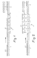
- the drawings show a flat glass conveyor line in side view, with a feed branch 1, a first discharge branch 2 in the plane of the feed branch 1, and a second Discharge branch 3, which is parallel to the first discharge branch 2 is arranged to this, the two discharge branches 2 and 3 are aligned with the feed branch 1 in the transport direction, and with one between the feed branch 1 and the discharge branches 2, 3 arranged transport switch 4. Also three consecutively transported on the conveyor line Glass panels G1, G2, G3 drawn to the mode of operation of the To make the transport switch clear. The glass panel G1 should be directed to the lower branch 2, the following Glass plate G2 is to be redirected to the upper discharge branch 3 and the following glass panel G3 should again get to the lower discharge branch 2.
- Figure 1 shows the conveyor line with the transport switch 4 in their one operating position, in which they the feed branch 1 with the lower discharge branch lying on the same level 2 connects.
- the distances are between the successive glass panels G1, G2, G3 clearly less than the length L of the transport switch 4.
- the conveying direction is marked by an arrow.
- the first one Glass panel G1 already has the transport switch 4 for the most part passes and runs on the lower discharge branch 2. Die the next following glass panel G2 is already partially on the transport switch 4; you follow the next glass plate G3 on the feed branch 2.
- Figure 2 shows the position of the transport switch 4 in the other Operating position in which the second glass sheet G2, while remaining in a horizontal position, to the level of the upper discharge branch 3 is raised and continue to run on it can.
- Figure 2 also shows the construction of the transport switch 4 clearly. It consists of a number of in the direction of transport successive short roller conveyor segments 41, 42, 43, 44, 45, 46, each in the drawings are symbolically represented by a conveyor roller, and the individually and independently of each other between the lower Position (Figure 1) and the upper position ( Figure 2) can be raised are lowerable.
- These liftable turnout segments 41 to 46 can, as shown in the drawings, alternately with fixed short roller conveyor sections 47 may be arranged or in immediate succession. They each include driven conveyor rollers, so that the transport movement one on the transport switch located glass plate, here the glass plate G2, too continuously during the lifting of the transport switch segments goes on.
- the lifting and lowering of the transport switch segments 41 to 46 takes place under computer control in synchronization with the transport of the Glass panels on the conveyor line and, if necessary, taking into account the size of the individual glass panels or their Length in the conveying direction.
- the lifting switch segments 41 to 46 are lifted simultaneously and synchronously as soon as the glass sheet in question G2 is largely or to a sufficient extent on the transport switch area to be able to be lifted.
- FIGS. 3A to 3C show highlights three phases of the return of the transfer switch in the lower position during the further movement of the glass panels on the conveyor line.
- 3B and 3C show like the next glass sheet G3 already in the transport switch area runs in while the outlet is still on the upper discharge branch 3 redirected glass sheet G2 from the transport switch area is underway.
Landscapes
- Engineering & Computer Science (AREA)
- Mechanical Engineering (AREA)
- Branching, Merging, And Special Transfer Between Conveyors (AREA)
- Relays Between Conveyors (AREA)
- Joining Of Glass To Other Materials (AREA)
Claims (1)
- Aiguillage de transport destiné à une voie de transport de matériau en forme de panneau, pour transférer le flux de transport de matériau en plaque d'une voie d'entrée (1) de la voie de transport vers au moins deux voies de sortie (2, 3) qui sont alignées avec la voie d'entrée (1) dans la direction de transport et parmi lesquelles l'une des voies de sortie (2) est située dans le même plan que la voie d'entrée (1) et l'autre voie de sortie (3) est située dans un plan décalé en hauteur par rapport à celle-ci, l'aiguillage de transport (4) étant formé d'une pluralité de segments de voie de transport (41 à 46) de faible longueur disposés les uns à la suite des autre dans la direction de transport, qui peuvent être déplacés individuellement entre le niveau de la première voie de sortie (2) et le niveau de la deuxième voie de sortie (3), lesdits segments, pour transférer un panneau de la voie d'entrée (1) sur la voie de sortie (3) décalée en hauteur, pouvant être déplacés en hauteur ensemble et de manière synchronisée et ramenés de manière synchronisée avec l'avance du panneau sur la voie de sortie (3) décalée en hauteur, individuellement, l'un après l'autre, au niveau de la voie d'entrée (1).
Applications Claiming Priority (3)
| Application Number | Priority Date | Filing Date | Title |
|---|---|---|---|
| DE10053852 | 2000-10-30 | ||
| DE10053852A DE10053852A1 (de) | 2000-10-30 | 2000-10-30 | Transportweiche für Plattenmaterial-Förderstrecke, insbesondere Flachglas-Förderstrecke |
| PCT/DE2001/004057 WO2002036467A1 (fr) | 2000-10-30 | 2001-10-30 | Aiguillage de transport destine a une voie de transport de materiau en forme de panneau, notamment une voie de transport de verre plat |
Publications (2)
| Publication Number | Publication Date |
|---|---|
| EP1337450A1 EP1337450A1 (fr) | 2003-08-27 |
| EP1337450B1 true EP1337450B1 (fr) | 2004-04-14 |
Family
ID=7661607
Family Applications (1)
| Application Number | Title | Priority Date | Filing Date |
|---|---|---|---|
| EP01992680A Expired - Lifetime EP1337450B1 (fr) | 2000-10-30 | 2001-10-30 | Aiguillage de transport destine a une voie de transport de materiau en forme de panneau, notamment une voie de transport de verre plat |
Country Status (6)
| Country | Link |
|---|---|
| US (1) | US6669003B2 (fr) |
| EP (1) | EP1337450B1 (fr) |
| AT (1) | ATE264247T1 (fr) |
| CA (1) | CA2395860A1 (fr) |
| DE (2) | DE10053852A1 (fr) |
| WO (1) | WO2002036467A1 (fr) |
Families Citing this family (15)
| Publication number | Priority date | Publication date | Assignee | Title |
|---|---|---|---|---|
| US7296673B2 (en) * | 2005-06-10 | 2007-11-20 | Applied Materials, Inc. | Substrate conveyor system |
| US7284651B2 (en) * | 2005-06-20 | 2007-10-23 | Durr Systems, Inc. | Conveyor system and method of conveying elements |
| US7497317B2 (en) * | 2005-11-02 | 2009-03-03 | Chunghwa Picture Tubes, Ltd. | Apparatus for conveying and raising objects |
| DE102006039697B4 (de) * | 2006-08-21 | 2010-07-29 | SSI Schäfer Noell GmbH Lager- und Systemtechnik | Vorrichtung und Verfahren zum Entladen von mit Palettenlagen beladenen Tablaren |
| DE102007058786B3 (de) * | 2007-12-06 | 2009-01-29 | Grenzebach Maschinenbau Gmbh | Vorrichtung und Verfahren zum Ausleiten von Glasplatten in einer Fertigungslinie sowie Computerprogramm und maschinenlesbarer Träger dafür |
| US8826851B2 (en) * | 2008-07-17 | 2014-09-09 | Oberlikon Solar AG, Trubbach | Cover for a roller |
| CN102009840B (zh) * | 2010-11-10 | 2012-08-01 | 友达光电股份有限公司 | 输送装置 |
| EP2870089A4 (fr) * | 2012-07-05 | 2016-04-27 | Laitram Llc | Dispositif de déviation à spirale rotative |
| DE102013102843B4 (de) * | 2013-03-20 | 2016-03-17 | Elopak Systems Ag | Verfahren und Vorrichtung zum Abtransportieren von Packungsbehältern |
| ITUB20152553A1 (it) * | 2015-07-28 | 2017-01-28 | Biesse Spa | Procedimento di lavorazione di lastre di vetro, pietra, marmo o simili, di grandi dimensioni in un centro di lavoro a controllo numerico |
| US9745137B1 (en) * | 2016-06-03 | 2017-08-29 | Zme, Llc | Apparatus, system and method for material handling and/or processing |
| DE102018133052A1 (de) * | 2018-12-20 | 2020-06-25 | Deutsche Post Ag | Stetigförderer zum Fördern von Objekten und Objektförderhalle mit Stetigförderer |
| CN113320880A (zh) * | 2021-06-08 | 2021-08-31 | 北京七星华创集成电路装备有限公司 | 液晶面板卡夹的传送组件、液晶面板制造设备 |
| CN115520621B (zh) * | 2022-09-13 | 2024-09-24 | 高安罗斯福陶瓷有限公司 | 一种带高度差输送的瓷砖输送设备 |
| DE102022128965B4 (de) * | 2022-11-02 | 2026-04-30 | Amova Gmbh | Querförderer für Rollgänge |
Family Cites Families (19)
| Publication number | Priority date | Publication date | Assignee | Title |
|---|---|---|---|---|
| US2693135A (en) * | 1949-03-15 | 1954-11-02 | Stimson Lumber Company | Hot plate press loader |
| US2856055A (en) * | 1954-05-10 | 1958-10-14 | Petersen Oven Co | Tunnel oven unloader |
| US2921663A (en) * | 1956-05-16 | 1960-01-19 | Coe Mfg Co | Sheet handling apparatus |
| US3169630A (en) * | 1962-04-16 | 1965-02-16 | Western Electric Co | Conveyor mechanism |
| US3194417A (en) * | 1964-08-03 | 1965-07-13 | Libbey Owens Ford Glass Co | Method and apparatus for transferring sheets from a first conveyor to a second conveyor |
| DE2040879C3 (de) * | 1970-08-18 | 1974-01-17 | Alfred 2000 Hamburg Wriedt | Vorrichtung zum Bewegen von Gegenständen mittels mehrerer an Unterdruck angeschlossener Förderrollen |
| DE2041686C3 (de) * | 1970-08-21 | 1973-11-29 | Guenter 7421 Mehrstetten Stumpf | Fordermagazin |
| US4047625A (en) * | 1974-05-21 | 1977-09-13 | Willson Barrat David Grant | Gravity roller conveyors |
| GB1463036A (en) * | 1975-06-03 | 1977-02-02 | Ni I Pt I Mash | Conveyors |
| US4016969A (en) * | 1975-07-22 | 1977-04-12 | Ppg Industries, Inc. | Flow dividing mechanism for a conveyor system |
| JPS6422758A (en) * | 1987-07-16 | 1989-01-25 | Meinan Machinery Works | Distributed transport device for board |
| JPH0266020A (ja) * | 1988-08-31 | 1990-03-06 | Eidai Co Ltd | 塗膜乾燥のため塗装化粧板を乾燥装置へ搬入する方法およびその方法に使用される化粧板搬入装置 |
| US5205394A (en) * | 1991-02-22 | 1993-04-27 | Natec, Reich, Summer Gmbh & Co. Kg. | Device for the perpendicular change in the direction of conveyance of a foodstuff, in particular cheese, sausage and similar product in slice form |
| US5284252A (en) * | 1991-11-13 | 1994-02-08 | United Parcel Service Of America, Inc. | Automatic rotary sorter |
| DE4339092C2 (de) * | 1993-11-16 | 1995-10-19 | Hubertus Dipl Ing Hein | Transportvorrichtung für Flachmaterial |
| JPH08169536A (ja) * | 1994-12-20 | 1996-07-02 | Honda Motor Co Ltd | ワークの自動搬送方法および装置 |
| IT1276144B1 (it) * | 1995-11-16 | 1997-10-27 | Cml Handling Technology S P A | Apparecchio e metodo per caricare oggetti su una smistatrice con piani di trasporto su due livelli |
| IT1305875B1 (it) * | 1998-12-18 | 2001-05-21 | Lanfranco Anzani | Dispositivo di movimentazione a gravita',per magazzini automatizzati |
| DE10005752A1 (de) * | 2000-02-09 | 2001-08-23 | Schuler Pressen Gmbh & Co | Abstapelvorrichtung für Blechteile |
-
2000
- 2000-10-30 DE DE10053852A patent/DE10053852A1/de not_active Withdrawn
-
2001
- 2001-10-30 CA CA002395860A patent/CA2395860A1/fr not_active Abandoned
- 2001-10-30 EP EP01992680A patent/EP1337450B1/fr not_active Expired - Lifetime
- 2001-10-30 AT AT01992680T patent/ATE264247T1/de not_active IP Right Cessation
- 2001-10-30 WO PCT/DE2001/004057 patent/WO2002036467A1/fr not_active Ceased
- 2001-10-30 DE DE50102017T patent/DE50102017D1/de not_active Expired - Fee Related
-
2002
- 2002-07-09 US US10/190,657 patent/US6669003B2/en not_active Expired - Lifetime
Also Published As
| Publication number | Publication date |
|---|---|
| US20020175043A1 (en) | 2002-11-28 |
| EP1337450A1 (fr) | 2003-08-27 |
| ATE264247T1 (de) | 2004-04-15 |
| CA2395860A1 (fr) | 2002-05-10 |
| US6669003B2 (en) | 2003-12-30 |
| DE50102017D1 (de) | 2004-05-19 |
| WO2002036467A1 (fr) | 2002-05-10 |
| DE10053852A1 (de) | 2002-05-16 |
Similar Documents
| Publication | Publication Date | Title |
|---|---|---|
| EP1337450B1 (fr) | Aiguillage de transport destine a une voie de transport de materiau en forme de panneau, notamment une voie de transport de verre plat | |
| EP0403901B2 (fr) | Dispositif de tri pour des éléments plats découpés | |
| DD141916A5 (de) | Verfahren und einrichtung zum transport von platten | |
| DE1556146A1 (de) | Verfahren und Vorrichtung zum Transport von tafelfoermigen Stuecken | |
| DE2702724C2 (de) | Einrichtung zum Sortieren und Ablegen von Zuschnitten bei Plattenaufteilanlagen | |
| DE2728016C3 (de) | Horizontalförderer für Glasscheiben | |
| EP0453806B1 (fr) | Installation pour empiler des pièces constituées d'éléments plats séparés ou de paquets desdits éléments plats | |
| AT405821B (de) | Einrichtung zum sortieren und stapeln | |
| DE69411786T2 (de) | Stapelvorrichtung | |
| EP0465916B1 (fr) | Dispositif de convoyage pour unités en couches | |
| DE4003024C2 (fr) | ||
| EP3790819B1 (fr) | Système de transport de produits avec raccourcissement virtuel de la bande | |
| DE3023008A1 (de) | Weichenvorrichtung | |
| AT384800B (de) | Verteiltisch fuer plattenfoermige werkstuecke bzw. werkstueckpakete | |
| AT405508B (de) | Sortier- und stapeleinrichtung für plattenaufteilanlagen | |
| EP1609747A1 (fr) | Dispositif pour la redirection de caisses transportées sur un premier convoyeur | |
| EP0173218B1 (fr) | Table à rouleaux de prise d'un installation d'échauffement de lingot de forge | |
| DE3916686C2 (de) | Matrixverteiler | |
| EP0867264B1 (fr) | Installation pour l'alimentation de bandes isolantes pendant la fabrication de panneaux sandwich | |
| DE3926966A1 (de) | Vorrichtung zum lueckenbilden in einem geschuppten gutstrom, insbesondere in dem strom von wellpappenbogen | |
| DE2730102C3 (de) | Vorrichtung zum Aufklappen der beiden nach dem Trennen noch Rücken an Rücken stehenden keramischen Einzelplatten einer gemeinsam gebrannten Doppelplatte, derart, daß die Sichtflächen nach oben zu liegen kommen | |
| DE3734655A1 (de) | Anlage zum aufteilen von platten und foerdern und stapeln der zuschnitte | |
| EP0168573B1 (fr) | Dispositif de positionnement de cassettes de cuisson sur une surface porteuse | |
| DE3502279A1 (de) | Einrichtung zur beschickung einer betriebsvorrichtung, insbesondere eines waermofens, mit stabmaterial u.dgl., wie vor allem stabfoermigem halbzeug | |
| WO2019206858A1 (fr) | Dispositif et procédé de transport de colis avec un système d'aiguillage |
Legal Events
| Date | Code | Title | Description |
|---|---|---|---|
| PUAI | Public reference made under article 153(3) epc to a published international application that has entered the european phase |
Free format text: ORIGINAL CODE: 0009012 |
|
| 17P | Request for examination filed |
Effective date: 20020802 |
|
| AK | Designated contracting states |
Designated state(s): AT BE CH CY DE DK ES FI FR GB GR IE IT LI LU MC NL PT SE TR |
|
| GRAP | Despatch of communication of intention to grant a patent |
Free format text: ORIGINAL CODE: EPIDOSNIGR1 |
|
| GRAS | Grant fee paid |
Free format text: ORIGINAL CODE: EPIDOSNIGR3 |
|
| GRAA | (expected) grant |
Free format text: ORIGINAL CODE: 0009210 |
|
| AK | Designated contracting states |
Kind code of ref document: B1 Designated state(s): AT BE CH CY DE DK ES FI FR GB GR IE IT LI LU MC NL PT SE TR |
|
| PG25 | Lapsed in a contracting state [announced via postgrant information from national office to epo] |
Ref country code: IT Free format text: LAPSE BECAUSE OF FAILURE TO SUBMIT A TRANSLATION OF THE DESCRIPTION OR TO PAY THE FEE WITHIN THE PRESCRIBED TIME-LIMIT;WARNING: LAPSES OF ITALIAN PATENTS WITH EFFECTIVE DATE BEFORE 2007 MAY HAVE OCCURRED AT ANY TIME BEFORE 2007. THE CORRECT EFFECTIVE DATE MAY BE DIFFERENT FROM THE ONE RECORDED. Effective date: 20040414 Ref country code: CY Free format text: LAPSE BECAUSE OF FAILURE TO SUBMIT A TRANSLATION OF THE DESCRIPTION OR TO PAY THE FEE WITHIN THE PRESCRIBED TIME-LIMIT Effective date: 20040414 Ref country code: FI Free format text: LAPSE BECAUSE OF FAILURE TO SUBMIT A TRANSLATION OF THE DESCRIPTION OR TO PAY THE FEE WITHIN THE PRESCRIBED TIME-LIMIT Effective date: 20040414 Ref country code: IE Free format text: LAPSE BECAUSE OF FAILURE TO SUBMIT A TRANSLATION OF THE DESCRIPTION OR TO PAY THE FEE WITHIN THE PRESCRIBED TIME-LIMIT Effective date: 20040414 Ref country code: NL Free format text: LAPSE BECAUSE OF FAILURE TO SUBMIT A TRANSLATION OF THE DESCRIPTION OR TO PAY THE FEE WITHIN THE PRESCRIBED TIME-LIMIT Effective date: 20040414 Ref country code: TR Free format text: LAPSE BECAUSE OF FAILURE TO SUBMIT A TRANSLATION OF THE DESCRIPTION OR TO PAY THE FEE WITHIN THE PRESCRIBED TIME-LIMIT Effective date: 20040414 |
|
| REG | Reference to a national code |
Ref country code: GB Ref legal event code: FG4D Free format text: NOT ENGLISH |
|
| REG | Reference to a national code |
Ref country code: CH Ref legal event code: EP |
|
| GBT | Gb: translation of ep patent filed (gb section 77(6)(a)/1977) |
Effective date: 20040414 |
|
| REF | Corresponds to: |
Ref document number: 50102017 Country of ref document: DE Date of ref document: 20040519 Kind code of ref document: P |
|
| REG | Reference to a national code |
Ref country code: IE Ref legal event code: FG4D Free format text: GERMAN |
|
| PG25 | Lapsed in a contracting state [announced via postgrant information from national office to epo] |
Ref country code: DK Free format text: LAPSE BECAUSE OF FAILURE TO SUBMIT A TRANSLATION OF THE DESCRIPTION OR TO PAY THE FEE WITHIN THE PRESCRIBED TIME-LIMIT Effective date: 20040714 Ref country code: SE Free format text: LAPSE BECAUSE OF FAILURE TO SUBMIT A TRANSLATION OF THE DESCRIPTION OR TO PAY THE FEE WITHIN THE PRESCRIBED TIME-LIMIT Effective date: 20040714 Ref country code: GR Free format text: LAPSE BECAUSE OF FAILURE TO SUBMIT A TRANSLATION OF THE DESCRIPTION OR TO PAY THE FEE WITHIN THE PRESCRIBED TIME-LIMIT Effective date: 20040714 |
|
| PG25 | Lapsed in a contracting state [announced via postgrant information from national office to epo] |
Ref country code: ES Free format text: LAPSE BECAUSE OF FAILURE TO SUBMIT A TRANSLATION OF THE DESCRIPTION OR TO PAY THE FEE WITHIN THE PRESCRIBED TIME-LIMIT Effective date: 20040725 |
|
| NLV1 | Nl: lapsed or annulled due to failure to fulfill the requirements of art. 29p and 29m of the patents act | ||
| PG25 | Lapsed in a contracting state [announced via postgrant information from national office to epo] |
Ref country code: LU Free format text: LAPSE BECAUSE OF NON-PAYMENT OF DUE FEES Effective date: 20041030 Ref country code: AT Free format text: LAPSE BECAUSE OF NON-PAYMENT OF DUE FEES Effective date: 20041030 |
|
| PG25 | Lapsed in a contracting state [announced via postgrant information from national office to epo] |
Ref country code: MC Free format text: LAPSE BECAUSE OF NON-PAYMENT OF DUE FEES Effective date: 20041031 Ref country code: BE Free format text: LAPSE BECAUSE OF NON-PAYMENT OF DUE FEES Effective date: 20041031 |
|
| ET | Fr: translation filed | ||
| REG | Reference to a national code |
Ref country code: IE Ref legal event code: FD4D |
|
| PLBE | No opposition filed within time limit |
Free format text: ORIGINAL CODE: 0009261 |
|
| STAA | Information on the status of an ep patent application or granted ep patent |
Free format text: STATUS: NO OPPOSITION FILED WITHIN TIME LIMIT |
|
| 26N | No opposition filed |
Effective date: 20050117 |
|
| BERE | Be: lapsed |
Owner name: *GRENZEBACH MASCHINENBAU G.M.B.H. Effective date: 20041031 |
|
| PG25 | Lapsed in a contracting state [announced via postgrant information from national office to epo] |
Ref country code: DE Free format text: LAPSE BECAUSE OF NON-PAYMENT OF DUE FEES Effective date: 20050503 |
|
| PG25 | Lapsed in a contracting state [announced via postgrant information from national office to epo] |
Ref country code: FR Free format text: LAPSE BECAUSE OF NON-PAYMENT OF DUE FEES Effective date: 20050630 |
|
| REG | Reference to a national code |
Ref country code: FR Ref legal event code: ST |
|
| PG25 | Lapsed in a contracting state [announced via postgrant information from national office to epo] |
Ref country code: GB Free format text: LAPSE BECAUSE OF NON-PAYMENT OF DUE FEES Effective date: 20051030 |
|
| PG25 | Lapsed in a contracting state [announced via postgrant information from national office to epo] |
Ref country code: CH Free format text: LAPSE BECAUSE OF NON-PAYMENT OF DUE FEES Effective date: 20051031 Ref country code: LI Free format text: LAPSE BECAUSE OF NON-PAYMENT OF DUE FEES Effective date: 20051031 |
|
| REG | Reference to a national code |
Ref country code: CH Ref legal event code: PL |
|
| GBPC | Gb: european patent ceased through non-payment of renewal fee |
Effective date: 20051030 |
|
| BERE | Be: lapsed |
Owner name: *GRENZEBACH MASCHINENBAU G.M.B.H. Effective date: 20041031 |
|
| PG25 | Lapsed in a contracting state [announced via postgrant information from national office to epo] |
Ref country code: PT Free format text: LAPSE BECAUSE OF NON-PAYMENT OF DUE FEES Effective date: 20040914 |