EP1337771B1 - Element d'engrenage destine a la transmission d'un couple sans jeu - Google Patents
Element d'engrenage destine a la transmission d'un couple sans jeu Download PDFInfo
- Publication number
- EP1337771B1 EP1337771B1 EP01996703A EP01996703A EP1337771B1 EP 1337771 B1 EP1337771 B1 EP 1337771B1 EP 01996703 A EP01996703 A EP 01996703A EP 01996703 A EP01996703 A EP 01996703A EP 1337771 B1 EP1337771 B1 EP 1337771B1
- Authority
- EP
- European Patent Office
- Prior art keywords
- transmission
- transmission element
- spring set
- spring
- lamellae
- Prior art date
- Legal status (The legal status is an assumption and is not a legal conclusion. Google has not performed a legal analysis and makes no representation as to the accuracy of the status listed.)
- Expired - Lifetime
Links
- 230000005540 biological transmission Effects 0.000 title claims description 56
- 230000004323 axial length Effects 0.000 claims description 4
- 229920001971 elastomer Polymers 0.000 claims description 4
- 239000000806 elastomer Substances 0.000 claims description 4
- 230000002093 peripheral effect Effects 0.000 claims description 3
- 238000006073 displacement reaction Methods 0.000 claims description 2
- 238000005452 bending Methods 0.000 description 8
- 241000446313 Lamella Species 0.000 description 5
- 238000013016 damping Methods 0.000 description 5
- 238000010586 diagram Methods 0.000 description 4
- 230000000712 assembly Effects 0.000 description 3
- 238000000429 assembly Methods 0.000 description 3
- 230000008878 coupling Effects 0.000 description 2
- 238000010168 coupling process Methods 0.000 description 2
- 238000005859 coupling reaction Methods 0.000 description 2
- 238000009434 installation Methods 0.000 description 2
- 238000005553 drilling Methods 0.000 description 1
- 210000003746 feather Anatomy 0.000 description 1
- 238000004519 manufacturing process Methods 0.000 description 1
- 239000000463 material Substances 0.000 description 1
- 238000009751 slip forming Methods 0.000 description 1
Images



Classifications
-
- F—MECHANICAL ENGINEERING; LIGHTING; HEATING; WEAPONS; BLASTING
- F16—ENGINEERING ELEMENTS AND UNITS; GENERAL MEASURES FOR PRODUCING AND MAINTAINING EFFECTIVE FUNCTIONING OF MACHINES OR INSTALLATIONS; THERMAL INSULATION IN GENERAL
- F16H—GEARING
- F16H55/00—Elements with teeth or friction surfaces for conveying motion; Worms, pulleys or sheaves for gearing mechanisms
- F16H55/02—Toothed members; Worms
- F16H55/22—Toothed members; Worms for transmissions with crossing shafts, especially worms, worm-gears
- F16H55/24—Special devices for taking up backlash
-
- F—MECHANICAL ENGINEERING; LIGHTING; HEATING; WEAPONS; BLASTING
- F16—ENGINEERING ELEMENTS AND UNITS; GENERAL MEASURES FOR PRODUCING AND MAINTAINING EFFECTIVE FUNCTIONING OF MACHINES OR INSTALLATIONS; THERMAL INSULATION IN GENERAL
- F16H—GEARING
- F16H1/00—Toothed gearings for conveying rotary motion
- F16H1/02—Toothed gearings for conveying rotary motion without gears having orbital motion
- F16H1/04—Toothed gearings for conveying rotary motion without gears having orbital motion involving only two intermeshing members
- F16H1/12—Toothed gearings for conveying rotary motion without gears having orbital motion involving only two intermeshing members with non-parallel axes
- F16H1/16—Toothed gearings for conveying rotary motion without gears having orbital motion involving only two intermeshing members with non-parallel axes comprising worm and worm-wheel
-
- F—MECHANICAL ENGINEERING; LIGHTING; HEATING; WEAPONS; BLASTING
- F16—ENGINEERING ELEMENTS AND UNITS; GENERAL MEASURES FOR PRODUCING AND MAINTAINING EFFECTIVE FUNCTIONING OF MACHINES OR INSTALLATIONS; THERMAL INSULATION IN GENERAL
- F16H—GEARING
- F16H55/00—Elements with teeth or friction surfaces for conveying motion; Worms, pulleys or sheaves for gearing mechanisms
- F16H55/02—Toothed members; Worms
- F16H55/14—Construction providing resilience or vibration-damping
-
- Y—GENERAL TAGGING OF NEW TECHNOLOGICAL DEVELOPMENTS; GENERAL TAGGING OF CROSS-SECTIONAL TECHNOLOGIES SPANNING OVER SEVERAL SECTIONS OF THE IPC; TECHNICAL SUBJECTS COVERED BY FORMER USPC CROSS-REFERENCE ART COLLECTIONS [XRACs] AND DIGESTS
- Y10—TECHNICAL SUBJECTS COVERED BY FORMER USPC
- Y10T—TECHNICAL SUBJECTS COVERED BY FORMER US CLASSIFICATION
- Y10T74/00—Machine element or mechanism
- Y10T74/19—Gearing
- Y10T74/19623—Backlash take-up
-
- Y—GENERAL TAGGING OF NEW TECHNOLOGICAL DEVELOPMENTS; GENERAL TAGGING OF CROSS-SECTIONAL TECHNOLOGIES SPANNING OVER SEVERAL SECTIONS OF THE IPC; TECHNICAL SUBJECTS COVERED BY FORMER USPC CROSS-REFERENCE ART COLLECTIONS [XRACs] AND DIGESTS
- Y10—TECHNICAL SUBJECTS COVERED BY FORMER USPC
- Y10T—TECHNICAL SUBJECTS COVERED BY FORMER US CLASSIFICATION
- Y10T74/00—Machine element or mechanism
- Y10T74/19—Gearing
- Y10T74/19633—Yieldability in gear trains
-
- Y—GENERAL TAGGING OF NEW TECHNOLOGICAL DEVELOPMENTS; GENERAL TAGGING OF CROSS-SECTIONAL TECHNOLOGIES SPANNING OVER SEVERAL SECTIONS OF THE IPC; TECHNICAL SUBJECTS COVERED BY FORMER USPC CROSS-REFERENCE ART COLLECTIONS [XRACs] AND DIGESTS
- Y10—TECHNICAL SUBJECTS COVERED BY FORMER USPC
- Y10T—TECHNICAL SUBJECTS COVERED BY FORMER US CLASSIFICATION
- Y10T74/00—Machine element or mechanism
- Y10T74/19—Gearing
- Y10T74/19642—Directly cooperating gears
- Y10T74/19698—Spiral
- Y10T74/19828—Worm
Definitions
- drive elements with independent rotation axes are used. Between these drive elements coupling elements can be used or torsion elements are provided.
- the positions of the respective axes of the gear assembly, such as shaft connection and motor drive change their axes of rotation due to manufacturing tolerances, wear and temperature influences to varying degrees, also depending on the material used.
- gear assemblies include, in addition to a high level of reliability, low noise and long service life, also the requirement of freedom from backlash.
- backlash stands for high positional stability; in Schneclcenantrieben with mutually offset by 90 ° drive shafts self-locking is in the foreground, i. a once selected gear position of the drive elements can not be changed under the influence of the counter-torque of the spur gear.
- the backlash of gear assemblies sets the mechanical stresses of the tooth flanks, in particular straight spur gears on bending considerably lower. This applies to a limited extent also for helical gears.
- the backlash of gear assemblies is usually achieved by the use of torsion springs, in automotive for example, by torsion bars. As a rule, however, torsion bars require a considerable installation space, especially length, due to their installation length.
- the solution according to the invention comprises a spring set, which may comprise one or more flat springs arranged concentrically with one another.
- the individual flat springs in turn comprise a number of vertically or horizontally extending lamellae, entrainment or support elements.
- the recorded in a bore of the means of an elastic output element spring set can be stored in this by means of annular gaps between the spring set and driven element or between the output shaft and spring set sleeves with support sections or by slidingly mounted in these annular gaps sliding seats.
- the power flow of the drive torque can be influenced and varied by the output shaft to the output element.
- the driving elements allow a force or Fonnschluß for torque transmission, also can be adjusted by them, the radial stiffness of the component combination output shaft / driven element and vary within limits.
- the inventive solution can be adjusted by adjusting the sliding seats between the spring set and output shaft of the electric drive for the particular application, the desired radial stiffness.
- the Blecelcrafhierlauf can be adjusted according to the predetermined in the axial direction of the adjustment distances of the sliding seats in the desired gradation.
- the spring set may be constructed of approximately vertically or horizontally oriented to the drive axis slats; these may be in vertical orientation e.g. be designed as flat springs or be designed as a wound profile elements. Furthermore, the spring set may be designed as a combination of axially stacked concentrically arranged flat springs. Finally, the use of multi-wound flat springs is possible, with which, moreover, at the contact surfaces of adjacent lamellae a possibility is given to attenuate building up vibrations in good time by friction of the adjacent lamellae.
- spring set, entrainment elements and sliding seats can be optimally adjusted for the particular application case parameters of the transmission element in terms of backlash, torque to be transmitted and radial stiffness.
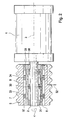
- Figure 1 shows a Anthebsan Aunt with cut illustrated drive element of an electric drive.
- the transmission element 5 configured according to the invention is, as shown in FIG. 1, connected to an output shaft 2 of a drive motor 1, such as e.g. an electric drive, recorded.
- the output shaft 2 of the electric drive 1 rotates in the direction of rotation 4 about the symmetry axis 3.
- the transmission element 5 is traversed by an axially extending bore 6, in which a spring set 8, sleeve-shaped driving elements 13 and 14 and support elements 11 and 12 added are.
- a support member 11 On the outer side of the bore 6 of the transmission element 5 passing through the output shaft 2, a support member 11 is movably received in the form of a sliding seat on the side facing the electrical drive 1 in the axial direction along a marked by reference numeral 19 Einstellweges. Furthermore, the output shaft 2 of the electric drive 1 is enclosed by a sleeve-shaped driving element 14. On the outside of the sleeve-shaped driving element 14 there are two identified by reference numerals 15 and 16 annular support portions which face the inside of the spring set 8. The spring set 8 in turn consists of a plurality of fins 40 as will be described in more detail below.
- a likewise displaceable support member 12 in the form of a sliding seat On the outside of the spring set 8 is at the free end of drive shaft 2 and spring set 8, a likewise displaceable support member 12 in the form of a sliding seat. Its maximum deflection according to the adjustment 19 for adjustment the radial rigidity of the combination of gear elements 5 and output shaft 2 of the electric drive 1, is given by a stop 21 which is spaced from the free end of the spring set 8 in a gap 22 provided with a gap.
- the spring set 8 is further surrounded by a ring-shaped driving element 13, whose annularly shaped support segments of the outer peripheral surface of the spring set 18 are facing.
- the driving element 13 is supported with its continuous flat side on the inside of the bore 6 of the transmission element 5, which in turn is provided at its outer periphery with a toothing 7.
- the toothing 7 may be a helical toothing; it can also be designed as a spur or a helical toothing.
- the worm wheel 18 rotates about an axis of rotation 20, which is arranged offset in relation to the output shaft 2 of the electric drive 1 by 90 °.
- the Einstellweg 19 is divided with respect to the line of symmetry 3 of the output shaft 2 of the electric drive 1 in a plurality of Einstellabposedn 19.1, 19.2, 19.3, 19.4 and 19.5, in which the support elements 11 and 12 and the driving elements 13 and 14 in one ring-shaped surrounding the spring set 8 cavity 9, ie the outer annular gap 9 in the axial direction or in an inner annular gap 10 are displaceable. If the support elements 11 and 12 configured as sliding seats are displaced into their positions corresponding to the setting distances 19.1 and 19.4, then a bending characteristic sets in which can be the optimum for a specific application.
- the adjusting itself by the arrangement of the sleeve-shaped driving elements 13 and 14 adjusting Drelmiomentenfluß is denoted by the dashed lines, which are identified by reference numeral 17 and the power flow from the output shaft 2 of the electric drive 1 via the inner sleeve-shaped Mitnaluneelement 14 configured in the spring set 8 and represent of this in the recorded in the outer gap 9 outer driving element 13.
- the torque is transmitted through the external teeth 7 of the transmission element 5 to the external teeth of the configured here as shown in FIG 1 as a worm further gear element 18, so that the torque Finally, the load torque on the worm wheel 18 can overcome.
- a spring set can be removed, which is provided on the outside and inside with sliding seats for adjusting the bending line of the combination gear element / output shaft of an electric drive.
- an electric drive 1 can be removed, whose output shaft 2 rotates about the symmetry line 3 in the direction of rotation 4.
- the spring set 8 is supported on the outer peripheral surface of the output shaft 2 by the support members 35 and 36 as shown in Figure 2, which in an analogous manner to the illustration of Figure 1 also as sliding in their respective gap 10 sliding seats are formed.
- two support elements 33 and 34 are also included, which are displaceable in the outer annular space 9 between the spring set 8 and the transmission element 5 in the axial direction.
- the entraining elements according to the illustration in FIG. 2 are identified by reference numerals 30 and 31 and are accommodated both in the outer annular gap 9 and in the inner annular gap 10.
- the torque applied by the electric drive 1 via the output shaft 2 via the intermediate spring set 2 is transmitted to the external teeth 7 of the transmission element 5.
- a bending line identified by reference numeral 37 is drawn, which is defined by the selected arrangement of the support elements 33 and 34 in the outer-gap ring 9 and by the position of the sliding seats 35 and 36, respectively, in the inner-annular gap 10.
- the force flow of the bending forces which is defined by the reference numeral 32 in Figure 2 adjusts an over the inner driven element 31 via the inner driving element 31 in the spring set 8 adjusting the course of the torque.
- the torque is introduced via the outer driving element 30, received in the outer annular gap 9 between the spring set 8 and the bore 6 of the transmission element 5 in this and via the teeth 7 in the manner analogous to Figure 1 manner to another transmission element - not shown - transferred.
- the progression identified by reference numeral 37 shows the resulting bending line resulting from the transmission of the bending forces via the sliding support elements 35 and 36 arranged in the inner annular gap 10 and the support elements 33 and 34 received in the outer annular gap 9 to the transmission element 5.
- FIG. 3.1 The illustration according to Figure 3.1 is the schematic diagram of a spring set with parallel slats removed.
- the representation according to FIG. 3.1 is a highly schematic representation of a spring set 8 in the form of a diagrammatic sketch.
- the spring set 8 comprises a parallel arrangement 2 arranged support elements in the form of sliding seats 33 and 34. Of the oriented in a parallel arrangement 41 slats 40 are between the spring set 8 and not shown output shaft 2 of the electric drive. 1 Received support elements, also as sliding seats 35, 36 procure, covered.
- the lamella 40 as shown in Figure 3.1 is a one-piece component, which receives a characteristic of a spring / damper element 45, 46 by the choice of slidably disposed support members 33, 34, 35 and 36, depending on the axial orientation of the support members 33 to 36.
- lamellae strands embedded in the circumferential segments of a spring set project parallel to each other and extend perpendicular to the plane of the drawing.
- the spring set 8 designed here as a cylinder configuration comprises individual elastomer segments 49, in which the individual lamella strands of the continuous lamella 40 extend according to the schematic diagram in FIG. 3.1 extending in the axial direction.
- the course of the fins, i. Parallel position to the line of symmetry 3 of the output shaft 2 of the electric drive 1 is perpendicular to or perpendicular to the plane in or out.
- the fins 40 are inserted without play in the elastomer segments 49 of the spring set 8.
- a spring set with slats in a vertical arrangement can be removed.
- the spring set 8 in a vertical position 42 oriented individual slats 40, which may be embodied for example in the form of a slotted beam.
- the fins 40 of the spring assembly 8 are arranged slightly inclined in the illustration of Figure 3.3 and designed as over the entire axial length of the output shaft 2 of the electric drive 1 extending flat springs.
- the spring set 8 can also be formed as an axially parallel to the symmetry axis 3 of the output shaft 2 of the electric drive 1 formed arrangement of wound profile elements 43.
- the profile elements 43 may be wound profile elements which extend overlapping each other in the axial direction along the adjustment path 19 of the output shaft 2 of the electric drive 1. Due to the voids extending between the individual profiled elements 43, this design variant of a spring set 8 has a high elasticity. Depending on the application, in which the inventively designed transmission element 5 is used, this may well be desired.
- an outer flat spring 44 Coaxial with the axis of symmetry 3 of the output shaft 2 of the electric drive 1, an outer flat spring 44 are shown, the fins 40 are arranged substantially in a vertical position relative to the symmetry axis 3 of the driven output shaft 2 - not shown here - the electric drive 1.
- the outer flat spring 44 extends continuously over the entire length of the output shaft 2 of the electric drive 1 and is shown interrupted for reasons of better representability in the middle.
- Below the outer flat spring 44 the fins 40 are oriented substantially in a vertical position 42, there is an internal spring element 44.1. As shown in FIG. 3.5, this spring element 44.1 can be arranged only in the initial region or in the end region of the continuously formed outer flat spring 44.
- the horizontal or the inner spring elements 44.1 are arranged concentrically with the outer flat spring element 44.
- the special applications better meet the spring set configurations as shown in Figure 3.3 and 3.4 ,
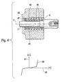
- the arrangement of Figure 4 is an output shaft 2 of an electric drive not shown here removed, which is symmetrical to the symmetry line 3.
- the output shaft 2 of the electric drive 1 not shown here is enclosed by a spring set 8, the individual slats 40 are received in a substantially vertical orientation 42.
- the spring set 8 according to the embodiment in Figure 4 an additional acting in the axial direction spring element 47 assigned.
- the additional axial spring element 47 is supported by a spring shoulder 53 in the gear element 5 surrounding it.
- the elasticity is almost completely integrated into a transmission element 5, the concept comprising a combination of fins 40, Mitnaluneijnn 13, 14 and 30 and 31 and support members 11 and 12 and 33, 34, 35 and 36.
- a network of elements spring and damper can be configured, the stiffness in the radial direction according to the reproduced in Figure 4 diagram depending on the radial deflection 42 a significant increase in the contact force 51 entails, as can be seen from the stiffness curve 50 the representation in Figure 4 can be read.
- the desired radial rigidity can thus be specified by appropriate displacement of the support members 11, 12, 33, 34, 35 and 36 in certain setting distances 19.1 to 19.5 along the axial Einstellweges 19, without causing the dimensions of the transmission element 5 change significantly.
Landscapes
- Engineering & Computer Science (AREA)
- General Engineering & Computer Science (AREA)
- Mechanical Engineering (AREA)
- Gears, Cams (AREA)
- Gear Transmission (AREA)
- Springs (AREA)
Claims (12)
- Élément d'engrenage (5, 18) comportant un élément d'engrenage (5) commandé côté entraînement par un moteur de commande (1), dont l'arbre entraîné (2) loge l'élément d'engrenage (5) muni d'une denture extérieure (7) à sa surface périphérique qui engrène d'autres éléments d'engrenage (18) ayant une ou plusieurs dentures,
caractérisé en ce que
des éléments d'appui réglables axialement (11, 12 ; 33, 34, 35, 36) et des éléments d'entraînement en forme de manchon (13, 14 ; 30, 31) sont logés entre l'arbre entraîné (2) et un jeu de ressorts (8) et entre le jeu de ressorts (8) et l'élément d'engrenage (5). - Élément d'engrenage (5, 18) comportant un élément d'engrenage (5) selon la revendication 1,
caractérisé en ce que
les éléments d'appui mobiles axialement (11, 12 ; 33, 34, 35, 36) et les éléments d'entraînement en forme de manchon (13, 14 ; 30, 31) sont logés dans des cavités en forme de fente annulaire (9, 10). - Élément d'engrenage (5, 18) comportant un élément d'engrenage (5) selon la revendication 1,
caractérisé en ce qu'
une surface de butée (21) formée sur l'élément d'engrenage (5) limite le déplacement axial maximum des éléments d'appui (11, 12 ; 33, 34, 35, 36). - Élément d'engrenage (5, 18) comportant un élément d'engrenage (5) selon la revendication 1,
caractérisé en ce que
la longueur axiale de l'élément d'engrenage (5) est subdivisée en intervalles de réglage séparés (19.1 à 19.5) subdivisant le chemin de réglage (19). - Élément d'engrenage (5, 18) comportant un élément d'engrenage (5) selon la revendication 1,
caractérisé en ce que
les éléments d'entraînement (13, 14) comprennent des patins de suspension circulaires (15, 16) placés contre le jeu de ressorts (8) sur la face interne et/ou la face externe de celui-ci. - Élément d'engrenage (5, 18) comportant un élément d'engrenage (5) selon la revendication 1,
caractérisé en ce que
le jeu de ressorts (8) comprend des lamelles (40) relativement mobiles les unes par rapport aux autres, les lamelles (40) agissant comme un élément de ressort/d'amortissement (45, 46). - Élément d'engrenage (5, 18) comportant un élément d'engrenage (5) selon la revendication 6,
caractérisé en ce que
les lamelles (40) sont orientées vers l'arbre entraîné (2) sensiblement en couches parallèles (41). - Élément d'engrenage (5, 18) comportant un élément d'engrenage (5) selon la revendication 6,
caractérisé en ce que
les lamelles (40) sont orientées vers l'arbre entraîné (2) sensiblement en couches verticales (41). - Élément d'engrenage (5, 18) comportant un élément d'engrenage (5) selon la revendication 7,
caractérisé en ce que
les lamelles (40) sont encastrées dans des segments d'élastomère (49) d'un jeu de ressorts cylindrique (8). - Élément d'engrenage (5, 18) comportant un élément d'engrenage (5) selon la revendication 6,
caractérisé en ce que
les lamelles (40) sont des éléments profilés enroulés (43) dans le jeu de ressorts (8). - Élément d'engrenage (5, 18) comportant un élément d'engrenage (5) selon la revendication 6,
caractérisé en ce que
les lamelles (40) des ressorts (8) plats concentriques (44, 44.1) montés dans le jeu de ressorts (8). - Élément d'engrenage (5, 18) comportant un élément d'engrenage (5) selon la revendication 6,
caractérisé en ce qu'
un ressort axial supplémentaire (47) est associé aux lamelles (40) du jeu de ressorts (8).
Applications Claiming Priority (5)
| Application Number | Priority Date | Filing Date | Title |
|---|---|---|---|
| DE10057117 | 2000-11-16 | ||
| DE10057117 | 2000-11-16 | ||
| DE10124601 | 2001-05-21 | ||
| DE10124601A DE10124601A1 (de) | 2000-11-16 | 2001-05-21 | Getriebeelement zur spielfreien Drehmomentübertragung |
| PCT/DE2001/004145 WO2002040897A1 (fr) | 2000-11-16 | 2001-11-03 | Element d'engrenage destine a la transmission d'un couple sans jeu |
Publications (2)
| Publication Number | Publication Date |
|---|---|
| EP1337771A1 EP1337771A1 (fr) | 2003-08-27 |
| EP1337771B1 true EP1337771B1 (fr) | 2007-02-28 |
Family
ID=26007696
Family Applications (1)
| Application Number | Title | Priority Date | Filing Date |
|---|---|---|---|
| EP01996703A Expired - Lifetime EP1337771B1 (fr) | 2000-11-16 | 2001-11-03 | Element d'engrenage destine a la transmission d'un couple sans jeu |
Country Status (7)
| Country | Link |
|---|---|
| US (1) | US7665379B2 (fr) |
| EP (1) | EP1337771B1 (fr) |
| JP (1) | JP4272883B2 (fr) |
| CN (1) | CN1234978C (fr) |
| DE (1) | DE50112139D1 (fr) |
| ES (1) | ES2280431T3 (fr) |
| WO (1) | WO2002040897A1 (fr) |
Families Citing this family (9)
| Publication number | Priority date | Publication date | Assignee | Title |
|---|---|---|---|---|
| JP2007054969A (ja) * | 2005-08-22 | 2007-03-08 | Funai Electric Co Ltd | 画像形成装置 |
| CN100425881C (zh) * | 2006-12-08 | 2008-10-15 | 宁新华 | 精密蜗轮蜗杆传动消隙装置 |
| CN102235478A (zh) * | 2010-04-28 | 2011-11-09 | 鸿富锦精密工业(深圳)有限公司 | 齿轮及采用该齿轮的传动机构 |
| EP2620665A1 (fr) * | 2012-01-25 | 2013-07-31 | Siemens Aktiengesellschaft | Embrayage à couple et procédé de réglage d'un embrayage à couple |
| DE102013207142B4 (de) * | 2013-04-19 | 2014-12-11 | Ford Global Technologies, Llc | Schneckengetriebe |
| DE102015201938A1 (de) * | 2015-02-04 | 2016-08-04 | Thyssenkrupp Ag | Vorrichtung zur Einbringung eines Hilfsdrehmoments in eine Lenkwelle |
| CN107647987B (zh) * | 2017-09-30 | 2023-11-24 | 美而特智能后勤服务有限公司 | 一种用于轮椅的蜗杆传动机构 |
| CN107496089B (zh) * | 2017-09-30 | 2023-12-01 | 安徽未易智能科技有限公司 | 一种用于轮椅的可调控蜗杆传动机构 |
| CN110194210B (zh) * | 2019-05-30 | 2021-08-31 | 奇瑞汽车股份有限公司 | 一种转向器的齿轮轴间隙调整结构 |
Family Cites Families (10)
| Publication number | Priority date | Publication date | Assignee | Title |
|---|---|---|---|---|
| FR712311A (fr) | 1930-06-11 | 1931-09-30 | Cie Radio Cinema | Dispositif d'entraînement par engrenages et vis sans fin à irrégularités corrigées |
| US3147640A (en) * | 1960-04-13 | 1964-09-08 | United Shoe Machinery Corp | Wave generator for wave converter |
| US3635100A (en) * | 1970-04-15 | 1972-01-18 | Dura Corp | Motor drive assembly for window regulators |
| US3851538A (en) * | 1973-05-21 | 1974-12-03 | Philadelphia Gear Corp | Torque switch mechanism |
| JPS57103131A (en) | 1980-12-18 | 1982-06-26 | Sony Corp | Biaxial driver |
| JPH0439456A (ja) | 1990-05-31 | 1992-02-10 | Ishizaki Honten:Kk | ウォーム減速機 |
| US5513543A (en) * | 1993-03-26 | 1996-05-07 | Mpc Products | Adjustable control lever with variable pressure detent |
| JP3305523B2 (ja) | 1994-11-25 | 2002-07-22 | 九州電力株式会社 | 電線接続用絶縁被覆付スリーブ |
| DE19713423C5 (de) * | 1996-04-03 | 2015-11-26 | Schaeffler Technologies AG & Co. KG | Vorrichtung und Verfahren zur Betätigung eines Getriebes |
| US6520042B2 (en) * | 1999-10-07 | 2003-02-18 | Delphi Technologies, Inc. | Electric power steering assist mechanism |
-
2001
- 2001-11-03 EP EP01996703A patent/EP1337771B1/fr not_active Expired - Lifetime
- 2001-11-03 WO PCT/DE2001/004145 patent/WO2002040897A1/fr not_active Ceased
- 2001-11-03 ES ES01996703T patent/ES2280431T3/es not_active Expired - Lifetime
- 2001-11-03 US US10/415,895 patent/US7665379B2/en not_active Expired - Fee Related
- 2001-11-03 CN CN01819011.1A patent/CN1234978C/zh not_active Expired - Fee Related
- 2001-11-03 DE DE50112139T patent/DE50112139D1/de not_active Expired - Lifetime
- 2001-11-03 JP JP2002543184A patent/JP4272883B2/ja not_active Expired - Fee Related
Also Published As
| Publication number | Publication date |
|---|---|
| EP1337771A1 (fr) | 2003-08-27 |
| JP2004514102A (ja) | 2004-05-13 |
| ES2280431T3 (es) | 2007-09-16 |
| WO2002040897A1 (fr) | 2002-05-23 |
| DE50112139D1 (de) | 2007-04-12 |
| CN1474916A (zh) | 2004-02-11 |
| CN1234978C (zh) | 2006-01-04 |
| US7665379B2 (en) | 2010-02-23 |
| US20040035230A1 (en) | 2004-02-26 |
| JP4272883B2 (ja) | 2009-06-03 |
Similar Documents
| Publication | Publication Date | Title |
|---|---|---|
| DE69913345T2 (de) | Elektrische servolenkung | |
| EP2836416B1 (fr) | Palier libre pour mécanisme de direction | |
| EP2132458B1 (fr) | Transmission coaxiale, en particulier transmission a arbre creux, destinee à l'entrainement industriel | |
| EP1552097B1 (fr) | Dispositif d'engrenage, en particulier pour des mecanismes de reglage de vehicules automobiles | |
| EP2786040B1 (fr) | Système d'arbre et procédé de transmission de couples de rotation agissant autour d'un axe de rotation | |
| EP1101044B1 (fr) | Silentbloc a course radiale limitee et conduit de fluide amortisseur | |
| EP3717801B1 (fr) | Mécanisme d'entraînement à vis sans fin | |
| DE102009000014B4 (de) | Kupplungsvorrichtung | |
| EP1337771A1 (fr) | Element d'engrenage destine a la transmission d'un couple sans jeu | |
| EP3985283A1 (fr) | Pas d'engrenage sans jeu | |
| DE10161356A1 (de) | Schraubgerät | |
| EP2530260B1 (fr) | Arbre d'embrayage, actionneur, boîte de vitesses à dispositif de réglage d'arbre à came et régulateur de l'arbre à came | |
| DE19951988B4 (de) | Planetenreibradgetriebe mit Anpressmitteln | |
| EP1931896A1 (fr) | Unite de transmission et d'entrainement a compensation du jeu axial | |
| EP1440250B1 (fr) | Palier en caoutchouc provoquant un amortissement hydraulique | |
| EP4095015B1 (fr) | Agencement de piéce de pression pour une direction de véhicule automobile | |
| WO2017125554A1 (fr) | Actionneur équipé d'une vis creuse | |
| DE10124601A1 (de) | Getriebeelement zur spielfreien Drehmomentübertragung | |
| DE20115350U1 (de) | Drehverbindung | |
| EP2191154B1 (fr) | Palier à roulement pour des pièces pouvant être décalées axialement les unes par rapport aux autres, en particulier pour des éléments de changement de vitesse | |
| DE102017112924A1 (de) | Planetengetriebe | |
| DE102004043136B3 (de) | Drehfeder, Drehfederersatz und Anordnung von Drehfedersätzen | |
| DE10392948B4 (de) | Drehbarer Antrieb und Schaltmechanismus mit diesem drehbaren Antrieb | |
| EP2935957A1 (fr) | Soupape de régulation de débit réglable en fonction de la viscosité | |
| DE102024204056B3 (de) | Tripodestern für ein Tripodegelenk |
Legal Events
| Date | Code | Title | Description |
|---|---|---|---|
| PUAI | Public reference made under article 153(3) epc to a published international application that has entered the european phase |
Free format text: ORIGINAL CODE: 0009012 |
|
| 17P | Request for examination filed |
Effective date: 20030616 |
|
| AK | Designated contracting states |
Designated state(s): AT BE CH CY DE DK ES FI FR GB GR IE IT LI LU MC NL PT SE TR |
|
| RBV | Designated contracting states (corrected) |
Designated state(s): DE ES FR IT |
|
| GRAP | Despatch of communication of intention to grant a patent |
Free format text: ORIGINAL CODE: EPIDOSNIGR1 |
|
| GRAS | Grant fee paid |
Free format text: ORIGINAL CODE: EPIDOSNIGR3 |
|
| GRAA | (expected) grant |
Free format text: ORIGINAL CODE: 0009210 |
|
| AK | Designated contracting states |
Kind code of ref document: B1 Designated state(s): DE ES FR IT |
|
| REF | Corresponds to: |
Ref document number: 50112139 Country of ref document: DE Date of ref document: 20070412 Kind code of ref document: P |
|
| ET | Fr: translation filed | ||
| REG | Reference to a national code |
Ref country code: ES Ref legal event code: FG2A Ref document number: 2280431 Country of ref document: ES Kind code of ref document: T3 |
|
| PLBE | No opposition filed within time limit |
Free format text: ORIGINAL CODE: 0009261 |
|
| STAA | Information on the status of an ep patent application or granted ep patent |
Free format text: STATUS: NO OPPOSITION FILED WITHIN TIME LIMIT |
|
| 26N | No opposition filed |
Effective date: 20071129 |
|
| PGFP | Annual fee paid to national office [announced via postgrant information from national office to epo] |
Ref country code: ES Payment date: 20141120 Year of fee payment: 14 |
|
| PGFP | Annual fee paid to national office [announced via postgrant information from national office to epo] |
Ref country code: FR Payment date: 20141118 Year of fee payment: 14 |
|
| PGFP | Annual fee paid to national office [announced via postgrant information from national office to epo] |
Ref country code: IT Payment date: 20141125 Year of fee payment: 14 |
|
| PGFP | Annual fee paid to national office [announced via postgrant information from national office to epo] |
Ref country code: DE Payment date: 20150127 Year of fee payment: 14 |
|
| REG | Reference to a national code |
Ref country code: DE Ref legal event code: R119 Ref document number: 50112139 Country of ref document: DE |
|
| PG25 | Lapsed in a contracting state [announced via postgrant information from national office to epo] |
Ref country code: IT Free format text: LAPSE BECAUSE OF NON-PAYMENT OF DUE FEES Effective date: 20151103 |
|
| REG | Reference to a national code |
Ref country code: FR Ref legal event code: ST Effective date: 20160729 |
|
| PG25 | Lapsed in a contracting state [announced via postgrant information from national office to epo] |
Ref country code: DE Free format text: LAPSE BECAUSE OF NON-PAYMENT OF DUE FEES Effective date: 20160601 |
|
| PG25 | Lapsed in a contracting state [announced via postgrant information from national office to epo] |
Ref country code: FR Free format text: LAPSE BECAUSE OF NON-PAYMENT OF DUE FEES Effective date: 20151130 |
|
| PG25 | Lapsed in a contracting state [announced via postgrant information from national office to epo] |
Ref country code: ES Free format text: LAPSE BECAUSE OF NON-PAYMENT OF DUE FEES Effective date: 20151104 |
|
| REG | Reference to a national code |
Ref country code: ES Ref legal event code: FD2A Effective date: 20180626 |