EP1338477A2 - Dispositif et procédé de détection d'obstacles pour véhicules - Google Patents
Dispositif et procédé de détection d'obstacles pour véhicules Download PDFInfo
- Publication number
- EP1338477A2 EP1338477A2 EP03003851A EP03003851A EP1338477A2 EP 1338477 A2 EP1338477 A2 EP 1338477A2 EP 03003851 A EP03003851 A EP 03003851A EP 03003851 A EP03003851 A EP 03003851A EP 1338477 A2 EP1338477 A2 EP 1338477A2
- Authority
- EP
- European Patent Office
- Prior art keywords
- vehicle
- distance
- displacement amount
- obstacle
- determined
- Prior art date
- Legal status (The legal status is an assumption and is not a legal conclusion. Google has not performed a legal analysis and makes no representation as to the accuracy of the status listed.)
- Granted
Links
- 238000001514 detection method Methods 0.000 title claims abstract description 49
- 238000000034 method Methods 0.000 title claims description 24
- 238000012545 processing Methods 0.000 claims abstract description 40
- 238000006073 displacement reaction Methods 0.000 claims description 45
- 230000001133 acceleration Effects 0.000 claims description 12
- 238000003384 imaging method Methods 0.000 claims description 2
- 238000004364 calculation method Methods 0.000 description 14
- 238000003672 processing method Methods 0.000 description 6
- 238000010586 diagram Methods 0.000 description 4
- 238000012886 linear function Methods 0.000 description 4
- 239000002184 metal Substances 0.000 description 4
- 230000008901 benefit Effects 0.000 description 3
- 238000005259 measurement Methods 0.000 description 3
- 238000012986 modification Methods 0.000 description 3
- 230000004048 modification Effects 0.000 description 3
- 238000010276 construction Methods 0.000 description 2
- 229910000831 Steel Inorganic materials 0.000 description 1
- 238000013459 approach Methods 0.000 description 1
- 230000000694 effects Effects 0.000 description 1
- 238000012544 monitoring process Methods 0.000 description 1
- 230000002093 peripheral effect Effects 0.000 description 1
- 229920000747 poly(lactic acid) Polymers 0.000 description 1
- 238000004549 pulsed laser deposition Methods 0.000 description 1
- 239000010959 steel Substances 0.000 description 1
Images



Classifications
-
- G—PHYSICS
- G08—SIGNALLING
- G08G—TRAFFIC CONTROL SYSTEMS
- G08G1/00—Traffic control systems for road vehicles
- G08G1/16—Anti-collision systems
-
- G—PHYSICS
- G01—MEASURING; TESTING
- G01S—RADIO DIRECTION-FINDING; RADIO NAVIGATION; DETERMINING DISTANCE OR VELOCITY BY USE OF RADIO WAVES; LOCATING OR PRESENCE-DETECTING BY USE OF THE REFLECTION OR RERADIATION OF RADIO WAVES; ANALOGOUS ARRANGEMENTS USING OTHER WAVES
- G01S13/00—Systems using the reflection or reradiation of radio waves, e.g. radar systems; Analogous systems using reflection or reradiation of waves whose nature or wavelength is irrelevant or unspecified
- G01S13/02—Systems using reflection of radio waves, e.g. primary radar systems; Analogous systems
- G01S13/06—Systems determining position data of a target
- G01S13/08—Systems for measuring distance only
- G01S13/32—Systems for measuring distance only using transmission of continuous waves, whether amplitude-, frequency-, or phase-modulated, or unmodulated
- G01S13/34—Systems for measuring distance only using transmission of continuous waves, whether amplitude-, frequency-, or phase-modulated, or unmodulated using transmission of continuous, frequency-modulated waves while heterodyning the received signal, or a signal derived therefrom, with a locally-generated signal related to the contemporaneously transmitted signal
- G01S13/348—Systems for measuring distance only using transmission of continuous waves, whether amplitude-, frequency-, or phase-modulated, or unmodulated using transmission of continuous, frequency-modulated waves while heterodyning the received signal, or a signal derived therefrom, with a locally-generated signal related to the contemporaneously transmitted signal using square or rectangular modulation, e.g. diplex radar for ranging over short distances
-
- G—PHYSICS
- G01—MEASURING; TESTING
- G01S—RADIO DIRECTION-FINDING; RADIO NAVIGATION; DETERMINING DISTANCE OR VELOCITY BY USE OF RADIO WAVES; LOCATING OR PRESENCE-DETECTING BY USE OF THE REFLECTION OR RERADIATION OF RADIO WAVES; ANALOGOUS ARRANGEMENTS USING OTHER WAVES
- G01S11/00—Systems for determining distance or velocity not using reflection or reradiation
- G01S11/12—Systems for determining distance or velocity not using reflection or reradiation using electromagnetic waves other than radio waves
-
- G—PHYSICS
- G01—MEASURING; TESTING
- G01S—RADIO DIRECTION-FINDING; RADIO NAVIGATION; DETERMINING DISTANCE OR VELOCITY BY USE OF RADIO WAVES; LOCATING OR PRESENCE-DETECTING BY USE OF THE REFLECTION OR RERADIATION OF RADIO WAVES; ANALOGOUS ARRANGEMENTS USING OTHER WAVES
- G01S13/00—Systems using the reflection or reradiation of radio waves, e.g. radar systems; Analogous systems using reflection or reradiation of waves whose nature or wavelength is irrelevant or unspecified
- G01S13/86—Combinations of radar systems with non-radar systems, e.g. sonar, direction finder
- G01S13/867—Combination of radar systems with cameras
-
- G—PHYSICS
- G01—MEASURING; TESTING
- G01S—RADIO DIRECTION-FINDING; RADIO NAVIGATION; DETERMINING DISTANCE OR VELOCITY BY USE OF RADIO WAVES; LOCATING OR PRESENCE-DETECTING BY USE OF THE REFLECTION OR RERADIATION OF RADIO WAVES; ANALOGOUS ARRANGEMENTS USING OTHER WAVES
- G01S13/00—Systems using the reflection or reradiation of radio waves, e.g. radar systems; Analogous systems using reflection or reradiation of waves whose nature or wavelength is irrelevant or unspecified
- G01S13/88—Radar or analogous systems specially adapted for specific applications
- G01S13/93—Radar or analogous systems specially adapted for specific applications for anti-collision purposes
- G01S13/931—Radar or analogous systems specially adapted for specific applications for anti-collision purposes of land vehicles
-
- B—PERFORMING OPERATIONS; TRANSPORTING
- B60—VEHICLES IN GENERAL
- B60R—VEHICLES, VEHICLE FITTINGS, OR VEHICLE PARTS, NOT OTHERWISE PROVIDED FOR
- B60R21/00—Arrangements or fittings on vehicles for protecting or preventing injuries to occupants or pedestrians in case of accidents or other traffic risks
- B60R21/01—Electrical circuits for triggering passive safety arrangements, e.g. airbags, safety belt tighteners, in case of vehicle accidents or impending vehicle accidents
- B60R21/013—Electrical circuits for triggering passive safety arrangements, e.g. airbags, safety belt tighteners, in case of vehicle accidents or impending vehicle accidents including means for detecting collisions, impending collisions or roll-over
- B60R21/0134—Electrical circuits for triggering passive safety arrangements, e.g. airbags, safety belt tighteners, in case of vehicle accidents or impending vehicle accidents including means for detecting collisions, impending collisions or roll-over responsive to imminent contact with an obstacle, e.g. using radar systems
-
- G—PHYSICS
- G01—MEASURING; TESTING
- G01S—RADIO DIRECTION-FINDING; RADIO NAVIGATION; DETERMINING DISTANCE OR VELOCITY BY USE OF RADIO WAVES; LOCATING OR PRESENCE-DETECTING BY USE OF THE REFLECTION OR RERADIATION OF RADIO WAVES; ANALOGOUS ARRANGEMENTS USING OTHER WAVES
- G01S13/00—Systems using the reflection or reradiation of radio waves, e.g. radar systems; Analogous systems using reflection or reradiation of waves whose nature or wavelength is irrelevant or unspecified
- G01S13/86—Combinations of radar systems with non-radar systems, e.g. sonar, direction finder
-
- G—PHYSICS
- G01—MEASURING; TESTING
- G01S—RADIO DIRECTION-FINDING; RADIO NAVIGATION; DETERMINING DISTANCE OR VELOCITY BY USE OF RADIO WAVES; LOCATING OR PRESENCE-DETECTING BY USE OF THE REFLECTION OR RERADIATION OF RADIO WAVES; ANALOGOUS ARRANGEMENTS USING OTHER WAVES
- G01S13/00—Systems using the reflection or reradiation of radio waves, e.g. radar systems; Analogous systems using reflection or reradiation of waves whose nature or wavelength is irrelevant or unspecified
- G01S13/88—Radar or analogous systems specially adapted for specific applications
- G01S13/93—Radar or analogous systems specially adapted for specific applications for anti-collision purposes
- G01S13/931—Radar or analogous systems specially adapted for specific applications for anti-collision purposes of land vehicles
- G01S2013/932—Radar or analogous systems specially adapted for specific applications for anti-collision purposes of land vehicles using own vehicle data, e.g. ground speed, steering wheel direction
-
- G—PHYSICS
- G01—MEASURING; TESTING
- G01S—RADIO DIRECTION-FINDING; RADIO NAVIGATION; DETERMINING DISTANCE OR VELOCITY BY USE OF RADIO WAVES; LOCATING OR PRESENCE-DETECTING BY USE OF THE REFLECTION OR RERADIATION OF RADIO WAVES; ANALOGOUS ARRANGEMENTS USING OTHER WAVES
- G01S13/00—Systems using the reflection or reradiation of radio waves, e.g. radar systems; Analogous systems using reflection or reradiation of waves whose nature or wavelength is irrelevant or unspecified
- G01S13/88—Radar or analogous systems specially adapted for specific applications
- G01S13/93—Radar or analogous systems specially adapted for specific applications for anti-collision purposes
- G01S13/931—Radar or analogous systems specially adapted for specific applications for anti-collision purposes of land vehicles
- G01S2013/9323—Alternative operation using light waves
-
- G—PHYSICS
- G01—MEASURING; TESTING
- G01S—RADIO DIRECTION-FINDING; RADIO NAVIGATION; DETERMINING DISTANCE OR VELOCITY BY USE OF RADIO WAVES; LOCATING OR PRESENCE-DETECTING BY USE OF THE REFLECTION OR RERADIATION OF RADIO WAVES; ANALOGOUS ARRANGEMENTS USING OTHER WAVES
- G01S13/00—Systems using the reflection or reradiation of radio waves, e.g. radar systems; Analogous systems using reflection or reradiation of waves whose nature or wavelength is irrelevant or unspecified
- G01S13/88—Radar or analogous systems specially adapted for specific applications
- G01S13/93—Radar or analogous systems specially adapted for specific applications for anti-collision purposes
- G01S13/931—Radar or analogous systems specially adapted for specific applications for anti-collision purposes of land vehicles
- G01S2013/9327—Sensor installation details
- G01S2013/93271—Sensor installation details in the front of the vehicles
Definitions
- the invention generally relates to an obstacle detection device for a vehicle, which is mounted in the vehicle, to help a driver become aware of obstacles and the like. More specifically, the invention relates to an obstacle detection device for a vehicle which minimizes the false recognition of objects that cause virtual images in a captured image.
- CCD cameras have the benefit of being able to detect lane markings and lights and the like on the road, but are inferior in terms of accuracy with far distances because they calculate distance using a captured image.
- millimeter wave radar has the benefit of being extremely accurate with distances, but can only detect objects that have a large reflection coefficient.
- an obstacle detection device for a vehicle such as that disclosed in Japanese Patent Laid-Open Publication No. 8-156723, for example, has been proposed.
- This obstacle detection device for a vehicle compares the distance to an object in front of the vehicle calculated from an image captured by a CCD camera with the distance to the object ranged by the millimeter wave radar, and then recognizes the object as an obstacle when the distances match.
- This obstacle detection device for a vehicle makes use of the strong points of the CCD camera and the millimeter wave radar to make up for their weak points, thus enabling reliable recognition of an obstacle.
- This type of obstacle detection device for a vehicle compares the calculation results from the captured image with the measurement results from the millimeter wave radar at a predetermined interval of time (e.g., every 1s). When the results match such that a highly dangerous situation is detected, a warning is issued and the user is alerted. To prevent a collision, the user is alerted the instant that both the results match up and the obstacle enters an area where the danger of collision is high.
- a virtual image created by the reflection of the road surface may be captured on the image that is captured by the CCD camera. This virtual image is not a real object, and therefore will not be detected by the millimeter wave radar.
- This type of erroneous warning may cause the user to distrust the obstacle detection device for a vehicle, thereby hurting the merchantability of the obstacle detection device for a vehicle.
- the invention thus provides an obstacle detection device for a vehicle capable of reliably discriminating between a virtual object of the kind described above and a real object, in which accuracy and reliability has been improved.
- an obstacle detection device for a vehicle is provided with a first measuring means and a second measuring means having a respectively different characteristic, and which determines a distance between the vehicle and an object in the vicinity of the vehicle, and a controller that determines the object to be an obstacle if at least one of a displacement amount of the distance, displacement amount of a relative velocity or displacement amount of a relative acceleration between the object and the vehicle at a predetermined interval that was determined by the first measuring means is consistent (i.e. substantially equal) with a distance between the obstacle and the vehicle that was determined by the second measuring means with the same timing as the measurement by the first measuring means.
- an obstacle detection method of the obstacle detection device for a vehicle includes determining by a first measuring means a distance between the vehicle and an object, determining by a second measuring means that has a different characteristic than the first measuring means the distance between the vehicle and the object, and determining the object to be an obstacle when the values determined in the first measuring step are consistent with the values obtained from the second measuring step.
- FIG. 1 is a block diagram of an obstacle detection device 10 for a vehicle according to one exemplary embodiment of the invention.
- This obstacle detection device 10 for a vehicle is provided with a CCD (stereo) camera (image capturing portion) 12 as imaging means, an image processing unit 16 connected to the CCD camera 12, a radar ranging portion 14 as radar ranging means, and an electronic control unit (ECU) 18 connected to the image processing unit 16 and the radar ranging portion 14.
- a warning device 20 that issues a warning is also connected to this obstacle detection device 10 for a vehicle.
- the CCD camera 12 is mounted so as to capture an image of an area in front of the vehicle, e.g., the CCD camera 12 is fixed near the rearview mirror inside the vehicle cabin.
- the image data of the image (hereinafter, this image will be referred to as "captured image") captured by the CCD camera 12 is sent to the image processing unit 16 at a predetermined interval of time.
- the radar ranging portion 14 is mounted so as to range an object in front of the vehicle, e.g., the radar ranging portion 14 is mounted near the front grille of the vehicle.
- This radar ranging portion 14 is preferably a millimeter wave radar, which is relatively unaffected by weather conditions such as rain and fog, but may also be a laser radar.
- the radar ranging portion 14 emits radar waves toward a predetermined area in front of the vehicle and receives the waves reflected off of objects in that predetermined area, thereby obtaining radar information such as the velocity Vr, the distance Lr, and the direction ⁇ r of the object.
- the radar ranging portion 14 may calculate the velocity Vr using a radar wave Doppler frequency, or it may calculate the distance Lr from the phase information of the two frequencies. Also, the radar ranging portion 14 may one-dimensionally or two-dimensionally scan the emitted beam and detect the direction ⁇ r of the object. This radar information is then sent to the electronic control unit 18.
- CW Continuous Wave
- the image processing unit 16 processes the image data from the CCD camera 12 and obtains the image information relating to the distance L, the direction ⁇ , and the velocity V of the object in the captured image. This image information is sent to the electronic control unit 18.
- the image processing unit 16 may also recognize lane markings on the road and output only image information relating to the object in a specified area.
- the electronic control unit 18 determines the consistency of the radar information from the radar ranging portion 14 with the image information from the image processing unit 16 and determines an object relating to the consistent radar and image information to be an obstacle (an object with which the vehicle is in danger of colliding shall be referred to as "obstacle” in this specification) with which the vehicle is in danger of colliding.
- the image processing method of the image processing unit 16 applied to this invention presupposes the calculation of distance from image data which does not include distance information.
- FIG. 2 is a diagram illustrating an exemplary embodiment of the image processing method of the image processing unit 16.
- FIG. 2A is a top view schematically showing the view when capturing the image.
- FIG. 2B is a view schematically showing the captured image corresponding to that view.
- FIG. 2B shows a virtual image VI of an object A on the captured image. This virtual image VI is created in the captured image by a reflection point B (e.g. a puddle) on the road shown in FIG. 2A.
- a reflection point B e.g. a puddle
- FIG. 2A a localized puddle is shown to make it easier to visualize in the figure.
- FIG. 2B the captured image when the puddle extends all the way to the object A is shown.
- the distance calculation method by the image processing unit 16 calculates the distance from the difference on a two-dimensional coordinate system on the captured image containing a vanishing point P on the horizon.
- the distance calculation method also calculates the distance with respect to the object A using the closest point from a reference line L of a real image RI of the object A. That is, a distance C1 on the captured image is used in the distance calculation for the real image RI of the object A of the FIG. 2B.
- a distance C2 on the captured image can also be used in the distance calculation for the virtual image V1 of the object A in FIG. 2B.
- Vc2 ⁇ C2/ ⁇ T.
- the direction calculation method by the image processing unit 16 calculates using two-dimensional coordinates on the captured image. That is, this direction calculation method calculates both the vector from the location of the vehicle to the real image RI of the object A and the vector from the location of the vehicle to the virtual image VI of the object A, and then derives the direction ⁇ 1 of the real image RI and the direction ⁇ 2 of the virtual image VI with respect to the vehicle.
- the thus obtained distance L1, the velocity V1, and the direction ⁇ 1 relating to the real image RI are consistent with the respective distance Lr1, the velocity Vr1, and the direction ⁇ r1 relating to the object A of the radar information.
- the term “consistent” in this specification is used in view of the fact that the value of the radar information and the value of the captured image will not match due to differences of calculation accuracy and the like. Therefore, the term “consistent” shall be considered to also include cases in which both values correspond in some manner, i.e., both values will be substantially equal in some matter.
- the radar ranging portion 14 fundamentally does not range the reflection point B such as a puddle. Accordingly, information consistent with the distance L2, the velocity V2, and the direction ⁇ 2 relating to the virtual image VI does not exist in the radar information of the radar ranging portion 14. As a result, the electronic control unit 18 does not determine the virtual image VI (reflection point B) to be an obstacle so a problem does not normally occur.
- the radar ranging portion 14 outputs radar information regarding objects that will not become obstacles (hereinafter, this type of object shall be referred to as "non-obstacle C"), such as metal objects such as cans and steel sheet joints where roads and bridges meet and the like. Accordingly, when the obstacle detection device 10 for a vehicle is constructed to confirm the consistency of only information relating to the distance and direction between the radar information and the image information, as with the related art, that obstacle detection device 10 for a vehicle would erroneously recognize the non-object C as an obstacle when the non-object C is in the same location as the reflection point B.
- this kind of erroneous recognition is able to be minimized because the obstacle detection device 10 confirms the consistency, between the radar information and the image information, of the information relating to velocity as well as the consistency of the information relating to the distance and direction. This is based on the fact that the velocity V2 relating to the virtual image V (i.e., the reflection point B) in the image information is not consistent with a velocity Vr3 relating to the non-obstacle C in the radar information.
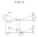
- the height HC of the CCD camera 12 and the height HA of the obstacle A shall be made the same.
- ⁇ L1 and ⁇ L3 in the lower graph of FIG. 3 denote the amounts of movement (the direction approaching the vehicle shall be positive) of the object A and the non-object C, respectively, with respect to the vehicle after the interval of time ⁇ T has passed. Accordingly, supposing that the non-object C is a stationary object, ⁇ L3 would show the absolute amount of movement of the vehicle at the interval of time ⁇ T.
- This ⁇ L2 is normally very different from ⁇ L3.
- ⁇ T 0.1s
- the difference between the amount of movement ⁇ L2 and the amount of movement ⁇ L3 is sufficiently large, the difference between the amount of movement Vc2 of the reflection point B (or more accurately, of the virtual image VI relating to the object A) per unit of time in the captured image and the amount of movement Vc3 of the non-obstacle C (or more accurately, the real image RI relating to the non-obstacle C) per unit of time becomes sufficiently evident even considering the relatively low accuracy of the image processing unit 16.
- This velocity V3 is consistent with the velocity Vr3 relating to the non-obstacle C of the radar information, so it is understandable that the velocity V2, which is largely different from the velocity V3, is largely different from the velocity Vr3 (i.e., the velocity V2 will not be consistent with the velocity Vr3).
- FIG. 4 is a flowchart showing a process of the electronic control unit 18.
- the electronic control unit 18 receives radar information and image information at a predetermined interval of time ⁇ T. This process starts when the ignition switch is turned ON.
- step 102 the electronic control unit 18 determines whether the velocity of the radar information and the velocity of the image information are consistent. When consistency is able to be confirmed, the process proceeds on to step 104.
- the electronic control unit 18 determines the object A relating to the radar information and image information that are consistent to be an obstacle. At this time, it is preferable that the electronic control unit 18 further determine whether a warning should be issued considering the velocity of the vehicle, along with the location and velocity of the obstacle. Alternatively, the electronic control unit 18 may also send the determination results to a warning determination circuit that determines whether a warning should be issued. In this case, the warning determination circuit determines whether a warning should be issued considering the velocity of the vehicle, along with the location and velocity of the obstacle. The velocity of the vehicle may be input to the electronic control unit 18 from a vehicle speed sensor (not shown) that is connected to the electronic control unit 18. When the electronic control unit 18 has ultimately determined that a warning should be issued, it sends a signal to the warning device 20 instructing the warning device 20 to issue a warning.
- the obstacle detection device 10 for a vehicle of this invention determination of whether the object A is an obstacle is made by determining the consistency between the velocity of the radar information and the velocity of the image information, as well as the consistency between the distance and direction of the radar information and the distance and direction of the image information. Therefore, erroneous determination caused by the reflection point B on the road is able to be reliably minimized.
- This type of process to prevent an erroneous determination not only causes a delay in the issuance of a warning, which is undesirable from the viewpoint of ensuring passenger safety, but also increases the processing load on the electronic control unit 18.
- the foregoing exemplary embodiment is based on the fact that the amount of movement ⁇ L2 of the reflection point B differs enough from the amount of movement ⁇ L3 of the non-obstacle C to be able to compensate for the relatively low distance calculation accuracy of the image processing unit 16.
- the obstacle detection device 10 for a vehicle according to this invention even in an exceptionally rare case in which there is almost no difference between the amount of movement ⁇ L2 of the reflection point B and the amount of movement ⁇ L3 of the non-obstacle C, problems do not occur.
- the amount of absolute movement of the vehicle in the interval of time ⁇ T becomes approximately ⁇ L1/2.
- the object A approaches (if the object A is a vehicle, that object A is running at the same speed as, but in the opposite direction of, the vehicle) the vehicle at an absolute velocity of approximately ⁇ L1/2 ⁇ T, but nonetheless a case in which a collision needs to be avoided.
- the electronic control unit 18 erroneously recognizes the non-obstacle C to be an obstacle in step 104, there is not a problem with the warning being issued. If anything, the issued warning is effective in an extremely dangerous situation.
- the "first measuring portion” as a measuring device is realized by the image processing unit 16 disclosed in the exemplary embodiment. Also, in the same way, the “second measuring portion” is realized by the radar ranging portion 14 disclosed in the exemplary embodiment. Further, the “control portion” as a controller corresponds to the electronic control unit 18.
- the image processing method of the image processing unit 16 was described above with reference to FIG. 2. It is to be understood, however, that the image processing method of the image processing unit 16 is in no way limited to this.
- the distance calculation method of the image processing unit 16 may also obtain the distance to the object A by capturing the view using two of the CCD cameras 12 and obtaining the parallax between the captured images.
- the foregoing exemplary embodiment recognizes a difference between the virtual image and the object using the fact that the amount of movement of the virtual image on the image greatly differs from the amount of movement of the object that is in the same location as the virtual image.
- the difference between the virtual image and the real image can be recognized using the fact that the amount of movement of the virtual image on the image is half of the amount of movement of the real image relating to the virtual image (see the lower graph in FIG. 3).
- the information relating to the virtual image from the image information may also be excluded beforehand at the stage where a difference between the virtual image and the real image is recognized.
- the foregoing exemplary embodiment compares a displacement amount of the distance from the vehicle to the object at a predetermined interval of time by image processing and a displacement amount of the distance from the vehicle to the object at a predetermined interval of time by radar ranging.
- a displacement amount of a relative velocity or a relative acceleration at a predetermined interval of time instead of the displacement amount of the distance.
- the invention as described above has the following effects. According to one aspect of the invention, erroneous recognition of a virtual image caused by a reflection on the road surface is able to be minimized, even if that virtual image is recognized by the captured image processing. That is, because the difference between the virtual image and the object is able to be reliably recognized using the fact that the amount of movement of the virtual image on the image greatly differs from the amount of movement of the object which is real, the object (or virtual image) will not be erroneously recognized as an obstacle even if the distance of the virtual image calculated by the captured image processing is consistent with the distance of the object calculated by the radar ranging. As a result, the obstacle detection device for a vehicle is not affected by virtual images, and therefore can recognize obstacles with high reliability.
- a warning can be issued to alert the user. That is, correct recognition can be instantly carried out without the need for a process of monitoring for a given period of time the consistency between the distance calculated by the captured image processing and the distance calculated by radar ranging in order to minimize erroneous recognition. As a result, it is possible to instantly alert the user in an emergency and obtain high accuracy without increasing the processing load.
- the ECU 18 of the illustrated exemplary embodiments is implemented as one or more programmed general purpose computers. It will be appreciated by those skilled in the art that the controller can be implemented using a single special purpose integrated circuit (e.g., ASIC) having a main or central processor section for overall, system-level control, and separate sections dedicated to performing various different specific computations, functions and other processes under control of the central processor section.
- the controller can be a plurality of separate dedicated or programmable integrated or other electronic circuits or devices (e.g., hardwired electronic or logic circuits such as discrete element circuits, or programmable logic devices such as PLDs, PLAs, PALs or the like).
- the controller can be implemented using a suitably programmed general purpose computer, e.g., a microprocessor, microcontroller or other processor device (CPU or MPU), either alone or in conjunction with one or more peripheral (e.g., integrated circuit) data and signal processing devices.
- a suitably programmed general purpose computer e.g., a microprocessor, microcontroller or other processor device (CPU or MPU)
- CPU or MPU processor device
- peripheral e.g., integrated circuit
- a distributed processing architecture can be used for maximum data/signal processing capability and speed.
Landscapes
- Engineering & Computer Science (AREA)
- Radar, Positioning & Navigation (AREA)
- Remote Sensing (AREA)
- Physics & Mathematics (AREA)
- General Physics & Mathematics (AREA)
- Computer Networks & Wireless Communication (AREA)
- Electromagnetism (AREA)
- Radar Systems Or Details Thereof (AREA)
- Traffic Control Systems (AREA)
- Measurement Of Optical Distance (AREA)
Applications Claiming Priority (2)
| Application Number | Priority Date | Filing Date | Title |
|---|---|---|---|
| JP2002050451A JP4019736B2 (ja) | 2002-02-26 | 2002-02-26 | 車両用障害物検出装置 |
| JP2002050451 | 2002-02-26 |
Publications (3)
| Publication Number | Publication Date |
|---|---|
| EP1338477A2 true EP1338477A2 (fr) | 2003-08-27 |
| EP1338477A3 EP1338477A3 (fr) | 2006-03-08 |
| EP1338477B1 EP1338477B1 (fr) | 2007-08-01 |
Family
ID=27655497
Family Applications (1)
| Application Number | Title | Priority Date | Filing Date |
|---|---|---|---|
| EP03003851A Expired - Lifetime EP1338477B1 (fr) | 2002-02-26 | 2003-02-20 | Dispositif et procédé de détection d'obstacles pour véhicules |
Country Status (5)
| Country | Link |
|---|---|
| US (1) | US6888447B2 (fr) |
| EP (1) | EP1338477B1 (fr) |
| JP (1) | JP4019736B2 (fr) |
| KR (1) | KR100521119B1 (fr) |
| DE (1) | DE60315208T2 (fr) |
Cited By (8)
| Publication number | Priority date | Publication date | Assignee | Title |
|---|---|---|---|---|
| WO2005024464A1 (fr) * | 2003-09-11 | 2005-03-17 | Toyota Jidosha Kabushiki Kaisha | Systeme et methode de detection d'objets |
| WO2006052700A1 (fr) * | 2004-11-04 | 2006-05-18 | Autoliv Asp, Inc. | Systeme de capteur dote d'un capteur radar et d'un capteur vision |
| DE102005003354A1 (de) * | 2005-01-25 | 2006-08-03 | Conti Temic Microelectronic Gmbh | Verfahren und Vorrichtung zur Erfassung der Relativgeschwindigkeit zwischen einem Kollisionsobjekt und einem Fahrzeug |
| DE102006020192B4 (de) * | 2005-05-13 | 2008-06-19 | Honda Motor Co., Ltd. | Vorrichtung und Verfahren zum Vorhersagen von Kollision |
| WO2008128814A1 (fr) * | 2007-04-19 | 2008-10-30 | Robert Bosch Gmbh | Système d'assistance au conducteur et procédé pour améliorer la vraisemblance liée à des d'objets |
| CN101161524B (zh) * | 2006-10-12 | 2010-10-27 | 财团法人车辆研究测试中心 | 侦测车距的方法与装置 |
| US8095276B2 (en) | 2008-10-15 | 2012-01-10 | Autoliv Asp, Inc. | Sensor system including a confirmation sensor for detecting an impending collision |
| EP3600962A4 (fr) * | 2017-03-31 | 2020-12-16 | A^3 By Airbus, LLC | Systèmes de surveillance de véhicule et procédés de détection d'objets externes |
Families Citing this family (62)
| Publication number | Priority date | Publication date | Assignee | Title |
|---|---|---|---|---|
| US5877897A (en) | 1993-02-26 | 1999-03-02 | Donnelly Corporation | Automatic rearview mirror, vehicle lighting control and vehicle interior monitoring system using a photosensor array |
| US6822563B2 (en) | 1997-09-22 | 2004-11-23 | Donnelly Corporation | Vehicle imaging system with accessory control |
| US6891563B2 (en) | 1996-05-22 | 2005-05-10 | Donnelly Corporation | Vehicular vision system |
| US7655894B2 (en) | 1996-03-25 | 2010-02-02 | Donnelly Corporation | Vehicular image sensing system |
| US6882287B2 (en) | 2001-07-31 | 2005-04-19 | Donnelly Corporation | Automotive lane change aid |
| EP1504276B1 (fr) | 2002-05-03 | 2012-08-08 | Donnelly Corporation | Systeme de detection d'objets pour vehicule |
| JP3879848B2 (ja) * | 2003-03-14 | 2007-02-14 | 松下電工株式会社 | 自律移動装置 |
| US7889113B2 (en) * | 2003-10-10 | 2011-02-15 | L-3 Communications Security and Detection Systems Inc. | Mmw contraband screening system |
| JP3948450B2 (ja) * | 2003-10-20 | 2007-07-25 | 日産自動車株式会社 | 物体検出装置及び物体検出方法 |
| DE102005013920B4 (de) * | 2004-03-26 | 2007-12-13 | Mitsubishi Jidosha Kogyo K.K. | Frontsicht-Überwachungsvorrichtung |
| US7526103B2 (en) | 2004-04-15 | 2009-04-28 | Donnelly Corporation | Imaging system for vehicle |
| JP2006047057A (ja) * | 2004-08-03 | 2006-02-16 | Fuji Heavy Ind Ltd | 車外監視装置、及び、この車外監視装置を備えた走行制御装置 |
| US20060028351A1 (en) * | 2004-08-09 | 2006-02-09 | Lewis James M | Docking monitor |
| US7881496B2 (en) | 2004-09-30 | 2011-02-01 | Donnelly Corporation | Vision system for vehicle |
| US20060091653A1 (en) * | 2004-11-04 | 2006-05-04 | Autoliv Asp, Inc. | System for sensing impending collision and adjusting deployment of safety device |
| JP4026641B2 (ja) * | 2004-12-03 | 2007-12-26 | 日産自動車株式会社 | 物体検出装置、および物体検出方法 |
| US7639841B2 (en) * | 2004-12-20 | 2009-12-29 | Siemens Corporation | System and method for on-road detection of a vehicle using knowledge fusion |
| JP4657765B2 (ja) * | 2005-03-09 | 2011-03-23 | 三菱自動車工業株式会社 | ノーズビューシステム |
| US7050908B1 (en) * | 2005-03-22 | 2006-05-23 | Delphi Technologies, Inc. | Lane marker projection method for a motor vehicle vision system |
| US7301497B2 (en) * | 2005-04-05 | 2007-11-27 | Eastman Kodak Company | Stereo display for position sensing systems |
| JP2007024590A (ja) * | 2005-07-13 | 2007-02-01 | Toyota Motor Corp | 物体検出装置 |
| JP4740689B2 (ja) * | 2005-08-19 | 2011-08-03 | エイディシーテクノロジー株式会社 | 車載用画像表示装置及び車載用装置 |
| WO2007077682A1 (fr) * | 2005-12-28 | 2007-07-12 | Honda Motor Co., Ltd. | Dispositif de detection de vehicule et marque de voie de circulation |
| JP4371115B2 (ja) | 2006-03-01 | 2009-11-25 | トヨタ自動車株式会社 | 物体検出装置 |
| WO2008024639A2 (fr) | 2006-08-11 | 2008-02-28 | Donnelly Corporation | Système de commande automatique de phare de véhicule |
| JP4709101B2 (ja) * | 2006-09-01 | 2011-06-22 | キヤノン株式会社 | 自動追尾カメラ装置 |
| JP2009086787A (ja) * | 2007-09-28 | 2009-04-23 | Hitachi Ltd | 車両検出装置 |
| JP4876080B2 (ja) * | 2008-01-25 | 2012-02-15 | 富士重工業株式会社 | 環境認識装置 |
| JP4956452B2 (ja) * | 2008-01-25 | 2012-06-20 | 富士重工業株式会社 | 車両用環境認識装置 |
| TWM348676U (en) * | 2008-07-22 | 2009-01-11 | Iner Aec Executive Yuan | Environmental survey robot |
| KR100929689B1 (ko) | 2008-09-08 | 2009-12-03 | 재단법인대구경북과학기술원 | 스테레오 영상 정보를 이용한 차량용 사고기록 장치 및 그 제어 방법 |
| US20110102237A1 (en) * | 2008-12-12 | 2011-05-05 | Lang Hong | Fusion Algorithm for Vidar Traffic Surveillance System |
| KR101104833B1 (ko) | 2008-12-30 | 2012-01-16 | 이경태 | 안전운전정보제공장치 및 안전운전정보제공방법 |
| US20100225522A1 (en) * | 2009-03-06 | 2010-09-09 | Demersseman Bernard Guy | Sensor system for detecting an impending collision of a vehicle |
| US8416300B2 (en) * | 2009-05-20 | 2013-04-09 | International Business Machines Corporation | Traffic system for enhancing driver visibility |
| JP2011122876A (ja) | 2009-12-09 | 2011-06-23 | Toyota Central R&D Labs Inc | 障害物検出装置 |
| US8351653B2 (en) | 2010-08-26 | 2013-01-08 | Honda Motor Co., Ltd. | Distance estimation from image motion for moving obstacle detection |
| DE102010044219A1 (de) * | 2010-11-22 | 2012-05-24 | Robert Bosch Gmbh | Verfahren zur Erfassung der Umgebung eines Fahrzeugs |
| JP2013002927A (ja) * | 2011-06-15 | 2013-01-07 | Honda Elesys Co Ltd | 障害物検知装置及びコンピュータプログラム |
| JP5863481B2 (ja) * | 2012-01-30 | 2016-02-16 | 日立マクセル株式会社 | 車両用衝突危険予測装置 |
| US10457209B2 (en) | 2012-02-22 | 2019-10-29 | Magna Electronics Inc. | Vehicle vision system with multi-paned view |
| US9319637B2 (en) | 2012-03-27 | 2016-04-19 | Magna Electronics Inc. | Vehicle vision system with lens pollution detection |
| JP5959899B2 (ja) * | 2012-03-30 | 2016-08-02 | 本田技研工業株式会社 | 接触状態推定装置 |
| CN104040606B (zh) * | 2012-07-10 | 2015-08-26 | 本田技研工业株式会社 | 故障判定装置 |
| US9707896B2 (en) | 2012-10-15 | 2017-07-18 | Magna Electronics Inc. | Vehicle camera lens dirt protection via air flow |
| US9445057B2 (en) | 2013-02-20 | 2016-09-13 | Magna Electronics Inc. | Vehicle vision system with dirt detection |
| DE102013021326A1 (de) * | 2013-12-17 | 2015-06-18 | Valeo Schalter Und Sensoren Gmbh | Verfahren zum Detektieren einer auf einem Boden aufgebrachten Markierung, Fahrerassistenzeinrichtung und Kraftfahrzeug |
| KR102186350B1 (ko) * | 2014-05-30 | 2020-12-03 | 현대모비스 주식회사 | 차량의 주행 정보를 이용한 차량 사고 구조 요청 장치 및 방법 |
| US9428194B2 (en) * | 2014-12-11 | 2016-08-30 | Toyota Motor Engineering & Manufacturing North America, Inc. | Splash condition detection for vehicles |
| US20170182961A1 (en) * | 2015-12-29 | 2017-06-29 | Thunder Power Hong Kong Ltd. | Pedestrian protection system for feet |
| US10308212B2 (en) | 2015-12-29 | 2019-06-04 | Thunder Power New Energy Vehicle Development Company Limited | Pedestrian and vehicle protection system |
| JP6600271B2 (ja) | 2016-03-31 | 2019-10-30 | 株式会社デンソー | 物体認識装置及び物体認識方法 |
| KR101719127B1 (ko) * | 2016-08-08 | 2017-03-23 | 연세대학교 산학협력단 | 장애물 식별 장치 및 방법 |
| JP6812894B2 (ja) | 2017-04-24 | 2021-01-13 | トヨタ自動車株式会社 | 周辺監視装置 |
| US10365653B2 (en) * | 2017-06-12 | 2019-07-30 | GM Global Technology Operations LLC | Personalized autonomous vehicle ride characteristics |
| KR102391205B1 (ko) * | 2018-03-20 | 2022-04-27 | 주식회사 에이치엘클레무브 | 객체 검출 기반 거리 추정 장치 및 그 방법 |
| CN110609274B (zh) | 2018-06-15 | 2022-07-01 | 杭州海康威视数字技术股份有限公司 | 一种测距方法、装置及系统 |
| JP7211145B2 (ja) * | 2019-02-20 | 2023-01-24 | トヨタ自動車株式会社 | 車両の制御装置 |
| US10915766B2 (en) * | 2019-06-28 | 2021-02-09 | Baidu Usa Llc | Method for detecting closest in-path object (CIPO) for autonomous driving |
| KR102794170B1 (ko) * | 2019-11-18 | 2025-04-09 | 현대모비스 주식회사 | 후방 교차 충돌 감지 시스템 및 방법 |
| WO2023037628A1 (fr) * | 2021-09-13 | 2023-03-16 | ソニーセミコンダクタソリューションズ株式会社 | Dispositif de traitement de signal, procédé de traitement de signal et programme |
| JP2025034093A (ja) * | 2023-08-30 | 2025-03-13 | トヨタ自動車株式会社 | 自動運転車両の開発方法 |
Citations (1)
| Publication number | Priority date | Publication date | Assignee | Title |
|---|---|---|---|---|
| JPH08156723A (ja) | 1994-12-06 | 1996-06-18 | Nissan Motor Co Ltd | 車両用障害物検出装置 |
Family Cites Families (7)
| Publication number | Priority date | Publication date | Assignee | Title |
|---|---|---|---|---|
| JP2800531B2 (ja) * | 1992-02-28 | 1998-09-21 | 三菱電機株式会社 | 車両用障害物検出装置 |
| DE4407757A1 (de) * | 1993-03-08 | 1994-09-15 | Mazda Motor | Vorrichtung zur Erfassung von Hindernissen für ein Fahrzeug |
| US6269308B1 (en) * | 1998-08-20 | 2001-07-31 | Honda Giken Kogyo Kabushiki Kaisha | Safety running system for vehicle |
| JP3658519B2 (ja) * | 1999-06-28 | 2005-06-08 | 株式会社日立製作所 | 自動車の制御システムおよび自動車の制御装置 |
| US6150932A (en) * | 1999-10-04 | 2000-11-21 | General Motors Corporation | Vehicle operator alert process |
| JP3675330B2 (ja) * | 2000-11-07 | 2005-07-27 | 日産自動車株式会社 | 車両用表示装置及び表示装置を有する自動車 |
| JP4823448B2 (ja) * | 2000-11-24 | 2011-11-24 | トヨタ自動車株式会社 | 警報装置 |
-
2002
- 2002-02-26 JP JP2002050451A patent/JP4019736B2/ja not_active Expired - Fee Related
-
2003
- 2003-02-12 US US10/364,402 patent/US6888447B2/en not_active Expired - Fee Related
- 2003-02-20 EP EP03003851A patent/EP1338477B1/fr not_active Expired - Lifetime
- 2003-02-20 DE DE60315208T patent/DE60315208T2/de not_active Expired - Lifetime
- 2003-02-25 KR KR10-2003-0011726A patent/KR100521119B1/ko not_active Expired - Fee Related
Patent Citations (1)
| Publication number | Priority date | Publication date | Assignee | Title |
|---|---|---|---|---|
| JPH08156723A (ja) | 1994-12-06 | 1996-06-18 | Nissan Motor Co Ltd | 車両用障害物検出装置 |
Cited By (13)
| Publication number | Priority date | Publication date | Assignee | Title |
|---|---|---|---|---|
| CN100468080C (zh) * | 2003-09-11 | 2009-03-11 | 丰田自动车株式会社 | 物体探测系统和探测物体的方法 |
| US7358889B2 (en) | 2003-09-11 | 2008-04-15 | Toyota Jidosha Kabushiki Kaishi | Object detection system and method of detecting object |
| WO2005024464A1 (fr) * | 2003-09-11 | 2005-03-17 | Toyota Jidosha Kabushiki Kaisha | Systeme et methode de detection d'objets |
| WO2006052700A1 (fr) * | 2004-11-04 | 2006-05-18 | Autoliv Asp, Inc. | Systeme de capteur dote d'un capteur radar et d'un capteur vision |
| DE102005003354A1 (de) * | 2005-01-25 | 2006-08-03 | Conti Temic Microelectronic Gmbh | Verfahren und Vorrichtung zur Erfassung der Relativgeschwindigkeit zwischen einem Kollisionsobjekt und einem Fahrzeug |
| DE102005003354B4 (de) * | 2005-01-25 | 2014-05-15 | Conti Temic Microelectronic Gmbh | Verfahren und Vorrichtung zur Erfassung der Relativgeschwindigkeit zwischen einem Kollisionsobjekt und einem Fahrzeug |
| DE102006020192B4 (de) * | 2005-05-13 | 2008-06-19 | Honda Motor Co., Ltd. | Vorrichtung und Verfahren zum Vorhersagen von Kollision |
| US8068134B2 (en) | 2005-05-13 | 2011-11-29 | Honda Motor Co., Ltd. | Apparatus and method for predicting collision |
| CN101161524B (zh) * | 2006-10-12 | 2010-10-27 | 财团法人车辆研究测试中心 | 侦测车距的方法与装置 |
| WO2008128814A1 (fr) * | 2007-04-19 | 2008-10-30 | Robert Bosch Gmbh | Système d'assistance au conducteur et procédé pour améliorer la vraisemblance liée à des d'objets |
| US8125372B2 (en) | 2007-04-19 | 2012-02-28 | Robert Bosch Gmbh | Driver assistance system and method for checking the plausibility of objects |
| US8095276B2 (en) | 2008-10-15 | 2012-01-10 | Autoliv Asp, Inc. | Sensor system including a confirmation sensor for detecting an impending collision |
| EP3600962A4 (fr) * | 2017-03-31 | 2020-12-16 | A^3 By Airbus, LLC | Systèmes de surveillance de véhicule et procédés de détection d'objets externes |
Also Published As
| Publication number | Publication date |
|---|---|
| JP4019736B2 (ja) | 2007-12-12 |
| KR20030070847A (ko) | 2003-09-02 |
| DE60315208D1 (de) | 2007-09-13 |
| US20030160866A1 (en) | 2003-08-28 |
| US6888447B2 (en) | 2005-05-03 |
| JP2003252147A (ja) | 2003-09-10 |
| EP1338477B1 (fr) | 2007-08-01 |
| EP1338477A3 (fr) | 2006-03-08 |
| DE60315208T2 (de) | 2008-04-17 |
| KR100521119B1 (ko) | 2005-10-12 |
Similar Documents
| Publication | Publication Date | Title |
|---|---|---|
| EP1338477B1 (fr) | Dispositif et procédé de détection d'obstacles pour véhicules | |
| KR101996419B1 (ko) | 센서 융합 기반 보행자 탐지 및 보행자 충돌 방지 장치 및 방법 | |
| CN108263279B (zh) | 基于传感器整合的行人检测和行人碰撞避免装置及方法 | |
| JP2900737B2 (ja) | 車間距離検出装置 | |
| EP1947475B1 (fr) | Dispositif de detection d'objet | |
| US12420780B2 (en) | Vehicular driving assist system using radar sensors and cameras | |
| CN216374520U (zh) | 用于车辆的驾驶员辅助系统和车辆 | |
| KR20200102004A (ko) | 충돌 방지 장치, 시스템 및 방법 | |
| US20080015743A1 (en) | Method and system for assisting the driver of a motor vehicle in identifying road bumps | |
| JP3872179B2 (ja) | 車両の衝突防止装置 | |
| US10752223B2 (en) | Autonomous emergency braking system and method for vehicle at crossroad | |
| JP2000172997A (ja) | 走行環境認識装置 | |
| WO2004027451A2 (fr) | Systeme d'information sur la situation des vehicules | |
| JP6384534B2 (ja) | 車両用物標検出システム | |
| TWI509275B (zh) | 用於交通工具之警示系統及警示方法 | |
| US12606165B2 (en) | Vehicle control apparatus and vehicle control program product | |
| US12142057B2 (en) | Information recording device, information recording method, and storage medium | |
| JP2002207077A (ja) | 車載レーダ走行支援装置 | |
| US20220266830A1 (en) | Driving assist method and driving assist device | |
| EP4170384B1 (fr) | Système et procédé de détection de cible pour un véhicule | |
| JP3822417B2 (ja) | 車両周辺監視装置 | |
| CN117813640A (zh) | 用于在商用车辆超越其它车辆时提供辅助的超车辅助装置和方法 | |
| US12327477B2 (en) | Vehicle systems and collision detection methods with occlusion mitigation | |
| Jung et al. | Isrss: Integrated side/rear safety system | |
| US20230182722A1 (en) | Collision avoidance method and apparatus |
Legal Events
| Date | Code | Title | Description |
|---|---|---|---|
| PUAI | Public reference made under article 153(3) epc to a published international application that has entered the european phase |
Free format text: ORIGINAL CODE: 0009012 |
|
| 17P | Request for examination filed |
Effective date: 20030317 |
|
| AK | Designated contracting states |
Designated state(s): AT BE BG CH CY CZ DE DK EE ES FI FR GB GR HU IE IT LI LU MC NL PT SE SI SK TR |
|
| AX | Request for extension of the european patent |
Extension state: AL LT LV MK RO |
|
| PUAL | Search report despatched |
Free format text: ORIGINAL CODE: 0009013 |
|
| AK | Designated contracting states |
Kind code of ref document: A3 Designated state(s): AT BE BG CH CY CZ DE DK EE ES FI FR GB GR HU IE IT LI LU MC NL PT SE SI SK TR |
|
| AX | Request for extension of the european patent |
Extension state: AL LT LV MK RO |
|
| RIC1 | Information provided on ipc code assigned before grant |
Ipc: B60R 21/01 20060101ALI20060118BHEP Ipc: G01S 13/93 20060101AFI20060118BHEP Ipc: G01S 13/34 20060101ALI20060118BHEP Ipc: G01S 11/12 20060101ALI20060118BHEP |
|
| 17Q | First examination report despatched |
Effective date: 20060628 |
|
| AKX | Designation fees paid |
Designated state(s): DE FR |
|
| GRAP | Despatch of communication of intention to grant a patent |
Free format text: ORIGINAL CODE: EPIDOSNIGR1 |
|
| RIC1 | Information provided on ipc code assigned before grant |
Ipc: B60R 21/0134 20060101ALI20070126BHEP Ipc: G01S 13/34 20060101ALI20070126BHEP Ipc: G01S 11/12 20060101ALI20070126BHEP Ipc: G01S 13/93 20060101AFI20070126BHEP |
|
| GRAS | Grant fee paid |
Free format text: ORIGINAL CODE: EPIDOSNIGR3 |
|
| GRAA | (expected) grant |
Free format text: ORIGINAL CODE: 0009210 |
|
| AK | Designated contracting states |
Kind code of ref document: B1 Designated state(s): DE FR |
|
| RIN1 | Information on inventor provided before grant (corrected) |
Inventor name: NONAKA, MASAKATSU Inventor name: HORI, YOSHIHITO |
|
| REF | Corresponds to: |
Ref document number: 60315208 Country of ref document: DE Date of ref document: 20070913 Kind code of ref document: P |
|
| ET | Fr: translation filed | ||
| PLBE | No opposition filed within time limit |
Free format text: ORIGINAL CODE: 0009261 |
|
| STAA | Information on the status of an ep patent application or granted ep patent |
Free format text: STATUS: NO OPPOSITION FILED WITHIN TIME LIMIT |
|
| 26N | No opposition filed |
Effective date: 20080506 |
|
| PGFP | Annual fee paid to national office [announced via postgrant information from national office to epo] |
Ref country code: FR Payment date: 20100223 Year of fee payment: 8 |
|
| PGFP | Annual fee paid to national office [announced via postgrant information from national office to epo] |
Ref country code: DE Payment date: 20100303 Year of fee payment: 8 |
|
| REG | Reference to a national code |
Ref country code: FR Ref legal event code: ST Effective date: 20111102 |
|
| REG | Reference to a national code |
Ref country code: DE Ref legal event code: R119 Ref document number: 60315208 Country of ref document: DE Effective date: 20110901 |
|
| PG25 | Lapsed in a contracting state [announced via postgrant information from national office to epo] |
Ref country code: FR Free format text: LAPSE BECAUSE OF NON-PAYMENT OF DUE FEES Effective date: 20110228 |
|
| PG25 | Lapsed in a contracting state [announced via postgrant information from national office to epo] |
Ref country code: DE Free format text: LAPSE BECAUSE OF NON-PAYMENT OF DUE FEES Effective date: 20110901 |