EP1338478A1 - Dispositif de protection du passager - Google Patents
Dispositif de protection du passager Download PDFInfo
- Publication number
- EP1338478A1 EP1338478A1 EP02023739A EP02023739A EP1338478A1 EP 1338478 A1 EP1338478 A1 EP 1338478A1 EP 02023739 A EP02023739 A EP 02023739A EP 02023739 A EP02023739 A EP 02023739A EP 1338478 A1 EP1338478 A1 EP 1338478A1
- Authority
- EP
- European Patent Office
- Prior art keywords
- passenger
- kneebag
- airbag
- armbags
- inflated
- Prior art date
- Legal status (The legal status is an assumption and is not a legal conclusion. Google has not performed a legal analysis and makes no representation as to the accuracy of the status listed.)
- Granted
Links
Images




Classifications
-
- B—PERFORMING OPERATIONS; TRANSPORTING
- B60—VEHICLES IN GENERAL
- B60R—VEHICLES, VEHICLE FITTINGS, OR VEHICLE PARTS, NOT OTHERWISE PROVIDED FOR
- B60R21/00—Arrangements or fittings on vehicles for protecting or preventing injuries to occupants or pedestrians in case of accidents or other traffic risks
- B60R21/02—Occupant safety arrangements or fittings, e.g. crash pads
- B60R21/16—Inflatable occupant restraints or confinements designed to inflate upon impact or impending impact, e.g. air bags
- B60R21/23—Inflatable members
- B60R21/231—Inflatable members characterised by their shape, construction or spatial configuration
-
- B—PERFORMING OPERATIONS; TRANSPORTING
- B60—VEHICLES IN GENERAL
- B60R—VEHICLES, VEHICLE FITTINGS, OR VEHICLE PARTS, NOT OTHERWISE PROVIDED FOR
- B60R21/00—Arrangements or fittings on vehicles for protecting or preventing injuries to occupants or pedestrians in case of accidents or other traffic risks
- B60R21/02—Occupant safety arrangements or fittings, e.g. crash pads
- B60R21/16—Inflatable occupant restraints or confinements designed to inflate upon impact or impending impact, e.g. air bags
- B60R21/20—Arrangements for storing inflatable members in their non-use or deflated condition; Arrangement or mounting of air bag modules or components
- B60R21/203—Arrangements for storing inflatable members in their non-use or deflated condition; Arrangement or mounting of air bag modules or components in steering wheels or steering columns
- B60R21/2032—Arrangements for storing inflatable members in their non-use or deflated condition; Arrangement or mounting of air bag modules or components in steering wheels or steering columns the inflator or inflatable member not being rotatable with the steering wheel; Arrangements using the steering column or steering wheel rim for storing, supplying or evacuating the inflation gas or for storing the inflatable member
-
- B—PERFORMING OPERATIONS; TRANSPORTING
- B60—VEHICLES IN GENERAL
- B60R—VEHICLES, VEHICLE FITTINGS, OR VEHICLE PARTS, NOT OTHERWISE PROVIDED FOR
- B60R21/00—Arrangements or fittings on vehicles for protecting or preventing injuries to occupants or pedestrians in case of accidents or other traffic risks
- B60R2021/003—Arrangements or fittings on vehicles for protecting or preventing injuries to occupants or pedestrians in case of accidents or other traffic risks characterised by occupant or pedestian
- B60R2021/0039—Body parts of the occupant or pedestrian affected by the accident
- B60R2021/0041—Arms
-
- B—PERFORMING OPERATIONS; TRANSPORTING
- B60—VEHICLES IN GENERAL
- B60R—VEHICLES, VEHICLE FITTINGS, OR VEHICLE PARTS, NOT OTHERWISE PROVIDED FOR
- B60R21/00—Arrangements or fittings on vehicles for protecting or preventing injuries to occupants or pedestrians in case of accidents or other traffic risks
- B60R21/02—Occupant safety arrangements or fittings, e.g. crash pads
- B60R21/16—Inflatable occupant restraints or confinements designed to inflate upon impact or impending impact, e.g. air bags
- B60R21/23—Inflatable members
- B60R21/231—Inflatable members characterised by their shape, construction or spatial configuration
- B60R2021/23107—Inflatable members characterised by their shape, construction or spatial configuration the bag being integrated in a multi-bag system
-
- B—PERFORMING OPERATIONS; TRANSPORTING
- B60—VEHICLES IN GENERAL
- B60R—VEHICLES, VEHICLE FITTINGS, OR VEHICLE PARTS, NOT OTHERWISE PROVIDED FOR
- B60R21/00—Arrangements or fittings on vehicles for protecting or preventing injuries to occupants or pedestrians in case of accidents or other traffic risks
- B60R21/02—Occupant safety arrangements or fittings, e.g. crash pads
- B60R21/16—Inflatable occupant restraints or confinements designed to inflate upon impact or impending impact, e.g. air bags
- B60R21/23—Inflatable members
- B60R21/231—Inflatable members characterised by their shape, construction or spatial configuration
- B60R2021/23169—Inflatable members characterised by their shape, construction or spatial configuration specially adapted for knee protection
Definitions
- the present invention relates to a passenger protecting device for protecting an arm of a passenger of a motorvehicle in case of motorvehicle collision, and more specifically, to a passenger protecting device including an airbag.
- a measure to provide an airbag device for a driver's seat in a steering wheel, a measure to provide an airbag device for a front passenger seat in an instrument panel forwardly of the front passenger seat, and a measure to provide a kneebag device forwardly of legs of the passengers for protecting a passenger of a motorvehicle in case of motorvehicle collision are known.
- the passenger protecting device of the present invention includes an arm-protecting airbag to be inflated forwardly of the arm of the vehicle passenger, and a gas generator for inflating the airbag.
- the air bag is inflated forwardly of the arm of the passenger to receive and protect the same in case of emergency such as collision or the like.
- the gas generator may be shared among a kneebag device for protecting the legs of the passenger, an airbag device for a driver's seat, and an airbag device for a front passenger seat.
- the number of gas generator to be installed may be prevented from increasing.
- the arm-protecting airbag may be communicated with the airbag in the kneebag device, the airbag in the airbag device for the driver's seat, or the airbag in the airbag device for the front passenger seat.
- gas from the gas generator is introduced into the arm-protecting airbag through the kneebag, the airbag for the driver's seat, or the airbag for the front passenger seat.
- the arm-protecting airbag may be folded and stored integrally with the kneebag, the airbag for the driver's seat, and the airbag for the front passenger seat.
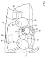
- Fig. 1 is a perspective view showing an inflated state of a kneebag and an arm-protecting airbag of the passenger protection device according to a first embodiment of the present invention
- Fig. 2(a) is a side view showing a state in which the airbag for the driver's seat is also inflated
- Fig. 2(b) is a cross sectional view taken along the line B-B in Fig. 2(a).
- the lateral direction represents the left-and-right direction of the motorvehicle
- the fore-and-aft direction represents the fore-and-aft directions of the motorvehicle.
- a steering column (not shown) is projected from an instrument panel 12 located forwardly of the driver's seat 10, and the steering column is surrounded by a steering column cover 14.
- the distal end of the steering shaft projecting from the steering column is attached with a steering wheel 16 and the steering wheel 16 is provided with an airbag device for the driver's seat 20 therein.
- the airbag device for the driver's seat 20 includes a retainer, an airbag 22 mounted on the retainer, an inflator for inflating the airbag 22, and a module cover 24 for covering the folded airbag 22.
- the airbag 22 is inflated, and the module cover 24 is broken, and the airbag 22 is inflated so as to cover the steering wheel 16.
- a kneebag device 30 is installed in the instrument panel 12 located downwardly of the steering column cover 14.
- An airbag (hereinafter referred to as kneebag) 32 of the kneebag device 30 is stored in a container-shaped retainer (kneebag retaining member) 34 provided in the instrument panel 12 in a folded state.
- a lid 36 is mounted on the retainer 34 so as to cover the bent kneebag 32.
- the lid 36 closes an opening 38 formed on the instrument panel 12 for inflation of the kneebag.
- a gas generator 40 for inflating the kneebag 32 is installed in the retainer 34. When the gas generator 40 is actuated, gas from the gas generator 40 is introduced into the kneebag 32, and the kneebag 32 is popped out through the opening 38 and is inflated in the interior of the vehicle while pushing the lid 36 to open.
- the kneebag 32 When the kneebag 32 is, as shown in Fig. 2(a), popped out and inflated through the opening 38, it is deployed upwardly along the front surface of the instrument panel 12, and covers the lower half of the instrument panel 12 facing toward the leg portions of the passenger sitting on the driver's seat.
- the upper portion of the kneebag 32 is adapted to spread up to the area near the lower portion of the steering column cover 14 in a state in which the kneebag 32 is completely inflated.
- a pair of arm-protecting airbags (hereinafter the arm-protecting airbag is referred to as armbag) 42, 44 are connected to the left and right side of the upper portion of the inflated kneebag 32.
- openings 46 for introducing gas into the respective armbags 42, 44 are formed at the lower portions of the respective armbags 42, 44, and the kneebag 32 is formed with openings 48 corresponding to the openings 46 for introducing gas from the gas generator 40 on the left and right side of the upper portion thereof.
- the respective armbags 42, 44 and the kneebag 32 are connected by joining the peripheral edges of these openings 46, 48 with each other by stitching or the like. Though these openings 46, 48 are formed on the surface of the kneebag 32 facing toward the passenger, they may be formed on the surfaces thereof facing toward the instrument panel 12 as well.
- the armbag 42 connected on the left side of the kneebag 32 is inflated so as to cover the left side area of the steering column cover 14 and the upper portion of a center console panel 50.
- the armbag 44 connected to the right side of the upper portion of the kneebag 32 is inflated so as to cover the right side area of the steering column cover 14.
- the respective armbags 42, 44 are folded and stored in the retainer 34 integrally with the kneebag 32.
- the gas generator 40 of the kneebag device and the gas generator (not shown) of the airbag device for the driver's seat are actuated, and thus the kneebag 32 and the airbag 22 are inflated by gas from them.
- the kneebag 32 pushes and opens the lid 36 and starts being inflated in the interior of the motorvehicle, and is inflated forwardly of the leg potions of the passenger sitting on the driver's seat as described above.
- the airbag 22 pushes and opens the module cover 24 and is deployed so as to cover the steering wheel 16, and inflated at the position forwardly of the face and the upper half body of the passenger.
- gas introduced from the gas generator 40 to the kneebag 32 flows or is injected through the kneebag 32 to the respective armbags 42, 44, whereby the armbags 42, 44 are inflated and deployed in the space on the left and right between the instrument panel 12 and the backside of the steering wheel 16, so as to receive the left and right arms of the passenger.
- the respective armbags 42, 44 since the armbags 42, 44 are connected to the kneebag 32 respectively, when in normal use, the respective armbags 42, 44 may be folded and stored in the kneebag device retainer 34 integrally with the kneebag 32.
- the respective armbags 42, 44 may be inflated integrally with the kneebag 32 by the gas generator 40 shared with the kneebag 32. This eliminates necessity of providing a separate retainer or the like for storing the gas generator for inflating the respective armbags 42, 44 and the respective armbags 42, 44, and thus simplifies the structure, which is very economical.
- the armbags 42, 44 and the kneebag 32 are provided separately and joined integrally with each other by stitching or the like in the present embodiment, as in the passenger protecting device as shown in the following Fig. 3, the structure in which the armbag and the kneebag are formed integrally from a continuous ground fabric (panel) in advance may be employed.
- Fig. 3 is a perspective view of the kneebag in the passenger protecting device according to a second embodiment of the present invention in a state of being inflated.
- the passenger protecting device shown in Fig. 3 is constructed in such a manner that armbags 42A, 44A overhanging from a kneebag 32A so as to be inflated forwardly of the left and right arms of the passenger on the driver's seat are provided on the left and right sides of the upper portion of the kneebag 32A in the inflated state.
- the respective arm bags 42A, 44A start to be inflated integrally with the kneebag 32A by gas from the gas generator 40.
- the armbag 42A is inflated so as to cover the left side area of the steering column cover 14 and the upper portion of the center console panel 50 along the front surface of the upper portion of the instrument panel 12, so that the left arm is received and protected.
- the armbag 44A is inflated so as to cover the right side area of the steering column cover 14 along the front surface of the upper portion of the instrument panel 12 so that the right arm is received and protected.
- the armbag device having a gas generator for inflating the armbag may be provided separately from the kneebag device or the airbag device as passenger protecting devices shown in the following Fig 4 or Fig 5.
- Fig. 4 and Fig. 5 are perspective views of the passenger protecting device according to third and fourth embodiments of the present invention showing a state in which the armbags are inflated.
- the passenger protection device in Fig. 4 includes an armbag 52 formed independently of the kneebag or airbag, and an armbag device having a gas generator (not shown) for inflating the armbag 52 in the instrument panel 12 located downwardly of the steering column cover 14.
- the reference numeral 54 indicates an opening for popping out the armbag for inflation. The opening 54 is normally closed by the lid.
- the armbag 52 in case of motorvehicle collision, is inflated through the opening 54 into the interior of the motorvehicle by gas from the gas generator and is spread substantially in the shape of a letter U, i.e. U-like which extends upward on the left and right side, along the front surface of the instrument panel 12.
- the left half thereof is inflated so as to cover the left side area of the steering column cover 14 and the upper portion of the center console panel 50 so that the left arm of the passenger is received and protected
- the right half thereof is inflated so as to cover the right side area of the steering column cover 14 so that the right arm of the passenger is received and protected.
- an armbag device including an armbag 56 provided independently of the kneebag and the airbag and a gas generator (not shown) for inflating the armbag 56 are provided on the instrument panel 12 above the steering column cover 14.
- the reference numeral 58 indicates an opening for popping out the armbag for inflation.
- the opening 58 is normally closed by the lid.
- the armbag device may be provided inside the steering column cover 14.
- the armbag 56 in case of motorvehicle collision, is inflated through the opening 58 into the interior of the motorvehicle by gas from the gas generator and is spread substantially in the shape of an inverted letter U, which extends upward on the left and right side, along the front surface of the upper portion of the instrument panel 12.
- the left half thereof is inflated so as to cover the left side area of the steering column cover 14 and the upper portion of the center console panel 50 so that the left arm of the passenger is received and protected
- the right half thereof is inflated so as to cover the right side area of the steering column cover 14 so that the right arm of the passenger is received and protected.
- the left halves of the armbags 54, 56 to be inflated forwardly of the left arm of the passenger on the driver's seat and the right halves to be inflated forwardly of the right arm of the passenger on the driver's seat are formed integrally.
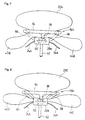
- Fig. 6 and Fig. 7 are a perspective view of the airbag and the armbag in the passenger protecting device in the inflated state, and a drawing of the steering wheel viewed from below according to a fifth embodiment of the present invention respectively.
- a pair of armbags 42B, 44B that may be inflated forwardly of the left and right arms of the passenger on the driver's seat are respectively connected to both left and right sides of the rear surface (the surface opposite from the passenger) of an airbag 22A in the inflated state, and the armbags 42B, 44B are in communication with the airbag 22A through a communication port 61 respectively.
- the airbag 22A is folded integrally with the armbags 42B, 44B and covered by a module cover 24A (Fig. 7) of the airbag device 20A.
- the airbag 22A in case of emergency such as motorvehicle collision and the like, the airbag 22A is inflated by gas from the gas generator 60 of the airbag device 20A, pushes and opens the module cover 24A, and is spread so as to cover the front surface of the steering wheel 16A.
- a steering wheel 16A includes three spoke members 66 extending from a wheel member 64 toward the center thereof.
- the airbag 22A and the respective armbags 42B, 44B are adapted to be inflated integrally by a single gas generator 60 by connecting the armbags 42B, 44B to the airbag 22A, and bringing them into communication with each other via the communication port 61 in the passenger protecting device in Figs. 6 and 7, it is also possible to provide an airbag 22C and armbags 42C, 44C separately and connect them respectively to the gas generator 60 of an airbag device 20B so as to be capable of introducing gas therefrom as in the passenger protecting device shown in Fig 8.
- Fig. 9 is a perspective view of the kneebag and the armbags according to a seventh embodiment of the present invention in the inflated state
- Fig. 10 is a side view of the same.
- a dash panel 71 located forwardly of the front passenger seat is provided with a kneebag device 74 below a globe box 72.
- the kneebag device 74 includes a kneebag 70, a gas generator (not shown) for inflating the kneebag 70, a container (not shown) for storing the folded kneebag 70, a lid 76 for covering the front surface of the container and so on.
- a pair of armbags 42D, 44D that can be inflated at the positions forwardly of the left and right arms of the passenger on the front passenger seat are respectively connected to the left and right sides of the lower portion of the kneebag 70 in the inflated state.
- the respective armbags 42D, 44D and the kneebag 70 are in communication with each other via a communication port 78, and the armbags 42D, 44D and the kneebag 70 are inflated integrally by gas introduced from the gas generator into the kneebag 70, which further flows into the respective armbags 42D, 44D via the communication port 78.
- the kneebag 70 and the armbags 42D, 44D receive the legs and the left and right arms of the passenger and protects the same respectively.
- An airbag device for the front passenger seat for receiving the upper half body of the passenger on the front passenger seat is provided upwardly of the kneebag device 74.
- the reference numeral 80 designates an inflated airbag for the front passenger seat.
- a passenger protecting device for protecting the passenger by receiving the passenger's arm by the airbag in case of collision is provided.
Landscapes
- Engineering & Computer Science (AREA)
- Mechanical Engineering (AREA)
- Air Bags (AREA)
Applications Claiming Priority (2)
| Application Number | Priority Date | Filing Date | Title |
|---|---|---|---|
| JP2001392078A JP2003182500A (ja) | 2001-12-25 | 2001-12-25 | 乗員保護装置 |
| JP2001392078 | 2001-12-25 |
Publications (2)
| Publication Number | Publication Date |
|---|---|
| EP1338478A1 true EP1338478A1 (fr) | 2003-08-27 |
| EP1338478B1 EP1338478B1 (fr) | 2005-05-25 |
Family
ID=19188589
Family Applications (1)
| Application Number | Title | Priority Date | Filing Date |
|---|---|---|---|
| EP02023739A Expired - Lifetime EP1338478B1 (fr) | 2001-12-25 | 2002-10-23 | Dispositif de protection du passager |
Country Status (4)
| Country | Link |
|---|---|
| US (1) | US20030116945A1 (fr) |
| EP (1) | EP1338478B1 (fr) |
| JP (1) | JP2003182500A (fr) |
| DE (1) | DE60204277T2 (fr) |
Cited By (1)
| Publication number | Priority date | Publication date | Assignee | Title |
|---|---|---|---|---|
| DE102016014877A1 (de) | 2016-12-14 | 2017-06-29 | Daimler Ag | Halteanordnung eines Knie-Airbags an einem Handschuhfachgehäuse für einen Kraftwagen |
Families Citing this family (57)
| Publication number | Priority date | Publication date | Assignee | Title |
|---|---|---|---|---|
| JP4119155B2 (ja) * | 2002-04-22 | 2008-07-16 | 本田技研工業株式会社 | 小型車両におけるエアバッグ装置 |
| JP2005239128A (ja) * | 2004-02-24 | 2005-09-08 | Takata Corp | ツインエアバッグ装置 |
| JP4333463B2 (ja) * | 2004-04-20 | 2009-09-16 | スズキ株式会社 | エアバッグ装置付小型滑走艇 |
| JP4412046B2 (ja) * | 2004-04-26 | 2010-02-10 | スズキ株式会社 | エアバッグ装置付スノーモービル |
| US7070201B2 (en) | 2004-06-07 | 2006-07-04 | Cis Tech, Llc | Low risk deployment passenger airbag system |
| US20070024036A1 (en) * | 2004-11-15 | 2007-02-01 | Seung-Jae Song | Low risk deployment passenger airbag system |
| US7731229B2 (en) * | 2004-11-15 | 2010-06-08 | Cis Tech, Llc | Low risk deployment passenger airbag system with knee protection |
| US7328913B2 (en) * | 2004-11-15 | 2008-02-12 | Cis Tech, Llc | Low risk deployment passenger airbag system |
| DE102004062570A1 (de) * | 2004-12-24 | 2006-07-13 | Autoliv Development Ab | Schutzeinrichtung für Fahrzeuginsassen sowie Verfahren zur Fertigung eines mehrkammerigen Gassackes |
| JP2006297958A (ja) * | 2005-04-15 | 2006-11-02 | Takata Corp | エアバッグおよびエアバッグ装置 |
| JP2006298119A (ja) * | 2005-04-19 | 2006-11-02 | Takata Corp | エアバッグ装置、乗員保護システム、車両 |
| JP4591190B2 (ja) * | 2005-05-11 | 2010-12-01 | トヨタ自動車株式会社 | 運転席用エアバッグ装置 |
| JP4760194B2 (ja) * | 2005-07-29 | 2011-08-31 | タカタ株式会社 | エアバッグ及びエアバッグ装置 |
| JP4432932B2 (ja) | 2006-05-09 | 2010-03-17 | トヨタ自動車株式会社 | 車両用ニーエアバッグ装置及び車両用ニーエアバッグの展開方法 |
| DE102006022078B4 (de) * | 2006-05-11 | 2016-06-02 | Trw Automotive Gmbh | Gassack und Fahrzeuginsassen-Rückhaltevorrichtung |
| US7758069B2 (en) * | 2006-05-18 | 2010-07-20 | Autoliv Asp, Inc. | Knee airbag and restraint system for suppressing deployment of head/torso airbag |
| JP4661693B2 (ja) * | 2006-06-02 | 2011-03-30 | 豊田合成株式会社 | 助手席用エアバッグ |
| JP2008114703A (ja) * | 2006-11-02 | 2008-05-22 | Toyota Motor Corp | コラム付けニーエアバッグ装置 |
| JP4235222B2 (ja) * | 2006-11-02 | 2009-03-11 | トヨタ自動車株式会社 | コラム付けニーエアバッグ装置 |
| US8215671B2 (en) * | 2007-02-14 | 2012-07-10 | Autoliv Development Ab | Air-bag for a motor vehicle |
| JP4609450B2 (ja) * | 2007-05-07 | 2011-01-12 | トヨタ自動車株式会社 | 車両用ステアリング装置 |
| US20090160171A1 (en) * | 2007-12-21 | 2009-06-25 | Cis Tech, Llc | Low risk deployment driver airbag system |
| JP2009292292A (ja) * | 2008-06-04 | 2009-12-17 | Toyoda Gosei Co Ltd | エアバッグ装置 |
| DE102009052691A1 (de) * | 2009-11-11 | 2011-05-12 | GM Global Technology Operations LLC, Detroit | Fahrzeugkabine mit Airbagsystem |
| US8376396B2 (en) * | 2010-01-15 | 2013-02-19 | Honda Motor Co., Ltd. | Multi-chamber knee airbag |
| DE102013002982A1 (de) * | 2013-02-20 | 2014-08-21 | Autoliv Development Ab | Gassacksystem für den Insassenschutz |
| JP5880489B2 (ja) * | 2013-06-25 | 2016-03-09 | トヨタ自動車株式会社 | 運転席用エアバッグ装置 |
| US9162645B2 (en) | 2013-12-20 | 2015-10-20 | Ford Global Technologies, Llc | High pressure airbag for oblique impact modes |
| US9340176B2 (en) * | 2014-03-13 | 2016-05-17 | Ford Global Technologies, Llc | Passenger airbag with secondary chamber |
| JP6326486B2 (ja) | 2014-03-31 | 2018-05-16 | オートリブ ディベロップメント エービー | 車両用エアバッグ装置 |
| US10059299B2 (en) | 2014-04-11 | 2018-08-28 | Autoliv Development Ab | Airbag device |
| US9561774B2 (en) * | 2014-04-24 | 2017-02-07 | Ford Global Technologies, Llc | Winged driver airbag |
| US9713998B2 (en) | 2014-04-24 | 2017-07-25 | Ford Global Technologies, Llc | Corrugated passenger airbag |
| US9969349B2 (en) * | 2014-04-24 | 2018-05-15 | Ford Global Technologies, Llc | Passenger airbag with extended base |
| WO2015162943A1 (fr) | 2014-04-25 | 2015-10-29 | オートリブ ディベロップメント エービー | Dispositif à coussin gonflable de sécurité |
| JP6299477B2 (ja) * | 2014-06-23 | 2018-03-28 | トヨタ自動車株式会社 | 車両用エアバッグ装置 |
| JP6345241B2 (ja) | 2014-06-25 | 2018-06-20 | オートリブ ディベロップメント エービー | エアバッグ装置 |
| US10023144B2 (en) | 2014-06-30 | 2018-07-17 | Autoliv Development Ab | Airbag device |
| US10358106B2 (en) | 2014-08-04 | 2019-07-23 | Autoliv Development Ab | Airbag apparatus |
| JP6365327B2 (ja) | 2014-08-12 | 2018-08-01 | 豊田合成株式会社 | 助手席用エアバッグ装置 |
| JP6237535B2 (ja) * | 2014-08-25 | 2017-11-29 | 豊田合成株式会社 | 下肢保護用エアバッグ |
| US9555762B2 (en) * | 2014-08-29 | 2017-01-31 | Nihon Plast Co., Ltd. | Airbag device for motor vehicle |
| JP6383303B2 (ja) | 2015-02-24 | 2018-08-29 | マツダ株式会社 | エアバッグ装置 |
| JP6554917B2 (ja) * | 2015-06-05 | 2019-08-07 | Joyson Safety Systems Japan株式会社 | 運転席用エアバッグ及び運転席用エアバッグ装置 |
| US9758121B2 (en) * | 2015-09-15 | 2017-09-12 | Autoliv Asp, Inc. | Supplemental airbags and related airbag support systems |
| KR101756005B1 (ko) * | 2016-04-04 | 2017-07-20 | 현대자동차주식회사 | 차량용 전방 에어백 및 그 제어방법 |
| US9676362B1 (en) * | 2016-04-15 | 2017-06-13 | Ford Global Technologies, Llc | Multi-chambered airbag with controlled pressure differentials |
| US9663060B1 (en) * | 2016-04-15 | 2017-05-30 | Ford Global Technologies, Llc | Multi-chambered airbag with controlled pressure differentials |
| US9676363B1 (en) * | 2016-04-15 | 2017-06-13 | Ford Global Technologies, Llc | Multi-chambered airbag with controlled pressure differentials |
| JP6914074B2 (ja) * | 2017-03-29 | 2021-08-04 | 豊田合成株式会社 | ステアリングホイール用エアバッグ |
| US10457243B2 (en) * | 2017-06-01 | 2019-10-29 | Autoliv Asp, Inc. | Knee airbag assemblies |
| JP6766763B2 (ja) * | 2017-06-27 | 2020-10-14 | 豊田合成株式会社 | エアバッグ装置 |
| US11345305B2 (en) * | 2018-09-26 | 2022-05-31 | Trw Vehicle Safety Systems Inc. | Adaptive airbag for protecting occupants in a vehicle |
| JP2020090259A (ja) * | 2018-12-07 | 2020-06-11 | トヨタ自動車株式会社 | エアバッグ装置 |
| US10974684B2 (en) * | 2019-03-01 | 2021-04-13 | Autoliv Asp, Inc. | Multi-chambered driver-side airbag assemblies |
| US11332093B2 (en) * | 2020-03-30 | 2022-05-17 | Ford Global Technologies, Llc | Airbag extending annularly around rotational axis of steering wheel |
| JP2024168630A (ja) * | 2023-05-24 | 2024-12-05 | 株式会社Subaru | エアバッグ装置 |
Citations (5)
| Publication number | Priority date | Publication date | Assignee | Title |
|---|---|---|---|---|
| US3747952A (en) * | 1971-09-17 | 1973-07-24 | R Graebe | Protective device |
| JPS6364851A (ja) * | 1986-09-06 | 1988-03-23 | Michihiro Kannonji | エアバツク |
| US6024377A (en) * | 1997-09-22 | 2000-02-15 | Breed Automotive Technology, Inc. | Low mount airbag deployment system |
| DE19860933A1 (de) * | 1998-12-30 | 2000-07-13 | Petri Ag | Airbagmodul |
| EP1086860A2 (fr) * | 1999-09-20 | 2001-03-28 | TRW Occupant Restraint Systems GmbH & Co. KG | Dispositif de retenue pour occupant de véhicule |
Family Cites Families (11)
| Publication number | Priority date | Publication date | Assignee | Title |
|---|---|---|---|---|
| US3981518A (en) * | 1975-05-05 | 1976-09-21 | Liberty Mutual Insurance Company | Vehicle restraint system |
| US4265468A (en) * | 1979-07-03 | 1981-05-05 | General Motors Corporation | Inflatable restraint system |
| US4300894A (en) * | 1979-12-03 | 1981-11-17 | General Motors Corporation | Method of making L-shaped inflatable restraint cushion |
| DE4307969A1 (de) * | 1993-03-12 | 1994-09-15 | Trw Repa Gmbh | Fahrerseitiges Gassack-Rückhaltesystem für Fahrzeuge |
| JP3316315B2 (ja) * | 1994-09-06 | 2002-08-19 | タカタ株式会社 | 助手席用エアバッグ装置 |
| JP2962225B2 (ja) * | 1996-04-08 | 1999-10-12 | 三菱自動車工業株式会社 | 側面衝突用エアバッグ |
| JP3685873B2 (ja) * | 1996-06-19 | 2005-08-24 | 本田技研工業株式会社 | 自動二輪車用エアバッグ装置 |
| DE19725558C2 (de) * | 1997-06-12 | 2001-11-29 | Petri Ag | Airbag-Rückhaltesystem |
| DE19738842A1 (de) * | 1997-09-05 | 1999-03-18 | Volkswagen Ag | Insassenschutzvorrichtung für ein Kraftfahrzeug |
| DE19932696C1 (de) * | 1999-07-15 | 2000-09-07 | Daimler Chrysler Ag | Insassenschutzvorrichtung mit zumindest zwei mit Gas auffüllbaren Airbags |
| JP3746193B2 (ja) * | 2000-11-28 | 2006-02-15 | 本田技研工業株式会社 | エアバッグ装置 |
-
2001
- 2001-12-25 JP JP2001392078A patent/JP2003182500A/ja active Pending
-
2002
- 2002-10-23 EP EP02023739A patent/EP1338478B1/fr not_active Expired - Lifetime
- 2002-10-23 DE DE60204277T patent/DE60204277T2/de not_active Expired - Lifetime
- 2002-12-02 US US10/307,327 patent/US20030116945A1/en not_active Abandoned
Patent Citations (5)
| Publication number | Priority date | Publication date | Assignee | Title |
|---|---|---|---|---|
| US3747952A (en) * | 1971-09-17 | 1973-07-24 | R Graebe | Protective device |
| JPS6364851A (ja) * | 1986-09-06 | 1988-03-23 | Michihiro Kannonji | エアバツク |
| US6024377A (en) * | 1997-09-22 | 2000-02-15 | Breed Automotive Technology, Inc. | Low mount airbag deployment system |
| DE19860933A1 (de) * | 1998-12-30 | 2000-07-13 | Petri Ag | Airbagmodul |
| EP1086860A2 (fr) * | 1999-09-20 | 2001-03-28 | TRW Occupant Restraint Systems GmbH & Co. KG | Dispositif de retenue pour occupant de véhicule |
Non-Patent Citations (1)
| Title |
|---|
| PATENT ABSTRACTS OF JAPAN vol. 012, no. 289 (M - 728) 8 August 1988 (1988-08-08) * |
Cited By (1)
| Publication number | Priority date | Publication date | Assignee | Title |
|---|---|---|---|---|
| DE102016014877A1 (de) | 2016-12-14 | 2017-06-29 | Daimler Ag | Halteanordnung eines Knie-Airbags an einem Handschuhfachgehäuse für einen Kraftwagen |
Also Published As
| Publication number | Publication date |
|---|---|
| EP1338478B1 (fr) | 2005-05-25 |
| DE60204277T2 (de) | 2005-11-24 |
| JP2003182500A (ja) | 2003-07-03 |
| US20030116945A1 (en) | 2003-06-26 |
| DE60204277D1 (de) | 2005-06-30 |
Similar Documents
| Publication | Publication Date | Title |
|---|---|---|
| EP1338478B1 (fr) | Dispositif de protection du passager | |
| EP1318052B1 (fr) | Coussin gonflable | |
| US7163229B2 (en) | Occupant protection device and vehicle | |
| JP4119242B2 (ja) | 乗員保護装置用のガスバッグ | |
| EP1283136B1 (fr) | Dispositif de protection des jambes pour passager de véhicule | |
| US6435554B1 (en) | Knee bolster apparatus with center tether | |
| EP1714840B1 (fr) | Dispositif d'airbag, système de protection des passagers et véhicule | |
| EP0940302A1 (fr) | Dispositif d'airbag pour collision laterale d'une automobile | |
| US6471244B1 (en) | Airbag and airbag arrangement | |
| CN100590005C (zh) | 用于车辆的膝部安全气囊装置 | |
| JPH10119703A (ja) | 車輌乗員保護装置 | |
| EP1686017A1 (fr) | Coussin gonflable et son système | |
| KR100244541B1 (ko) | 차량 운전자의 보호장치 | |
| JP3807258B2 (ja) | 鞍乗型車両用エアバッグ装置 | |
| EP1479571A1 (fr) | Dispositif de protection des jambes d'un occupant | |
| US5562302A (en) | Inflatable vehicle occupant restraint | |
| US7980592B2 (en) | Bi-lobular air bag | |
| US8172260B2 (en) | Bi-lobular air bag | |
| US20210122317A1 (en) | Driver airbag | |
| US7669882B2 (en) | Airbag module | |
| US8186713B2 (en) | Vented air bag | |
| JP3991739B2 (ja) | エアバッグ、エアバッグ装置及びステアリング | |
| EP1266806A2 (fr) | Dispositif d'airbag | |
| GB2299061A (en) | Airbag arrangement for protecting against side impact | |
| WO2007055234A1 (fr) | Airbag et dispositif d’airbag |
Legal Events
| Date | Code | Title | Description |
|---|---|---|---|
| PUAI | Public reference made under article 153(3) epc to a published international application that has entered the european phase |
Free format text: ORIGINAL CODE: 0009012 |
|
| AK | Designated contracting states |
Designated state(s): AT BE BG CH CY CZ DE DK EE ES FI FR GB GR IE IT LI LU MC NL PT SE SK TR |
|
| AX | Request for extension of the european patent |
Extension state: AL LT LV MK RO SI |
|
| 17P | Request for examination filed |
Effective date: 20040129 |
|
| 17Q | First examination report despatched |
Effective date: 20040305 |
|
| AKX | Designation fees paid |
Designated state(s): DE FR GB SE |
|
| GRAP | Despatch of communication of intention to grant a patent |
Free format text: ORIGINAL CODE: EPIDOSNIGR1 |
|
| GRAS | Grant fee paid |
Free format text: ORIGINAL CODE: EPIDOSNIGR3 |
|
| GRAA | (expected) grant |
Free format text: ORIGINAL CODE: 0009210 |
|
| AK | Designated contracting states |
Kind code of ref document: B1 Designated state(s): DE FR GB SE |
|
| REG | Reference to a national code |
Ref country code: GB Ref legal event code: FG4D |
|
| REG | Reference to a national code |
Ref country code: IE Ref legal event code: FG4D |
|
| REF | Corresponds to: |
Ref document number: 60204277 Country of ref document: DE Date of ref document: 20050630 Kind code of ref document: P |
|
| REG | Reference to a national code |
Ref country code: SE Ref legal event code: TRGR |
|
| ET | Fr: translation filed | ||
| PLBE | No opposition filed within time limit |
Free format text: ORIGINAL CODE: 0009261 |
|
| STAA | Information on the status of an ep patent application or granted ep patent |
Free format text: STATUS: NO OPPOSITION FILED WITHIN TIME LIMIT |
|
| 26N | No opposition filed |
Effective date: 20060228 |
|
| PGFP | Annual fee paid to national office [announced via postgrant information from national office to epo] |
Ref country code: SE Payment date: 20071004 Year of fee payment: 6 |
|
| PGFP | Annual fee paid to national office [announced via postgrant information from national office to epo] |
Ref country code: FR Payment date: 20071009 Year of fee payment: 6 |
|
| EUG | Se: european patent has lapsed | ||
| REG | Reference to a national code |
Ref country code: FR Ref legal event code: ST Effective date: 20090630 |
|
| PG25 | Lapsed in a contracting state [announced via postgrant information from national office to epo] |
Ref country code: FR Free format text: LAPSE BECAUSE OF NON-PAYMENT OF DUE FEES Effective date: 20081031 |
|
| PG25 | Lapsed in a contracting state [announced via postgrant information from national office to epo] |
Ref country code: SE Free format text: LAPSE BECAUSE OF NON-PAYMENT OF DUE FEES Effective date: 20081024 |
|
| PGFP | Annual fee paid to national office [announced via postgrant information from national office to epo] |
Ref country code: GB Payment date: 20131023 Year of fee payment: 12 Ref country code: DE Payment date: 20131016 Year of fee payment: 12 |
|
| REG | Reference to a national code |
Ref country code: DE Ref legal event code: R119 Ref document number: 60204277 Country of ref document: DE |
|
| GBPC | Gb: european patent ceased through non-payment of renewal fee |
Effective date: 20141023 |
|
| PG25 | Lapsed in a contracting state [announced via postgrant information from national office to epo] |
Ref country code: DE Free format text: LAPSE BECAUSE OF NON-PAYMENT OF DUE FEES Effective date: 20150501 Ref country code: GB Free format text: LAPSE BECAUSE OF NON-PAYMENT OF DUE FEES Effective date: 20141023 |