EP1338484A1 - Dispositif de protection des piétons en cas de choc frontal avec une véhicule automobile et véhicule equipé d'un tel dispositif - Google Patents
Dispositif de protection des piétons en cas de choc frontal avec une véhicule automobile et véhicule equipé d'un tel dispositif Download PDFInfo
- Publication number
- EP1338484A1 EP1338484A1 EP03290204A EP03290204A EP1338484A1 EP 1338484 A1 EP1338484 A1 EP 1338484A1 EP 03290204 A EP03290204 A EP 03290204A EP 03290204 A EP03290204 A EP 03290204A EP 1338484 A1 EP1338484 A1 EP 1338484A1
- Authority
- EP
- European Patent Office
- Prior art keywords
- sleeve
- protection device
- pedestrian protection
- balls
- flange
- Prior art date
- Legal status (The legal status is an assumption and is not a legal conclusion. Google has not performed a legal analysis and makes no representation as to the accuracy of the status listed.)
- Granted
Links
- 230000004913 activation Effects 0.000 claims description 16
- 230000000903 blocking effect Effects 0.000 claims description 11
- 230000000694 effects Effects 0.000 claims description 9
- 230000006835 compression Effects 0.000 claims description 5
- 238000007906 compression Methods 0.000 claims description 5
- 238000006073 displacement reaction Methods 0.000 claims description 5
- 230000003028 elevating effect Effects 0.000 abstract description 5
- 208000031968 Cadaver Diseases 0.000 description 2
- 208000027418 Wounds and injury Diseases 0.000 description 1
- 230000003213 activating effect Effects 0.000 description 1
- 230000000295 complement effect Effects 0.000 description 1
- 230000006378 damage Effects 0.000 description 1
- 230000000994 depressogenic effect Effects 0.000 description 1
- 238000001514 detection method Methods 0.000 description 1
- 238000005553 drilling Methods 0.000 description 1
- 230000002401 inhibitory effect Effects 0.000 description 1
- 208000014674 injury Diseases 0.000 description 1
- 230000004807 localization Effects 0.000 description 1
- 230000001681 protective effect Effects 0.000 description 1
- 230000001960 triggered effect Effects 0.000 description 1
Images

Classifications
-
- B—PERFORMING OPERATIONS; TRANSPORTING
- B60—VEHICLES IN GENERAL
- B60R—VEHICLES, VEHICLE FITTINGS, OR VEHICLE PARTS, NOT OTHERWISE PROVIDED FOR
- B60R21/00—Arrangements or fittings on vehicles for protecting or preventing injuries to occupants or pedestrians in case of accidents or other traffic risks
- B60R21/34—Protecting non-occupants of a vehicle, e.g. pedestrians
- B60R21/38—Protecting non-occupants of a vehicle, e.g. pedestrians using means for lifting bonnets
-
- E—FIXED CONSTRUCTIONS
- E05—LOCKS; KEYS; WINDOW OR DOOR FITTINGS; SAFES
- E05D—HINGES OR SUSPENSION DEVICES FOR DOORS, WINDOWS OR WINGS
- E05D3/00—Hinges with pins
- E05D3/02—Hinges with pins with one pin
- E05D3/022—Hinges with pins with one pin allowing an additional lateral movement, e.g. for sealing
-
- E—FIXED CONSTRUCTIONS
- E05—LOCKS; KEYS; WINDOW OR DOOR FITTINGS; SAFES
- E05Y—INDEXING SCHEME ASSOCIATED WITH SUBCLASSES E05D AND E05F, RELATING TO CONSTRUCTION ELEMENTS, ELECTRIC CONTROL, POWER SUPPLY, POWER SIGNAL OR TRANSMISSION, USER INTERFACES, MOUNTING OR COUPLING, DETAILS, ACCESSORIES, AUXILIARY OPERATIONS NOT OTHERWISE PROVIDED FOR, APPLICATION THEREOF
- E05Y2900/00—Application of doors, windows, wings or fittings thereof
- E05Y2900/50—Application of doors, windows, wings or fittings thereof for vehicles
- E05Y2900/53—Type of wing
- E05Y2900/536—Hoods
Definitions
- the present invention relates to a protective device pedestrians in the event of a frontal collision with a vehicle automobile.
- a vehicle automobile comprising means for raising the part rear cover that can be activated when a pedestrian impact is detected in the front of the vehicle, so that move the impact zone between the pedestrian's head and the hood rigid elements located under the hood, in order to reduce the the severity of the pedestrian's impact on the hood, particularly at of the head.
- a hood provided with such means elevation is commonly referred to as “active hood” by the skilled person.
- the pedestrian's head In the event of a frontal impact of a motor vehicle with a pedestrian, the pedestrian's head usually comes into contact with the cover. During the impact of the pedestrian's head on the hood, it is produces a depression of the hood until a possible impact with rigid elements located under the hood such as the battery, carrier elements ... Similarly, it can occur a direct impact with rigid areas of the hood. These impacts rigid elements are the main cause of death or serious injury to pedestrians overturned.
- Pedestrian protection devices comprising means for raising the rear portion of the hood that can only be used once or whose subsequent reuse requires parts replacement costly and / or heavy intervention in after-sales service to restore these elevation means to operate again when needed.
- the purpose of the present invention is to overcome the disadvantages by proposing a device for pedestrian protection particularly suitable for vehicles having to meet strict reparability criteria and to which means of elevation, after activation, must again be brought back into working order, so relatively easy.
- the present invention relates to a device for pedestrian protection in the event of a frontal collision with a vehicle automobile comprising means for raising the part rear cover that can be activated when a pedestrian impact is detected in the front of the vehicle, so that move the impact zone between the pedestrian's head and the hood rigid elements located under the hood, characterized in that that the elevation means are shaped to be rearmed manually after activation, so as to be new operational.
- the invention also relates to a motor vehicle including a pedestrian protection device with the previous characteristics.
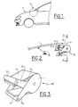
- FIG. 1 shows a motor vehicle provided with a hood 1.
- the vehicle is equipped with a pedestrian protection in the event of frontal impact.
- this device comprises ME elevation means situated in zone D, of the rear part of hood 1, suitable for be activated when a pedestrian impact is detected in the frontal of the vehicle.
- ME elevation means situated in zone D, of the rear part of hood 1, suitable for be activated when a pedestrian impact is detected in the frontal of the vehicle.
- FIG. 1 A detailed view of these means elevation ME is shown in FIG.
- elevation ME may be arranged in duplicate on the vehicle, ie on each of its sides, by example in the vicinity of conventional joints connecting the Hood 1 to the vehicle structure.
- the elevation means ME comprise a sleeve 3, of generally cylindrical shape, closed to its ends by a pair of flanges 4, 5.
- the latter 4, 5 are axially connected and rotatably mounted relative to the sleeve 3.
- the flanges 4, 5 can pivot relative to the sleeve 3 from an initial angular position in which they can be maintained in position by means of blockages 6-8 disengageable, up to an angular position final, to which they can be trained by means 9 interposed between the sleeve 3 and the flanges 4, 5, as will be described below.
- These return means 9 consist of a spring 9 to blades, counting for example two blades, having the shape of a U.
- the central part of this U wife at least partially the outer cylindrical surface of the sleeve 3 while the free ends of the spring 9 cooperate in support on two axes 12, 13 substantially parallel to the sleeve 3, respectively connected to sleeve 3 and to flanges 4, 5, so that the action of the leaf spring 9 tends to separate the axes 12, 13 from each other ( Figures 2 and 3).
- the axes 12, 13 are respectively connected to the sleeve 3 and flanges 4, 5, respectively via a first pair 32 of lever arms and a second pair 52 of lever arm.
- the second pair 52 of lever arms can be constituted by respective extensions formed on each of the flanges 4, 5, as can be seen in FIGS. and 3.
- axis 13 is based on the structure of the vehicle, being articulated on it, and that the axis 12 supports hood hinges 1 or an adjacent element 14 on which the cover 1 is pivotally mounted (Figure 2), will understand that the relative spacing of the axes 12, 13 causes a corresponding elevation of the rear part of the hood 1.
- the sleeve 3 is extended at one of its ends by a cylindrical portion 31, housed in the sleeve 3 so as to form a hem inside.
- a 3rd space of general shape cylindrical, is intended to radially separate the body outside the sleeve 3 of this cylindrical portion 31.
- a sleeve 6 slidably mounted axially relative to the sleeve 3 and / or the cylindrical portion 31 can come to occupy this 3rd space more or less completely moving.
- a bearing 8 is pivotally mounted to the inside of the cylindrical portion 31, this bearing 8 being linked to one of the flanges 4, 5 by means 81 ensuring a pivot connection with one-way rotation.
- Such a link, type ratchet wheel allows indeed a drive in a given direction of rotation while the connection is free in the reverse. It will be specified that the training between level 8 and the flange 5 is provided in the direction corresponding to the pivoting the flanges 4, 5 to their angular position final, tending to separate the axes 12, 13 from each other.
- the blocking means 6-8 comprise a a plurality of balls 7 able to move in bores 31p corresponding formed radially in the portion cylindrical 31 mentioned above.
- the ball-bores couples can be spread on the circumference of the portion 31.
- a single ball and associated drilling may be provided and prove sufficient for the operation of the locking means.
- the balls 7 can occupy a first blocking position, in which the balls 7 are partially engaged in concave housings 8c respective of the bearing 8, extending radially holes 31p, so as to prevent the relative pivoting of the flange 5 relative to the sleeve 3, to its final angular position, ie in the direction tending to move the axes 12, 13 away from each other (FIG. 4A).
- the balls 7 are partially engaged in these housings 8c, they are arranged astride between the piercing 31 and the 8c, so as to form an obstacle to relative pivoting of the flange 5 and the sleeve 3.
- concave housings 8c can may be formed by spherical shaped depressions.
- the balls 7 can occupy a second unlocking position in which the balls 7 are evacuated 8c of level 8, so as to authorize the relative pivoting of sleeve 3 with respect to bearing 8 and flange 5 (FIG. 5A).
- the passage of the balls 7 from their blocking position to their unlocking position corresponds to the disengagement of the means blocking 6-8.
- the bushing 6 is shaped so as to slide axially by relative to the sleeve 3 from an axial position in which the sleeve 6 cooperates in abutment with the balls 7 so as to imprison in their blocking position (Figure 4A), and a final axial position, in which the balls 7 can be introduced in areas of evacuation 6e spared radially in the sleeve 6, so as to present itself in their unlocking position ( Figure 4B).
- These evacuation areas 6th may be formed by radially formed bores in the body of the socket 6. As illustrated in FIGS.
- these bores 6e can be inclined with respect to the axis longitudinal of the sleeve 6, for example an angle of the order 45 °, so that each ball 7 is introduced progressively in the corresponding bore 6, being guided as the bushing 6 is its final axial position.
- an electromagnet 10 shown in FIGS. 4A and 4B.
- This electromagnet has the effect of a permanent magnet suitable to keep the socket pressed against it in its position initial axial.
- the attraction effect of the permanent magnet is inhibited, so that the sleeve is only subjected to the action of a compression spring 11 acting on it to make it slide from its initial axial position to its axial position final.
- the electromagnet 10 is supported by one of the flanges 4, 5.
- This flange 4 also offers a bearing surface and / or spring guide 11.
- the following elevation means ME the invention are shaped to be rearmed manually following their activation, so as to be again operational. That is, after an activation, they can be restored to their original state without any change of by a relatively simple manual intervention.
- the locking means 6-8 may indeed be manually reset to block again in rotation of the flanges 4, 5 with respect to the sleeve 3.
- Manual displacement means of the sleeve 6 are indeed intended to bring it back to its axial position initial.
- these means of moving can include a window 3f arranged in the body of the sleeve 3 (FIGS. 4A, 4B and 5), by which an operator can introduce a conventional tool, such as a screwdriver, in order to push the sleeve 6 to an axial position in the field of action of the electromagnet 10. More precisely this axial position is such that the force of attraction of the electromagnet 10 outweighs the strength of compression of the spring 11, so that the sleeve 6 comes to press against the electromagnet 10, in its axial position initial. Note that the attraction effect of the electromagnet 10 will be restored beforehand, ie the signal electric sent to the electromagnet to inhibit this effect will have been cut.
- the flanges 4, 5 can then be repositioned in their initial angular position relative to the sleeve 3.
- the relative spacing between the axes 12, 13 must be restored to its original value, that is to say that the rear cover 1 must be repositioned in a conventional manner, while the spring 9 cooperating with the axes 12, 13 must to be coerced once again to cooperate with the axes 12, 13 in anticipation of a new activation of the means of elevation ME.
- complementary means can be employees to facilitate the intervention of an operator during the rearming ME elevation means.
- a removable link system 15 shown in dotted line at Figure 2 may be provided for connecting an advanced area of the hood 1 to the axis 13, so that the elevation of the front of the hood depressed by a lever effect the part rear of the hood 1 by stressing the spring 9.
- the means for manual movement of the sleeve 6 can be constituted by a central axis of the housing formed by the sleeve 3 and the flanges 4, 5, this axis being connected to the bushing 6 and being axially displaced during the activation of raising means ME, so as to have an end on which an operator can act directly under pressure to reposition it in its starting position.
- the two flanges can be dissociated from one another in rotation. So one of the flanges can simply be a cover closing one end of the sleeve, while the 12 and 13 are respectively carried by the other flange and by the sleeve.
Landscapes
- Engineering & Computer Science (AREA)
- Mechanical Engineering (AREA)
- Superstructure Of Vehicle (AREA)
- Lighting Device Outwards From Vehicle And Optical Signal (AREA)
- Motor Or Generator Frames (AREA)
- Body Structure For Vehicles (AREA)
- Road Signs Or Road Markings (AREA)
Abstract
Description
- les moyens d'élévation comprennent un manchon fermé à ses deux extrémités par une paire de flasques reliés axialement dont l'un au moins est monté à rotation avec ledit manchon autour de son axe longitudinal et peut pivoter par rapport au manchon depuis une position angulaire initiale dans laquelle il peut être maintenu en position via des moyens de blocage débrayables, jusqu'à une position angulaire finale, vers laquelle il peut être entraíné via des moyens de rappel interposés entre le manchon et le flasque,
- le manchon est prolongé à l'une de ses extrémités par une portion cylindrique logée dans le manchon de façon à former un ourlet intérieur, tandis qu'une douille est montée coulissante axialement par rapport au manchon et/ou la portion cylindrique, dans l'espace séparant radialement le corps du manchon de sa portion cylindrique intérieure,
- un palier monté pivotant à l'intérieur de la portion cylindrique, est lié au flasque par des moyens assurant une liaison pivot à sens unique de rotation, tels qu'une roue à rochet,
- une pluralité de billes aptes à se déplacer dans des perçages correspondants formés radialement dans la portion cylindrique peuvent occuper une première position de blocage, dans laquelle les billes sont partiellement engagées dans des logements concaves respectifs du palier, prolongeant radialement les perçages, de façon à empêcher le pivotement relatif du flasque par rapport au manchon, et une seconde position de déblocage dans laquelle les billes sont évacuées des logements du palier, de façon à autoriser le pivotement relatif du manchon par rapport au flasque, en considérant que le passage des billes de leur position de blocage à leur position de déblocage correspond au débrayage des moyens de blocage et corrélativement à l'activation des moyens d'élévation,
- la douille est conformée de façon à coulisser axialement par rapport au manchon depuis une position axiale initiale, dans laquelle la douille coopère en butée avec les billes de façon à les emprisonner dans leur position de blocage, et une position axiale finale, dans laquelle les billes peuvent au moins partiellement être introduites dans des zones d'évacuation ménagées radialement dans la douille, de façon à se présenter dans leur position de déblocage,
- la douille peut être maintenue dans sa position axiale initiale par l'attraction d'un électro-aimant ayant l'effet d'attraction d'un aimant permanent, tandis qu'un signal électrique reçu par l'électro-aimant aux fins d'inhiber cet effet peut libérer la douille afin de la disposer dans sa position axiale finale, sous l'action de moyens de rappel, tels qu'un ressort de compression,
- les moyens de rappel sont constitués d'un ressort à au moins une lame ayant la forme générale d'un U dont la partie centrale épouse partiellement la surface extérieure du manchon tandis que les extrémités libres du ressort coopèrent en appui sur deux axes sensiblement parallèles au manchon, solidaires respectivement du manchon et de l'un au moins des flasques, ces deux axes étant reliés au manchon et au flasque par deux bras de levier correspondants de sorte que l'action du ressort tende à écarter lesdits axes l'un de l'autre lorsque les moyens de blocage empêchant le pivotement du flasque par rapport au manchon sont débrayés,
- l'un des axes est monté à rotation sur la structure du véhicule tandis que l'autre supporte le capot ou un élément adjacent sur lequel le capot est monté pivotant,
- des moyens de déplacement manuels de la douille sont prévus pour la ramener dans sa position axiale initiale, suite à une activation des moyens d'élévation,
- les moyens de déplacement manuels de la douille comprennent une fenêtre ménagée dans le corps du manchon, par laquelle un outillage peut être acheminé pour repousser la douille vers sa position axiale initiale,
- la figure 1 est une vue schématique de la partie avant d'un véhicule automobile indiquant la localisation des moyens d'élévation appartenant au dispositif de protection des piétons selon l'invention.
- la figure 2 est une vue d'un détail de réalisation de la figure 1, illustrant les moyens d'élévation de la partie arrière du capot selon l'invention,
- la figure 3 est une vue en perspective des moyens d'élévation de la figure 2.
- les figures 4A et 4B sont des vues suivant la ligne de coupe A-A des moyens d'élévation de la figure 2, respectivement avant et après activation.
Claims (12)
- Dispositif de protection des piétons en cas de choc frontal avec un véhicule automobile comprenant des moyens d'élévation (ME) de la partie arrière du capot (1) aptes à être activés lorsqu'un choc piéton est détecté dans la partie frontale du véhicule, de manière à éloigner la zone d'impact entre la tête du piéton et le capot (1) des éléments rigides situés sous le capot (1), les moyens d'élévation (ME) étant conformés pour être réarmés manuellement suite à leur activation, de façon à être de nouveau opérationnels, caractérisé en ce que les moyens d'élévation (ME) comprennent un manchon (3) fermé à ses deux extrémités par une paire de flasques (4, 5) reliés axialement dont l'un (5) au moins est monté à rotation avec ledit manchon (3) autour de son axe longitudinal et peut pivoter par rapport au manchon (3) depuis une position angulaire initiale dans laquelle il peut être maintenu en position via des moyens de blocage (6-8) débrayables, jusqu'à une position angulaire finale, vers laquelle il peut être entraíné via des moyens de rappel (9) interposés entre le manchon (3) et le flasque (5).
- Dispositif de protection des piétons selon la revendication 1, caractérisé en ce que les flasques (4, 5) sont reliés axialement.
- Dispositif de protection des piétons selon la revendication 2, caractérisé en ce que le manchon (3) est prolongé à l'une de ses extrémités par une portion cylindrique (31) logée dans le manchon (3) de façon à former un ourlet intérieur, tandis qu'une douille (6) est montée coulissante axialement par rapport au manchon (3) et/ou la portion cylindrique (31), dans l'espace (3e) séparant radialement le corps du manchon (3) de sa portion cylindrique (31) intérieure.
- Dispositif de protection des piétons selon la revendication 3, caractérisé en ce qu'un palier (8) monté pivotant à l'intérieur de la portion cylindrique (31), est lié au flasque (5) par des moyens (81) assurant une liaison pivot à sens unique de rotation, tels qu'une roue à rochet.
- Dispositif de protection des piétons selon la revendication 4, caractérisé en ce qu'une pluralité de billes (7) aptes à se déplacer dans des perçages (31p) correspondants formés radialement dans la portion cylindrique (31) peuvent occuper une première position de blocage, dans laquelle les billes (7) sont partiellement engagées dans des logements concaves (8c) respectifs du palier (8), prolongeant radialement les perçages (31p), de façon à empêcher le pivotement relatif du flasque (5) par rapport au manchon (3), et une seconde position de déblocage dans laquelle les billes (7) sont évacuées des logements (8c) du palier (8), de façon à autoriser le pivotement relatif du manchon (3) par rapport au flasque (5), en considérant que le passage des billes (7) de leur position de blocage à leur position de déblocage correspond au débrayage des moyens de blocage (6-8) et corrélativement à l'activation des moyens d'élévation (ME).
- Dispositif de protection des piétons selon la revendication 5, caractérisé en ce que la douille (6) est conformée de façon à coulisser axialement par rapport au manchon (3) depuis une position axiale initiale, dans laquelle la douille (6) coopère en butée avec les billes (7) de façon à les emprisonner dans leur position de blocage, et une position axiale finale, dans laquelle les billes (7) peuvent au moins partiellement être introduites dans des zones d'évacuation (6e) ménagées radialement dans la douille (6), de façon à se présenter dans leur position de déblocage.
- Dispositif de protection des piétons selon la revendication 6, caractérisé en ce que la douille (6) peut être maintenue dans sa position axiale initiale par l'attraction d'un électro-aimant (10) ayant l'effet d'attraction d'un aimant permanent, tandis qu'un signal électrique reçu par l'électro-aimant (10) aux fins d'inhiber cet effet peut libérer la douille (6) afin de la disposer dans sa position axiale finale, sous l'action de moyens de rappel (11), tels qu'un ressort de compression.
- Dispositif de protection des piétons selon l'une quelconque des revendications 2 à 7, caractérisé en ce que les moyens de rappel (9) sont constitués d'un ressort à au moins une lame ayant la forme générale d'un U dont la partie centrale épouse partiellement la surface extérieure du manchon (3) tandis que les extrémités libres du ressort (9) coopèrent en appui sur deux axes (12, 13) sensiblement parallèles au manchon (3), solidaires respectivement du manchon (3) et de l'un (5) au moins des flasques (4, 5), ces deux axes (12, 13) étant reliés au manchon (3) et au flasque (5) par deux bras de levier (32, 52) correspondants de sorte que l'action du ressort (9) tende à écarter lesdits axes (12, 13) l'un de l'autre lorsque les moyens de blocage (6-8) empêchant le pivotement du flasque (5) par rapport au manchon (3) sont débrayés.
- Dispositif de protection des piétons selon la revendication 8, caractérisé en ce que l'un (13) des axes (12, 13) est monté à rotation sur la structure du véhicule tandis que l'autre (12) supporte le capot (1) ou un élément adjacent (14) sur lequel le capot est monté pivotant (1).
- Dispositif de protection des piétons selon l'une quelconque des revendications 6 à 9, caractérisé en ce que des moyens de déplacement manuels de la douille (6) sont prévus pour la ramener dans sa position axiale initiale, suite à une activation des moyens d'élévation (ME).
- Dispositif de protection des piétons selon la revendication 10, caractérisé en ce que les moyens de déplacement manuels de la douille (6) comprennent une fenêtre (3f) ménagée dans le corps du manchon (3), par laquelle un outillage peut être acheminé pour repousser la douille (6) vers sa position axiale initiale.
- Véhicule automobile, caractérisé en ce qu'il comprend un dispositif de protection des piétons selon l'une quelconque des revendications précédentes.
Applications Claiming Priority (2)
| Application Number | Priority Date | Filing Date | Title |
|---|---|---|---|
| FR0202181A FR2836105B1 (fr) | 2002-02-21 | 2002-02-21 | Dispositif de protection des pietons en cas de chocs frontal avec un vehicule automobile et vehicule equipe d'un tel dispositif |
| FR0202181 | 2002-02-21 |
Publications (2)
| Publication Number | Publication Date |
|---|---|
| EP1338484A1 true EP1338484A1 (fr) | 2003-08-27 |
| EP1338484B1 EP1338484B1 (fr) | 2006-11-29 |
Family
ID=27636367
Family Applications (1)
| Application Number | Title | Priority Date | Filing Date |
|---|---|---|---|
| EP03290204A Expired - Lifetime EP1338484B1 (fr) | 2002-02-21 | 2003-01-28 | Dispositif de protection des piétons en cas de choc frontal avec une véhicule automobile et véhicule equipé d'un tel dispositif |
Country Status (5)
| Country | Link |
|---|---|
| EP (1) | EP1338484B1 (fr) |
| AT (1) | ATE346774T1 (fr) |
| DE (1) | DE60309943T2 (fr) |
| ES (1) | ES2272907T3 (fr) |
| FR (1) | FR2836105B1 (fr) |
Cited By (1)
| Publication number | Priority date | Publication date | Assignee | Title |
|---|---|---|---|---|
| WO2004083007A1 (fr) * | 2003-03-17 | 2004-09-30 | Ise Innomotive Systems Europe Gmbh | Dispositif pour proteger des individus en cas de choc frontal intervenant sur une automobile |
Citations (3)
| Publication number | Priority date | Publication date | Assignee | Title |
|---|---|---|---|---|
| DE19712961A1 (de) * | 1997-03-27 | 1998-10-01 | Bayerische Motoren Werke Ag | Anordnung einer Frontklappe an einem Fahrzeug |
| DE19922454A1 (de) * | 1999-05-17 | 2000-11-30 | Edscha Ag | Fronthaubenanordnung |
| US20020011365A1 (en) * | 2000-07-19 | 2002-01-31 | Honda Giken Kogyo Kabushiki Kaisha | Vehicular hood device |
-
2002
- 2002-02-21 FR FR0202181A patent/FR2836105B1/fr not_active Expired - Fee Related
-
2003
- 2003-01-28 AT AT03290204T patent/ATE346774T1/de not_active IP Right Cessation
- 2003-01-28 ES ES03290204T patent/ES2272907T3/es not_active Expired - Lifetime
- 2003-01-28 EP EP03290204A patent/EP1338484B1/fr not_active Expired - Lifetime
- 2003-01-28 DE DE60309943T patent/DE60309943T2/de not_active Expired - Lifetime
Patent Citations (3)
| Publication number | Priority date | Publication date | Assignee | Title |
|---|---|---|---|---|
| DE19712961A1 (de) * | 1997-03-27 | 1998-10-01 | Bayerische Motoren Werke Ag | Anordnung einer Frontklappe an einem Fahrzeug |
| DE19922454A1 (de) * | 1999-05-17 | 2000-11-30 | Edscha Ag | Fronthaubenanordnung |
| US20020011365A1 (en) * | 2000-07-19 | 2002-01-31 | Honda Giken Kogyo Kabushiki Kaisha | Vehicular hood device |
Cited By (1)
| Publication number | Priority date | Publication date | Assignee | Title |
|---|---|---|---|---|
| WO2004083007A1 (fr) * | 2003-03-17 | 2004-09-30 | Ise Innomotive Systems Europe Gmbh | Dispositif pour proteger des individus en cas de choc frontal intervenant sur une automobile |
Also Published As
| Publication number | Publication date |
|---|---|
| DE60309943D1 (de) | 2007-01-11 |
| FR2836105B1 (fr) | 2004-04-30 |
| ES2272907T3 (es) | 2007-05-01 |
| FR2836105A1 (fr) | 2003-08-22 |
| ATE346774T1 (de) | 2006-12-15 |
| EP1338484B1 (fr) | 2006-11-29 |
| DE60309943T2 (de) | 2007-09-20 |
Similar Documents
| Publication | Publication Date | Title |
|---|---|---|
| EP1555171B1 (fr) | Lève capot à actionneur muni d'un système de verrouillage par crochet | |
| EP3581742B1 (fr) | Poignée de porte affleurante et son procédé de fonctionnement | |
| EP2616616B1 (fr) | Poignee d'ouvrant de vehicule comprenant une masse inertielle et un fusible | |
| EP1431136A1 (fr) | Dispositif de sécurité pour soulever un capot d'un véhicule automobile en cas de collision | |
| WO2012013599A1 (fr) | Poignee d'ouvrant de vehicule comprenant une partie de prehension | |
| FR2475688A1 (fr) | Dispositif d'effacement, (ou de mise en retrait) de bras de machines d'insertion | |
| FR2814771A1 (fr) | Dispositif d'assistance pour l'ouverture et la fermeture d'une porte de vehicule automobile | |
| EP3545135B1 (fr) | Balayeuse de voirie | |
| EP0884219B1 (fr) | Dispositif de marchepied mobile pour un véhicule automobile | |
| EP1234936A1 (fr) | Serrure d'ouvrant de véhicule automobile à maneton débrayable | |
| EP1247710A1 (fr) | Ensemble de pédale de frein pour un véhicule automobile | |
| FR2611549A3 (fr) | Cisaille motorisee auto-alimentee | |
| EP1338484B1 (fr) | Dispositif de protection des piétons en cas de choc frontal avec une véhicule automobile et véhicule equipé d'un tel dispositif | |
| EP1810894B1 (fr) | Dispositif de protection des piétons en cas de choc frontal avec un véhicule automobile et véhicule automobile équipé d'un tel dispositif de protection des piétons | |
| EP0906997A1 (fr) | Dispositif de verrouillage comportant un objet de transmission commandé par came | |
| CA3149948A1 (fr) | Nacelle, notamment nacelle elevatrice | |
| EP1606152B1 (fr) | Dispositif de montage d une pedale de vehicule automobile | |
| EP1649478B1 (fr) | Mecanisme de serrure a accrochage tournant pour coupe-circuit automatique de securite | |
| FR3142156A1 (fr) | Dispositif de direction de véhicule comprenant une structure mobile et un dispositif de verrouillage de la structure mobile | |
| FR3043032A1 (fr) | Marchepied escamotable pour vehicule automobile. | |
| EP1607296B1 (fr) | Frein secondaire électrique de véhicule automobile incluant un dispositif à retour d'effort | |
| EP1946980B1 (fr) | Dispositif de protection des piétons en cas de choc frontal avec un véhicule automobile et véhicule automobile équipé d'un tel disspositif de protection des piétons | |
| FR2927431A1 (fr) | Dispositif de commande en ouverture d'un ouvrant de vehicule automobile. | |
| FR2867733A1 (fr) | Dispositif d'absorption d'un choc subi par le capot d'un vehicule | |
| EP3398808A1 (fr) | Siège rotatif à repose-pieds relevable, notamment pour véhicule ferroviaire |
Legal Events
| Date | Code | Title | Description |
|---|---|---|---|
| PUAI | Public reference made under article 153(3) epc to a published international application that has entered the european phase |
Free format text: ORIGINAL CODE: 0009012 |
|
| AK | Designated contracting states |
Designated state(s): AT BE BG CH CY CZ DE DK EE ES FI FR GB GR HU IE IT LI LU MC NL PT SE SI SK TR |
|
| AX | Request for extension of the european patent |
Extension state: AL LT LV MK RO |
|
| 17P | Request for examination filed |
Effective date: 20031018 |
|
| AKX | Designation fees paid |
Designated state(s): AT BE BG CH CY CZ DE DK EE ES FI FR GB GR HU IE IT LI LU MC NL PT SE SI SK TR |
|
| GRAP | Despatch of communication of intention to grant a patent |
Free format text: ORIGINAL CODE: EPIDOSNIGR1 |
|
| GRAS | Grant fee paid |
Free format text: ORIGINAL CODE: EPIDOSNIGR3 |
|
| GRAA | (expected) grant |
Free format text: ORIGINAL CODE: 0009210 |
|
| AK | Designated contracting states |
Kind code of ref document: B1 Designated state(s): AT BE BG CH CY CZ DE DK EE ES FI FR GB GR HU IE IT LI LU MC NL PT SE SI SK TR |
|
| PG25 | Lapsed in a contracting state [announced via postgrant information from national office to epo] |
Ref country code: IE Free format text: LAPSE BECAUSE OF FAILURE TO SUBMIT A TRANSLATION OF THE DESCRIPTION OR TO PAY THE FEE WITHIN THE PRESCRIBED TIME-LIMIT Effective date: 20061129 Ref country code: AT Free format text: LAPSE BECAUSE OF FAILURE TO SUBMIT A TRANSLATION OF THE DESCRIPTION OR TO PAY THE FEE WITHIN THE PRESCRIBED TIME-LIMIT Effective date: 20061129 Ref country code: FI Free format text: LAPSE BECAUSE OF FAILURE TO SUBMIT A TRANSLATION OF THE DESCRIPTION OR TO PAY THE FEE WITHIN THE PRESCRIBED TIME-LIMIT Effective date: 20061129 Ref country code: SI Free format text: LAPSE BECAUSE OF FAILURE TO SUBMIT A TRANSLATION OF THE DESCRIPTION OR TO PAY THE FEE WITHIN THE PRESCRIBED TIME-LIMIT Effective date: 20061129 Ref country code: CZ Free format text: LAPSE BECAUSE OF FAILURE TO SUBMIT A TRANSLATION OF THE DESCRIPTION OR TO PAY THE FEE WITHIN THE PRESCRIBED TIME-LIMIT Effective date: 20061129 Ref country code: NL Free format text: LAPSE BECAUSE OF FAILURE TO SUBMIT A TRANSLATION OF THE DESCRIPTION OR TO PAY THE FEE WITHIN THE PRESCRIBED TIME-LIMIT Effective date: 20061129 Ref country code: SK Free format text: LAPSE BECAUSE OF FAILURE TO SUBMIT A TRANSLATION OF THE DESCRIPTION OR TO PAY THE FEE WITHIN THE PRESCRIBED TIME-LIMIT Effective date: 20061129 |
|
| REG | Reference to a national code |
Ref country code: GB Ref legal event code: FG4D Free format text: NOT ENGLISH |
|
| GBT | Gb: translation of ep patent filed (gb section 77(6)(a)/1977) |
Effective date: 20061129 |
|
| REG | Reference to a national code |
Ref country code: CH Ref legal event code: EP |
|
| REG | Reference to a national code |
Ref country code: IE Ref legal event code: FG4D Free format text: LANGUAGE OF EP DOCUMENT: FRENCH |
|
| REF | Corresponds to: |
Ref document number: 60309943 Country of ref document: DE Date of ref document: 20070111 Kind code of ref document: P |
|
| PG25 | Lapsed in a contracting state [announced via postgrant information from national office to epo] |
Ref country code: CH Free format text: LAPSE BECAUSE OF NON-PAYMENT OF DUE FEES Effective date: 20070131 Ref country code: MC Free format text: LAPSE BECAUSE OF NON-PAYMENT OF DUE FEES Effective date: 20070131 Ref country code: LI Free format text: LAPSE BECAUSE OF NON-PAYMENT OF DUE FEES Effective date: 20070131 |
|
| PG25 | Lapsed in a contracting state [announced via postgrant information from national office to epo] |
Ref country code: SE Free format text: LAPSE BECAUSE OF FAILURE TO SUBMIT A TRANSLATION OF THE DESCRIPTION OR TO PAY THE FEE WITHIN THE PRESCRIBED TIME-LIMIT Effective date: 20070228 Ref country code: DK Free format text: LAPSE BECAUSE OF FAILURE TO SUBMIT A TRANSLATION OF THE DESCRIPTION OR TO PAY THE FEE WITHIN THE PRESCRIBED TIME-LIMIT Effective date: 20070228 Ref country code: BG Free format text: LAPSE BECAUSE OF FAILURE TO SUBMIT A TRANSLATION OF THE DESCRIPTION OR TO PAY THE FEE WITHIN THE PRESCRIBED TIME-LIMIT Effective date: 20070228 |
|
| PG25 | Lapsed in a contracting state [announced via postgrant information from national office to epo] |
Ref country code: PT Free format text: LAPSE BECAUSE OF FAILURE TO SUBMIT A TRANSLATION OF THE DESCRIPTION OR TO PAY THE FEE WITHIN THE PRESCRIBED TIME-LIMIT Effective date: 20070430 |
|
| REG | Reference to a national code |
Ref country code: ES Ref legal event code: FG2A Ref document number: 2272907 Country of ref document: ES Kind code of ref document: T3 |
|
| NLV1 | Nl: lapsed or annulled due to failure to fulfill the requirements of art. 29p and 29m of the patents act | ||
| REG | Reference to a national code |
Ref country code: IE Ref legal event code: FD4D |
|
| REG | Reference to a national code |
Ref country code: CH Ref legal event code: PL |
|
| PLBE | No opposition filed within time limit |
Free format text: ORIGINAL CODE: 0009261 |
|
| STAA | Information on the status of an ep patent application or granted ep patent |
Free format text: STATUS: NO OPPOSITION FILED WITHIN TIME LIMIT |
|
| 26N | No opposition filed |
Effective date: 20070830 |
|
| BERE | Be: lapsed |
Owner name: PEUGEOT CITROEN AUTOMOBILES S.A. Effective date: 20070131 |
|
| PG25 | Lapsed in a contracting state [announced via postgrant information from national office to epo] |
Ref country code: BE Free format text: LAPSE BECAUSE OF NON-PAYMENT OF DUE FEES Effective date: 20070131 |
|
| PG25 | Lapsed in a contracting state [announced via postgrant information from national office to epo] |
Ref country code: GR Free format text: LAPSE BECAUSE OF FAILURE TO SUBMIT A TRANSLATION OF THE DESCRIPTION OR TO PAY THE FEE WITHIN THE PRESCRIBED TIME-LIMIT Effective date: 20070301 |
|
| PG25 | Lapsed in a contracting state [announced via postgrant information from national office to epo] |
Ref country code: EE Free format text: LAPSE BECAUSE OF FAILURE TO SUBMIT A TRANSLATION OF THE DESCRIPTION OR TO PAY THE FEE WITHIN THE PRESCRIBED TIME-LIMIT Effective date: 20061129 |
|
| PG25 | Lapsed in a contracting state [announced via postgrant information from national office to epo] |
Ref country code: CY Free format text: LAPSE BECAUSE OF FAILURE TO SUBMIT A TRANSLATION OF THE DESCRIPTION OR TO PAY THE FEE WITHIN THE PRESCRIBED TIME-LIMIT Effective date: 20061129 Ref country code: LU Free format text: LAPSE BECAUSE OF NON-PAYMENT OF DUE FEES Effective date: 20070128 |
|
| PG25 | Lapsed in a contracting state [announced via postgrant information from national office to epo] |
Ref country code: HU Free format text: LAPSE BECAUSE OF FAILURE TO SUBMIT A TRANSLATION OF THE DESCRIPTION OR TO PAY THE FEE WITHIN THE PRESCRIBED TIME-LIMIT Effective date: 20070530 Ref country code: TR Free format text: LAPSE BECAUSE OF FAILURE TO SUBMIT A TRANSLATION OF THE DESCRIPTION OR TO PAY THE FEE WITHIN THE PRESCRIBED TIME-LIMIT Effective date: 20061129 |
|
| REG | Reference to a national code |
Ref country code: ES Ref legal event code: GC2A Effective date: 20110207 |
|
| PGFP | Annual fee paid to national office [announced via postgrant information from national office to epo] |
Ref country code: GB Payment date: 20131223 Year of fee payment: 12 |
|
| PGFP | Annual fee paid to national office [announced via postgrant information from national office to epo] |
Ref country code: IT Payment date: 20131220 Year of fee payment: 12 |
|
| GBPC | Gb: european patent ceased through non-payment of renewal fee |
Effective date: 20150128 |
|
| PG25 | Lapsed in a contracting state [announced via postgrant information from national office to epo] |
Ref country code: GB Free format text: LAPSE BECAUSE OF NON-PAYMENT OF DUE FEES Effective date: 20150128 |
|
| REG | Reference to a national code |
Ref country code: FR Ref legal event code: PLFP Year of fee payment: 14 |
|
| PG25 | Lapsed in a contracting state [announced via postgrant information from national office to epo] |
Ref country code: IT Free format text: LAPSE BECAUSE OF NON-PAYMENT OF DUE FEES Effective date: 20150128 |
|
| PGFP | Annual fee paid to national office [announced via postgrant information from national office to epo] |
Ref country code: DE Payment date: 20151217 Year of fee payment: 14 |
|
| REG | Reference to a national code |
Ref country code: FR Ref legal event code: PLFP Year of fee payment: 15 |
|
| REG | Reference to a national code |
Ref country code: DE Ref legal event code: R119 Ref document number: 60309943 Country of ref document: DE |
|
| PG25 | Lapsed in a contracting state [announced via postgrant information from national office to epo] |
Ref country code: DE Free format text: LAPSE BECAUSE OF NON-PAYMENT OF DUE FEES Effective date: 20170801 |
|
| REG | Reference to a national code |
Ref country code: FR Ref legal event code: PLFP Year of fee payment: 16 |
|
| PGFP | Annual fee paid to national office [announced via postgrant information from national office to epo] |
Ref country code: FR Payment date: 20171221 Year of fee payment: 16 |
|
| PGFP | Annual fee paid to national office [announced via postgrant information from national office to epo] |
Ref country code: ES Payment date: 20180201 Year of fee payment: 16 |
|
| REG | Reference to a national code |
Ref country code: FR Ref legal event code: CA Effective date: 20180312 Ref country code: FR Ref legal event code: CD Owner name: PEUGEOT CITROEN AUTOMOBILES SA, FR Effective date: 20180312 |
|
| PG25 | Lapsed in a contracting state [announced via postgrant information from national office to epo] |
Ref country code: FR Free format text: LAPSE BECAUSE OF NON-PAYMENT OF DUE FEES Effective date: 20190131 |
|
| REG | Reference to a national code |
Ref country code: ES Ref legal event code: FD2A Effective date: 20200310 |
|
| PG25 | Lapsed in a contracting state [announced via postgrant information from national office to epo] |
Ref country code: ES Free format text: LAPSE BECAUSE OF NON-PAYMENT OF DUE FEES Effective date: 20190129 |