EP1338545B1 - Entraînement de secours pour ascenseur - Google Patents
Entraînement de secours pour ascenseur Download PDFInfo
- Publication number
- EP1338545B1 EP1338545B1 EP20030002870 EP03002870A EP1338545B1 EP 1338545 B1 EP1338545 B1 EP 1338545B1 EP 20030002870 EP20030002870 EP 20030002870 EP 03002870 A EP03002870 A EP 03002870A EP 1338545 B1 EP1338545 B1 EP 1338545B1
- Authority
- EP
- European Patent Office
- Prior art keywords
- traction sheave
- motor
- drive
- emergency
- emergency drive
- Prior art date
- Legal status (The legal status is an assumption and is not a legal conclusion. Google has not performed a legal analysis and makes no representation as to the accuracy of the status listed.)
- Expired - Lifetime
Links
- 238000005520 cutting process Methods 0.000 description 2
- 238000004519 manufacturing process Methods 0.000 description 2
- 239000002184 metal Substances 0.000 description 2
- 238000009416 shuttering Methods 0.000 description 2
- 238000004891 communication Methods 0.000 description 1
- 230000008878 coupling Effects 0.000 description 1
- 238000010168 coupling process Methods 0.000 description 1
- 238000005859 coupling reaction Methods 0.000 description 1
- 238000005096 rolling process Methods 0.000 description 1
- 238000003860 storage Methods 0.000 description 1
Images


Classifications
-
- B—PERFORMING OPERATIONS; TRANSPORTING
- B66—HOISTING; LIFTING; HAULING
- B66B—ELEVATORS; ESCALATORS OR MOVING WALKWAYS
- B66B5/00—Applications of checking, fault-correcting, or safety devices in elevators
- B66B5/02—Applications of checking, fault-correcting, or safety devices in elevators responsive to abnormal operating conditions
- B66B5/027—Applications of checking, fault-correcting, or safety devices in elevators responsive to abnormal operating conditions to permit passengers to leave an elevator car in case of failure, e.g. moving the car to a reference floor or unlocking the door
Definitions
- the invention relates to an emergency drive for an elevator with an elevator car and a counterweight moving drive unit consisting of motor and traction sheave, are connected to the elevator car and the counterweight connected ropes, wherein in emergency operation of the emergency drive acts on the drive unit and the traction sheave on the periphery drives and on the traction sheave a sprocket is provided which is in communication with a pinion of an engine of the emergency drive.
- a reciprocating motor fed with alternating voltage consists essentially of a stator and of a rotor with a rotor hub which can be pushed onto the main shaft. At the drive end of the main shaft creates a second clamping set a firm connection between the Main shaft and rotor hub.
- a manual drive with a worm gear acting on the main shaft enables a manual movement of the main shaft in the event of a power failure.
- a disadvantage of the known device is that a great effort to move the main shaft is necessary.
- such emergency drives are very expensive.
- an elevator drive consisting of a disc motor with integrated traction sheave and outer shoe brake has become known.
- a sprocket On the inside of a brake drum, a sprocket is provided, in which a pinion of an emergency drive acts during emergency operation.
- the rotor of the motor is disk-shaped, wherein the traction sheave on the rotor and the brake drum are arranged on the circumference of the rotor.
- a disadvantage of this emergency drive is the production of complex and expensive, disc-shaped rotor with traction sheave and brake drum with internal sprocket.
- the invention aims to remedy this situation.
- the invention as characterized in claim 1 solves the problem of avoiding the disadvantages of the known device and to propose a simply built emergency drive.
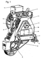
- Fig. 1 shows the ready assembled drive unit, consisting essentially of a motor 1, serving as a bearing plate motor stand 2, serving as a bearing plate bearing block 5, a traction sheave 15 and a machine frame 7 with counter-roller carrier 9.
- a motor 1 serving as a bearing plate motor stand 2
- a traction sheave 15 and a machine frame 7 with counter-roller carrier 9.
- the stator of the electric motor 1 is screwed by means of a flange to the motor stand 2.
- the rotor of the electric motor 1 is seated on a free end of a shaft carrying the traction sheave 15, which is mounted on the bearing block 5 and the motor stator 2.
- the free end of the shaft projects beyond the motor stand 2.
- the traction sheave 15, which is visible through an outbreak in a cable protection shuttering 3, is mounted on the motor stand 2 and on the bearing block 5 by means of the shaft.
- a brake 6 is arranged in the inner region of the motor stator 2 and covered with the shuttering 3. Depending on the structure of the drive unit, the brake 6 can also be arranged in the inner region of the bearing block 5.
- the motor stand 2 and the bearing block 5 are arranged on the machine frame 7, which has an adjustable support element 8 at its corners.
- the counter-roller carrier 9 is arranged on the underside of the machine frame 7. All electrical connections of the drive unit are located in a terminal box 10.
- the traction sheave 15 is accessible after opening a sliding cover 47 from the outside.
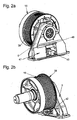
- Fig. 2a to 4b The structural design of the emergency drive is in the Fig. 2a to 4b explained in more detail, wherein in Fig. 2a and 2b an assembled and in Fig. 4a and 4b an exploded view of the assembly can be seen.
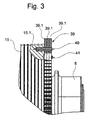
- Fig. 3 shows details of a arranged on the traction sheave 15 sprocket 39 and Fig. 5a and 5b an auxiliary device for the emergency drive.
- the sprocket 39 is constructed of toothed segments 39.1, which sit by means of clamping pins 40 which are hammered through the holes 39.2 and in the corresponding holes 15.1 in the traction sheave 15.
- the screws 41 which are inserted through the ring gear 39 and screwed into the traction sheave 15, hold the segments 39.1 together in the axial direction.
- a segment 39.1 is made up of layered, toothed sheet metal segments which can be produced inexpensively by means of stamping or cutting processes.
- the sprocket 39 is composed of a plurality of mutually offset in the circumferential direction layers of toothed segments 39.1, each segment 39.1 have at least two holes 39.2 for the pressed in the holes 15.1 of the traction sheave 15 dowels 40.
- the ring gear 39 is driven by means of a pinion 42 mounted on the shaft of a hydraulic motor 43.
- the motor 43 is used for this purpose in a receiving bore 5.1 of the bearing block 5 and secured with screws.
- the receiving bore 5.1 is located in the area covered by a cover 45.
- a mains-powered or battery-powered electric motor can be provided.
- a motor-driven toothed belt which transmits the motor power to a toothed ring provided instead of the toothed ring gear 39, the toothed belt wheel as the ring gear 39 is disposed on the circumference of the traction sheave 15.
- the end cap 45 has an opening 45.1, which is closable with a guided in the guides 45.2, 48 and 49 sliding cover 47.
- the sliding cover 47 Before the introduction of the hydraulic motor 43, the sliding cover 47 must be brought into the open position.
- a safety switch 50 the plunger 50.1 projecting through the hole 45.3 in the end cover 45, pushed back by the actuation curve 47.1, wherein a safety circuit is interrupted, so that the operation of the electric motor 1 during emergency operation is not possible.
- Fig. 5a and Fig. 5b show a mobile hydraulic unit, which consists of a carriage 51 with a support 51.1 for the hydraulic motor 43, a support 51.2 for receiving a hydraulic unit 52, wheels 51.3, a bracket 51.4 for placing the hydraulic hoses and two other brackets 51.5 for rolling up the electric cable for the power supply a pump motor 53 is made.
- the hydraulic unit 52 consists of a pump with pump motor 53, which can be turned on via a motor switch 54 and a directional control valve 55 for the control of the hydraulic motor 43. Further elements of the hydraulic unit 52 are an adjustable pressure relief valve 56 and an oil filter 57. In engine rooms without emergency power supply can instead of the pump motor 53, a hand pump with hydraulic accumulator may be provided.
Landscapes
- Cage And Drive Apparatuses For Elevators (AREA)
Claims (2)
- Entraînement de secours pour un ascenseur comprenant une unité d'entraînement qui déplace une cabine d'ascenseur et un contrepoids et qui se compose d'un moteur et d'une poulie motrice sur laquelle passent des câbles reliés à la cabine et au contrepoids, étant précisé que lors d'un fonctionnement de secours, ledit entraînement de secours agit sur l'unité d'entraînement, et qu'il est directement relié à la poulie motrice (15) et entraîne celle-ci, et qu'il est prévu sur la poulie motrice (15) une couronne dentée (39) qui est relié à un pignon (42) du moteur d'entraînement de secours (43),
caractérisé en ce que la couronne dentée (39) se compose de plusieurs couches de segments dentés (39.1) qui sont décalées les unes par rapport aux autres dans le sens circonférentiel, chaque segment (39.1) étant formé de segments dentés en tôle qui sont empilés. - Entraînement de secours selon la revendication 1, caractérisé en ce que chaque segment (39.1) présente au moins deux trous (39.2) pour recevoir des goupilles de serrage (40) enfoncées dans des trous (15.1) de la poulie motrice (15).
Priority Applications (1)
| Application Number | Priority Date | Filing Date | Title |
|---|---|---|---|
| EP20030002870 EP1338545B1 (fr) | 2002-02-18 | 2003-02-08 | Entraînement de secours pour ascenseur |
Applications Claiming Priority (3)
| Application Number | Priority Date | Filing Date | Title |
|---|---|---|---|
| EP02405122 | 2002-02-18 | ||
| EP02405122 | 2002-02-18 | ||
| EP20030002870 EP1338545B1 (fr) | 2002-02-18 | 2003-02-08 | Entraînement de secours pour ascenseur |
Publications (2)
| Publication Number | Publication Date |
|---|---|
| EP1338545A1 EP1338545A1 (fr) | 2003-08-27 |
| EP1338545B1 true EP1338545B1 (fr) | 2008-10-01 |
Family
ID=27665009
Family Applications (1)
| Application Number | Title | Priority Date | Filing Date |
|---|---|---|---|
| EP20030002870 Expired - Lifetime EP1338545B1 (fr) | 2002-02-18 | 2003-02-08 | Entraînement de secours pour ascenseur |
Country Status (1)
| Country | Link |
|---|---|
| EP (1) | EP1338545B1 (fr) |
Family Cites Families (3)
| Publication number | Priority date | Publication date | Assignee | Title |
|---|---|---|---|---|
| FR2129891B3 (fr) * | 1971-03-19 | 1973-12-28 | Pointu Jean | |
| FI98724C (fi) * | 1995-03-24 | 1997-08-11 | Kone Oy | Hissikoneiston hätäkäyttölaite |
| DE19725068C2 (de) * | 1997-06-12 | 2001-07-05 | Kone Corp | Rolltreppen- oder Rollsteigantrieb |
-
2003
- 2003-02-08 EP EP20030002870 patent/EP1338545B1/fr not_active Expired - Lifetime
Also Published As
| Publication number | Publication date |
|---|---|
| EP1338545A1 (fr) | 2003-08-27 |
Similar Documents
| Publication | Publication Date | Title |
|---|---|---|
| DE69403684T3 (de) | Aufzugsmotor im Gegengewicht eingesetzt | |
| DE69909133T2 (de) | Aufzugsantrieb mit gegenläufigen rotoren | |
| DE19952736A1 (de) | Antrieb, insbesondere für ein Hebezeug | |
| EP0563583A1 (fr) | Commande à moteur,en particulier commande à moteur électrique pour fenêtre ou toit-ouvrant | |
| EP2754826B1 (fr) | Unité d'entraînement pour une porte à tambour plate en forme de disque | |
| EP0999081A2 (fr) | Unité d'entraínement pour véhicule avec entraínement électrique | |
| DE10297270B4 (de) | Kompakter Antrieb für Aufzugtüren | |
| EP0440861B1 (fr) | Unité d'entraînement par rouleau | |
| EP0452261A1 (fr) | Groupe mobile générateur de pression hydraulique | |
| DE2541397C3 (de) | Antriebseinheit fur Rolltreppen | |
| DE69630066T2 (de) | Notantriebseinheit für eine Aufzugsmaschine | |
| AT507470A1 (de) | Antriebsvorrichtung für den druckbalken einer biegepresse | |
| EP1069068B1 (fr) | Entraînement compact pour un ascenseur | |
| DE3118805C2 (de) | Linearantriebseinheit | |
| EP1338545A1 (fr) | Entraínement de secours pour ascenseur | |
| DE102004005430A1 (de) | Ölpumpe für Kraftfahrzeug-Automatgetriebe | |
| EP1338550B1 (fr) | Unité d'entraînement avec frein pour un ascenseur | |
| DE10136031B4 (de) | Direktantrieb für eine Personenförderanlage | |
| DE19721072A1 (de) | Tragbare Elektropreßvorrichtung | |
| EP1722461A1 (fr) | Entrainement éléctrique | |
| DE4025913A1 (de) | Lageranordnung fuer mit hoher drehzahl antreibbare wellen | |
| EP1627841B1 (fr) | Entraînement pour un ascenseur | |
| DE3826929C1 (en) | Staircase lift for wheelchairs | |
| DE906719C (de) | Anordnung der Kraftuebertragungsmittel bei Aussenlaeufermotoren | |
| DE9116261U1 (de) | Antriebsmechanismus |
Legal Events
| Date | Code | Title | Description |
|---|---|---|---|
| PUAI | Public reference made under article 153(3) epc to a published international application that has entered the european phase |
Free format text: ORIGINAL CODE: 0009012 |
|
| AK | Designated contracting states |
Designated state(s): AT BE BG CH CY CZ DE DK EE ES FI FR GB GR HU IE IT LI LU MC NL PT SE SI SK TR |
|
| AX | Request for extension of the european patent |
Extension state: AL LT LV MK RO |
|
| 17P | Request for examination filed |
Effective date: 20040212 |
|
| AKX | Designation fees paid |
Designated state(s): AT CH DE FR GB LI |
|
| GRAP | Despatch of communication of intention to grant a patent |
Free format text: ORIGINAL CODE: EPIDOSNIGR1 |
|
| GRAS | Grant fee paid |
Free format text: ORIGINAL CODE: EPIDOSNIGR3 |
|
| GRAA | (expected) grant |
Free format text: ORIGINAL CODE: 0009210 |
|
| AK | Designated contracting states |
Kind code of ref document: B1 Designated state(s): AT CH DE FR GB LI |
|
| REG | Reference to a national code |
Ref country code: GB Ref legal event code: FG4D Free format text: NOT ENGLISH |
|
| REG | Reference to a national code |
Ref country code: CH Ref legal event code: EP |
|
| REF | Corresponds to: |
Ref document number: 50310558 Country of ref document: DE Date of ref document: 20081113 Kind code of ref document: P |
|
| REG | Reference to a national code |
Ref country code: HK Ref legal event code: GR Ref document number: 1058181 Country of ref document: HK |
|
| PLBE | No opposition filed within time limit |
Free format text: ORIGINAL CODE: 0009261 |
|
| STAA | Information on the status of an ep patent application or granted ep patent |
Free format text: STATUS: NO OPPOSITION FILED WITHIN TIME LIMIT |
|
| 26N | No opposition filed |
Effective date: 20090702 |
|
| PGFP | Annual fee paid to national office [announced via postgrant information from national office to epo] |
Ref country code: AT Payment date: 20100212 Year of fee payment: 8 |
|
| PG25 | Lapsed in a contracting state [announced via postgrant information from national office to epo] |
Ref country code: AT Free format text: LAPSE BECAUSE OF NON-PAYMENT OF DUE FEES Effective date: 20110208 |
|
| REG | Reference to a national code |
Ref country code: FR Ref legal event code: PLFP Year of fee payment: 14 |
|
| REG | Reference to a national code |
Ref country code: FR Ref legal event code: PLFP Year of fee payment: 15 |
|
| REG | Reference to a national code |
Ref country code: FR Ref legal event code: PLFP Year of fee payment: 16 |
|
| PGFP | Annual fee paid to national office [announced via postgrant information from national office to epo] |
Ref country code: GB Payment date: 20220222 Year of fee payment: 20 Ref country code: DE Payment date: 20220225 Year of fee payment: 20 Ref country code: CH Payment date: 20220218 Year of fee payment: 20 |
|
| PGFP | Annual fee paid to national office [announced via postgrant information from national office to epo] |
Ref country code: FR Payment date: 20220224 Year of fee payment: 20 |
|
| REG | Reference to a national code |
Ref country code: DE Ref legal event code: R071 Ref document number: 50310558 Country of ref document: DE |
|
| REG | Reference to a national code |
Ref country code: CH Ref legal event code: PL |
|
| REG | Reference to a national code |
Ref country code: GB Ref legal event code: PE20 Expiry date: 20230207 |
|
| PG25 | Lapsed in a contracting state [announced via postgrant information from national office to epo] |
Ref country code: GB Free format text: LAPSE BECAUSE OF EXPIRATION OF PROTECTION Effective date: 20230207 |