EP1338545B1 - Notantrieb für einen Aufzug - Google Patents
Notantrieb für einen Aufzug Download PDFInfo
- Publication number
- EP1338545B1 EP1338545B1 EP20030002870 EP03002870A EP1338545B1 EP 1338545 B1 EP1338545 B1 EP 1338545B1 EP 20030002870 EP20030002870 EP 20030002870 EP 03002870 A EP03002870 A EP 03002870A EP 1338545 B1 EP1338545 B1 EP 1338545B1
- Authority
- EP
- European Patent Office
- Prior art keywords
- traction sheave
- motor
- drive
- emergency
- emergency drive
- Prior art date
- Legal status (The legal status is an assumption and is not a legal conclusion. Google has not performed a legal analysis and makes no representation as to the accuracy of the status listed.)
- Expired - Lifetime
Links
- 238000005520 cutting process Methods 0.000 description 2
- 238000004519 manufacturing process Methods 0.000 description 2
- 239000002184 metal Substances 0.000 description 2
- 238000009416 shuttering Methods 0.000 description 2
- 238000004891 communication Methods 0.000 description 1
- 230000008878 coupling Effects 0.000 description 1
- 238000010168 coupling process Methods 0.000 description 1
- 238000005859 coupling reaction Methods 0.000 description 1
- 238000005096 rolling process Methods 0.000 description 1
- 238000003860 storage Methods 0.000 description 1
Images


Classifications
-
- B—PERFORMING OPERATIONS; TRANSPORTING
- B66—HOISTING; LIFTING; HAULING
- B66B—ELEVATORS; ESCALATORS OR MOVING WALKWAYS
- B66B5/00—Applications of checking, fault-correcting, or safety devices in elevators
- B66B5/02—Applications of checking, fault-correcting, or safety devices in elevators responsive to abnormal operating conditions
- B66B5/027—Applications of checking, fault-correcting, or safety devices in elevators responsive to abnormal operating conditions to permit passengers to leave an elevator car in case of failure, e.g. moving the car to a reference floor or unlocking the door
Definitions
- the invention relates to an emergency drive for an elevator with an elevator car and a counterweight moving drive unit consisting of motor and traction sheave, are connected to the elevator car and the counterweight connected ropes, wherein in emergency operation of the emergency drive acts on the drive unit and the traction sheave on the periphery drives and on the traction sheave a sprocket is provided which is in communication with a pinion of an engine of the emergency drive.
- a reciprocating motor fed with alternating voltage consists essentially of a stator and of a rotor with a rotor hub which can be pushed onto the main shaft. At the drive end of the main shaft creates a second clamping set a firm connection between the Main shaft and rotor hub.
- a manual drive with a worm gear acting on the main shaft enables a manual movement of the main shaft in the event of a power failure.
- a disadvantage of the known device is that a great effort to move the main shaft is necessary.
- such emergency drives are very expensive.
- an elevator drive consisting of a disc motor with integrated traction sheave and outer shoe brake has become known.
- a sprocket On the inside of a brake drum, a sprocket is provided, in which a pinion of an emergency drive acts during emergency operation.
- the rotor of the motor is disk-shaped, wherein the traction sheave on the rotor and the brake drum are arranged on the circumference of the rotor.
- a disadvantage of this emergency drive is the production of complex and expensive, disc-shaped rotor with traction sheave and brake drum with internal sprocket.
- the invention aims to remedy this situation.
- the invention as characterized in claim 1 solves the problem of avoiding the disadvantages of the known device and to propose a simply built emergency drive.
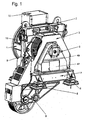
- Fig. 1 shows the ready assembled drive unit, consisting essentially of a motor 1, serving as a bearing plate motor stand 2, serving as a bearing plate bearing block 5, a traction sheave 15 and a machine frame 7 with counter-roller carrier 9.
- a motor 1 serving as a bearing plate motor stand 2
- a traction sheave 15 and a machine frame 7 with counter-roller carrier 9.
- the stator of the electric motor 1 is screwed by means of a flange to the motor stand 2.
- the rotor of the electric motor 1 is seated on a free end of a shaft carrying the traction sheave 15, which is mounted on the bearing block 5 and the motor stator 2.
- the free end of the shaft projects beyond the motor stand 2.
- the traction sheave 15, which is visible through an outbreak in a cable protection shuttering 3, is mounted on the motor stand 2 and on the bearing block 5 by means of the shaft.
- a brake 6 is arranged in the inner region of the motor stator 2 and covered with the shuttering 3. Depending on the structure of the drive unit, the brake 6 can also be arranged in the inner region of the bearing block 5.
- the motor stand 2 and the bearing block 5 are arranged on the machine frame 7, which has an adjustable support element 8 at its corners.
- the counter-roller carrier 9 is arranged on the underside of the machine frame 7. All electrical connections of the drive unit are located in a terminal box 10.
- the traction sheave 15 is accessible after opening a sliding cover 47 from the outside.
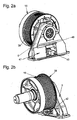
- Fig. 2a to 4b The structural design of the emergency drive is in the Fig. 2a to 4b explained in more detail, wherein in Fig. 2a and 2b an assembled and in Fig. 4a and 4b an exploded view of the assembly can be seen.
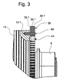
- Fig. 3 shows details of a arranged on the traction sheave 15 sprocket 39 and Fig. 5a and 5b an auxiliary device for the emergency drive.
- the sprocket 39 is constructed of toothed segments 39.1, which sit by means of clamping pins 40 which are hammered through the holes 39.2 and in the corresponding holes 15.1 in the traction sheave 15.
- the screws 41 which are inserted through the ring gear 39 and screwed into the traction sheave 15, hold the segments 39.1 together in the axial direction.
- a segment 39.1 is made up of layered, toothed sheet metal segments which can be produced inexpensively by means of stamping or cutting processes.
- the sprocket 39 is composed of a plurality of mutually offset in the circumferential direction layers of toothed segments 39.1, each segment 39.1 have at least two holes 39.2 for the pressed in the holes 15.1 of the traction sheave 15 dowels 40.
- the ring gear 39 is driven by means of a pinion 42 mounted on the shaft of a hydraulic motor 43.
- the motor 43 is used for this purpose in a receiving bore 5.1 of the bearing block 5 and secured with screws.
- the receiving bore 5.1 is located in the area covered by a cover 45.
- a mains-powered or battery-powered electric motor can be provided.
- a motor-driven toothed belt which transmits the motor power to a toothed ring provided instead of the toothed ring gear 39, the toothed belt wheel as the ring gear 39 is disposed on the circumference of the traction sheave 15.
- the end cap 45 has an opening 45.1, which is closable with a guided in the guides 45.2, 48 and 49 sliding cover 47.
- the sliding cover 47 Before the introduction of the hydraulic motor 43, the sliding cover 47 must be brought into the open position.
- a safety switch 50 the plunger 50.1 projecting through the hole 45.3 in the end cover 45, pushed back by the actuation curve 47.1, wherein a safety circuit is interrupted, so that the operation of the electric motor 1 during emergency operation is not possible.
- Fig. 5a and Fig. 5b show a mobile hydraulic unit, which consists of a carriage 51 with a support 51.1 for the hydraulic motor 43, a support 51.2 for receiving a hydraulic unit 52, wheels 51.3, a bracket 51.4 for placing the hydraulic hoses and two other brackets 51.5 for rolling up the electric cable for the power supply a pump motor 53 is made.
- the hydraulic unit 52 consists of a pump with pump motor 53, which can be turned on via a motor switch 54 and a directional control valve 55 for the control of the hydraulic motor 43. Further elements of the hydraulic unit 52 are an adjustable pressure relief valve 56 and an oil filter 57. In engine rooms without emergency power supply can instead of the pump motor 53, a hand pump with hydraulic accumulator may be provided.
Landscapes
- Cage And Drive Apparatuses For Elevators (AREA)
Description
- Die Erfindung betrifft einen Notantrieb für einen Aufzug mit einer eine Aufzugskabine und ein Gegengewicht bewegende Antriebseinheit bestehend aus Motor und Treibscheibe, über die mit der Aufzugskabine und dem Gegengewicht verbundene Seile geführt sind, wobei bei Notbetrieb der Notantrieb auf die Antriebseinheit einwirkt und die Treibscheibe am Umfang antreibt und an der Treibscheibe ein Zahnkranz vorgesehen ist, der in Verbindung steht mit einem Ritzel eines Motors des Notantriebes.
- Aus der
Patentschrift EP 0 468 168 B1 ist eine getriebelose Antriebsmaschine für Aufzüge bekannt geworden, bei der ein Maschinenrahmen einen Lagerbock und einen Schildbock trägt. Eine Hauptwelle ist mittels eines am Lagerbock angeordneten Loslagers und mittels eines am Schildbock angeordneten Festlagers abtriebsseitig an zwei Stellen gelagert. Zwischen den Lagerstellen ist eine Treibscheibe mit Bremsscheibe vorgesehen. Die Treibscheibe steht mittels eines ersten Spannsatzes in fester Verbindung mit der Hauptwelle. Die beidseitige Lagerung der Treibscheibe erlaubt bei kleinen Deformationen der Hauptwelle grosse Radiallasten. Ein mit Wechselspannung gespeister Hubmotor besteht im wesentlichen aus einem Stator und aus einem Rotor mit einer auf die Hauptwelle aufschiebbaren Rotornabe. Am antriebsseitigen Ende der Hauptwelle schafft ein zweiter Spannsatz eine feste Verbindung zwischen der Hauptwelle und der Rotornabe. Am den Lagerbock und den Schildbock tragenden Maschinenrahmen ist auch ein Gegenrollenträger mit einer Gegenrolle angeordnet, die dazu dient, den durch die Abmessungen der Aufzugskabine und des Gegengewichtes sowie der Seilführung vorgegebenen Seilstrangabstand einzuhalten. Ein auf die Hauptwelle wirkender Handantrieb mit einem Schneckengetriebe ermöglicht bei Spannungsausfall ein manuelles Bewegen der Hauptwelle. - Ein Nachteil der bekannten Einrichtung liegt darin, dass ein grosser Kraftaufwand zum Bewegen der Hauptwelle notwendig ist. Ausserdem sind derartige Notantriebe sehr teuer.
- Aus der
EP 0 733 577 A2 ist ein Aufzugsantrieb bestehend aus einem Scheibenmotor mit integrierter Treibscheibe und Aussenbackenbremse bekannt geworden. An der Innenseite einer Bremstrommel ist ein Zahnkranz vorgesehen, in den ein Ritzel eines Notantriebes bei Notbetrieb einwirkt. Der Rotor des Motors ist scheibenförmig ausgebildet, wobei die Treibscheibe am Rotor und die Bremstrommel am Umfang des Rotors angeordnet sind. - Nachteilig bei diesem Notantrieb ist die Herstellung des komplexen und kostenintensiven, scheibenförmigen Rotors mit Treibscheibe und Bremstrommel mit innenliegendem Zahnkranz.
- Hier will die Erfindung Abhilfe schaffen. Die Erfindung, wie sie in Anspruch 1 gekennzeichnet ist, löst die Aufgabe, die Nachteile der bekannten Einrichtung zu vermeiden und einen einfach gebauten Notantrieb vorzuschlagen.
- Die durch die Erfindung erreichten Vorteile sind im wesentlichen darin zu sehen, dass die bisher je Antriebseinheit verwendeten schweren und teuren Getriebe durch einen kompakten Antrieb ersetzt werden, der je Maschinenraum lediglich einmal vorhanden sein muss. Der Antrieb wird nur bei der sich im Notbetrieb befindenden Antriebseinheit eingesetzt. Nach dem Notbetrieb wird der Antrieb wieder von der Antriebseinheit entfernt. Weiter vorteilhaft ist die kostengünstige Herstellung des an der Treibscheibe angeordneten Zahnkranzes, wobei die Zahnsegmente aus geschichteten, verzahnten Blechsegmenten aufgebaut sind, die mittels Stanz- oder Schneidverfahren billig herstellbar sind.
- Anhand der beiliegenden Figuren wird die vorliegende Erfindung näher erläutert.
- Es zeigen:
-
Fig. 1
eine Antriebseinheit mit Treibscheibe, -
Fig. 2a und 2b
die Treibscheibe mit einem Zahnkranz, -
Fig. 3
Einzelheiten des Zahnkranzes, -
Fig. 4a und 4b
eine explodierte Darstellung derFig. 2a und 2b und -
Fig. 5a und 5b
eine Hilfseinrichtung für den Notantrieb. -
Fig. 1 zeigt die fertig zusammengebaute Antriebseinheit, im wesentlichen bestehend aus einem Motor 1, einem als Lagerschild dienender Motorständer 2, einem als Lagerschild dienender Lagerbock 5, einer Treibscheibe 15 und einem Maschinenrahmen 7 mit Gegenrollenträger 9. Über die Treibscheibe 15 sind nicht dargestellte Seile geführt, die einenends mit einer Aufzugskabine verbunden sind und die anderenends mit einem Gegengewicht verbunden sind. Der Stator des Elektromotors 1 ist mittels eines Flansches mit dem Motorständer 2 verschraubt. Der Rotor des Elektromotors 1 sitzt auf einem freien Ende einer die Treibscheibe 15 tragenden Welle, die am Lagerbock 5 und am Motorständer 2 gelagert ist. Das freie Wellenende überragt den Motorständer 2. Die durch einen Ausbruch in einer Seilschutzverschalung 3 sichtbare Treibscheibe 15 ist mittels der Welle am Motorständer 2 und am Lagerbock 5 gelagert. Eine Bremse 6 ist im inneren Bereich des Motorständers 2 angeordnet und mit der Verschalung 3 abgedeckt. Je nach Aufbau der Antriebseinheit kann die Bremse 6 auch im inneren Bereich des Lagerbockes 5 angeordnet sein. - Der Motorständer 2 und der Lagerbock 5 sind am Maschinenrahmen 7 angeordnet, welcher an seinen Ecken je ein einstellbares Stützelement 8 aufweist. Der Gegenrollenträger 9 ist an der Unterseite des Maschinenrahmens 7 angeordnet. Alle elektrischen Anschlüsse der Antriebseinheit befinden sich in einem Klemmenkasten 10. Die Treibscheibe 15 ist nach dem Öffnen eines Schiebedeckels 47 von aussen zugänglich.
- Der konstruktive Aufbau des Notantriebes ist in den
Fig. 2a bis 4b näher erläutert, wobei inFig. 2a und 2b eine zusammengebaute und inFig. 4a und 4b eine explodierte Darstellung der Baugruppe zu sehen ist.Fig. 3 zeigt Einzelheiten eines an der Treibscheibe 15 angeordneten Zahnkranzes 39 undFig. 5a und 5b eine Hilfseinrichtung für den Notantrieb. - Im Notbetrieb wird die Treibscheibe 15 über den Zahnkranz 39 angetrieben. Der Zahnkranz 39 ist aus verzahnten Segmenten 39.1 aufgebaut, welche mittels Spannstiften 40, die durch die Löcher 39.2 eingeschlagen sind und in den entsprechenden Bohrungen 15.1 in der Treibscheibe 15 sitzen. Die Schrauben 41, die durch den Zahnkranz 39 durchgesteckt und in die Treibscheibe 15 eingeschraubt sind, halten die Segmente 39.1 in axialer Richtung zusammen. Ein Segment 39.1 ist aus geschichteten, verzahnten Blechsegmenten aufgebaut, die mittels Stanzoder Schneidverfahren billig herstellbar sind. Der Zahnkranz 39 ist aus mehreren, gegenseitig in der Umfangsrichtung versetzten Schichten von verzahnten Segmenten 39.1 aufgebaut, wobei jedes Segment 39.1 mindestens zwei Löcher 39.2 für die in den Löchern 15.1 der Treibscheibe 15 eingepressten Spannstiften 40 aufweisen.
- Der Zahnkranz 39 wird mittels eines auf der Welle eines Hydraulikmotors 43 montierten Ritzels 42 angetrieben. Der Motor 43 wird zu diesem Zweck in eine Aufnahmebohrung 5.1 des Lagerbockes 5 eingesetzt und mit Schrauben befestigt. Die Aufnahmebohrung 5.1 befindet sich im Bereich, der mit einem Abschlussdeckel 45 abgedeckt ist. Anstelle des Hydraulikmotors 43 kann beispielsweise ein netzgespeister oder batteriegespeister Elektromotor vorgesehen sein. Anstelle der direkten Zahnkopplung zwischen dem Zahnkranz 39 und dem Ritzel 42 kann beispielsweise ein motorisch angetriebener Zahnriemen vorgesehen sein, der die Motorkraft auf ein anstelle des Zahnkranzes 39 vorgesehenes Zahnriemenrad überträgt, wobei das Zahnriemenrad wie der Zahnkranz 39 am Umfang der Treibscheibe 15 angeordnet ist.
- Der Abschlussdeckel 45 hat eine Öffnung 45.1, welche mit einem in den Führungen 45.2, 48 und 49 geführten Schiebedeckel 47 verschliessbar ist. Vor der Einführung des Hydraulikmotors 43 muss der Schiebedeckel 47 in die offene Stellung gebracht werden. Dabei wird ein Sicherheitsschalter 50, dessen Stössel 50.1 durch das Loch 45.3 im Abschlussdeckel 45 vorsteht, durch die Betätigungskurve 47.1 zurückgedrückt, wobei ein Sicherheitskreis unterbrochen wird, so dass der Betrieb des Elektromotors 1 während des Notbetriebs nicht möglich ist.
-
Fig. 5a und Fig. 5b zeigen ein fahrbares Hydraulikaggregat, welches aus einem Wagen 51 mit einem Träger 51.1 für den Hydraulikmotor 43, einem Träger 51.2 zur Aufnahme eines Hydraulikaggregats 52, Räder 51.3, eines Bügels 51.4 zur Plazierung der Hydraulikschläuche sowie zwei weiteren Bügeln 51.5 zum Aufrollen des Elektrokabels für die Speisung eines Pumpenmotors 53 besteht. - Das Hydraulikaggregat 52 besteht aus einer Pumpe mit Pumpenmotor 53, der über einen Motorschalter 54 eingeschaltet werden kann sowie ein Wegeventil 55 für die Steuerung des Hydraulikmotors 43. Weitere Elemente des Hydraulikaggregates 52 sind ein einstellbares Überdruckventil 56 und ein Ölfilter 57. In Maschinenräumen ohne Notstromversorgung kann anstelle des Pumpenmotors 53 eine Handpumpe mit Hydraulikspeicher vorgesehen sein.
Claims (2)
- Notantrieb für einen Aufzug mit einer eine Aufzugskabine und ein Gegengewicht bewegende Antriebseinheit bestehend aus Motor und Treibscheibe, über die mit der Aufzugskabine und dem Gegengewicht verbundene Seile geführt sind, wobei bei Notbetrieb der Notantrieb auf die Antriebseinheit einwirkt,
und der Notantrieb direkt mit der Treibscheibe (15) verbunden ist und diese antreibt,
und wobei an der Treibscheibe (15) ein Zahnkranz (39) vorgesehen ist, der in Verbindung steht mit einem Ritzel (42) des Notantriebsmotors (43),
dadurch gekennzeichnet,
dass der Zahnkranz (39) aus mehreren, gegenseitig in der Umfangsrichtung versetzten Schichten von verzahnten Segmenten (39.1) gebildet ist, wobei jedes Segment (39.1) aus geschichteten, verzahnten Blechsegmenten aufgebaut ist. - Notantrieb nach Anspruch 1,
dadurch gekennzeichnet,
dass jedes Segment (39.1) mindestens zwei Löcher (39.2) für die Aufnahme von in Löchern (15.1) der Treibscheibe (15) eingepressten Spannstiften (40) aufweist.
Priority Applications (1)
| Application Number | Priority Date | Filing Date | Title |
|---|---|---|---|
| EP20030002870 EP1338545B1 (de) | 2002-02-18 | 2003-02-08 | Notantrieb für einen Aufzug |
Applications Claiming Priority (3)
| Application Number | Priority Date | Filing Date | Title |
|---|---|---|---|
| EP02405122 | 2002-02-18 | ||
| EP02405122 | 2002-02-18 | ||
| EP20030002870 EP1338545B1 (de) | 2002-02-18 | 2003-02-08 | Notantrieb für einen Aufzug |
Publications (2)
| Publication Number | Publication Date |
|---|---|
| EP1338545A1 EP1338545A1 (de) | 2003-08-27 |
| EP1338545B1 true EP1338545B1 (de) | 2008-10-01 |
Family
ID=27665009
Family Applications (1)
| Application Number | Title | Priority Date | Filing Date |
|---|---|---|---|
| EP20030002870 Expired - Lifetime EP1338545B1 (de) | 2002-02-18 | 2003-02-08 | Notantrieb für einen Aufzug |
Country Status (1)
| Country | Link |
|---|---|
| EP (1) | EP1338545B1 (de) |
Family Cites Families (3)
| Publication number | Priority date | Publication date | Assignee | Title |
|---|---|---|---|---|
| FR2129891B3 (de) * | 1971-03-19 | 1973-12-28 | Pointu Jean | |
| FI98724C (fi) * | 1995-03-24 | 1997-08-11 | Kone Oy | Hissikoneiston hätäkäyttölaite |
| DE19725068C2 (de) * | 1997-06-12 | 2001-07-05 | Kone Corp | Rolltreppen- oder Rollsteigantrieb |
-
2003
- 2003-02-08 EP EP20030002870 patent/EP1338545B1/de not_active Expired - Lifetime
Also Published As
| Publication number | Publication date |
|---|---|
| EP1338545A1 (de) | 2003-08-27 |
Similar Documents
| Publication | Publication Date | Title |
|---|---|---|
| DE69403684T3 (de) | Aufzugsmotor im Gegengewicht eingesetzt | |
| DE69909133T2 (de) | Aufzugsantrieb mit gegenläufigen rotoren | |
| DE19952736A1 (de) | Antrieb, insbesondere für ein Hebezeug | |
| EP0563583A1 (de) | Motorantrieb,insbesondere elektromotorischer Fenster- oder Schiebedachantrieb | |
| EP2754826B1 (de) | Antriebseinheit für eine Karusselltür in einer flachen, scheibenförmigen Bauform | |
| EP0999081A2 (de) | Antriebseinheit für ein elektrisch angetriebenes Fahrzeug | |
| DE10297270B4 (de) | Kompakter Antrieb für Aufzugtüren | |
| EP0440861B1 (de) | Antriebsrolleneinheit | |
| EP0452261A1 (de) | Fahrbares, hydraulisches Antriebsaggregat | |
| DE2541397C3 (de) | Antriebseinheit fur Rolltreppen | |
| AT507470B1 (de) | Antriebsvorrichtung für den druckbalken einer biegepresse | |
| DE3115845A1 (de) | Toepferscheibe mit elektrischem antrieb | |
| EP1338545B1 (de) | Notantrieb für einen Aufzug | |
| DE3118805C2 (de) | Linearantriebseinheit | |
| EP1338550B1 (de) | Antriebseinheit mit Bremse für einen Aufzug | |
| DE112023006063T5 (de) | Doppelzweckschiebewagen | |
| DE10136031B4 (de) | Direktantrieb für eine Personenförderanlage | |
| DE19721072A1 (de) | Tragbare Elektropreßvorrichtung | |
| EP1722461A1 (de) | Elektrische Antriebsvorrichtung | |
| EP1627841B1 (de) | Antrieb für eine Aufzugsanlage | |
| DE3826929C1 (en) | Staircase lift for wheelchairs | |
| DE906719C (de) | Anordnung der Kraftuebertragungsmittel bei Aussenlaeufermotoren | |
| DE9116261U1 (de) | Antriebsmechanismus | |
| EP1550630B1 (de) | Aufzug-Elektromotor | |
| DE1911195U (de) | Antrieb der seiltrommerl von hebezeugen. |
Legal Events
| Date | Code | Title | Description |
|---|---|---|---|
| PUAI | Public reference made under article 153(3) epc to a published international application that has entered the european phase |
Free format text: ORIGINAL CODE: 0009012 |
|
| AK | Designated contracting states |
Designated state(s): AT BE BG CH CY CZ DE DK EE ES FI FR GB GR HU IE IT LI LU MC NL PT SE SI SK TR |
|
| AX | Request for extension of the european patent |
Extension state: AL LT LV MK RO |
|
| 17P | Request for examination filed |
Effective date: 20040212 |
|
| AKX | Designation fees paid |
Designated state(s): AT CH DE FR GB LI |
|
| GRAP | Despatch of communication of intention to grant a patent |
Free format text: ORIGINAL CODE: EPIDOSNIGR1 |
|
| GRAS | Grant fee paid |
Free format text: ORIGINAL CODE: EPIDOSNIGR3 |
|
| GRAA | (expected) grant |
Free format text: ORIGINAL CODE: 0009210 |
|
| AK | Designated contracting states |
Kind code of ref document: B1 Designated state(s): AT CH DE FR GB LI |
|
| REG | Reference to a national code |
Ref country code: GB Ref legal event code: FG4D Free format text: NOT ENGLISH |
|
| REG | Reference to a national code |
Ref country code: CH Ref legal event code: EP |
|
| REF | Corresponds to: |
Ref document number: 50310558 Country of ref document: DE Date of ref document: 20081113 Kind code of ref document: P |
|
| REG | Reference to a national code |
Ref country code: HK Ref legal event code: GR Ref document number: 1058181 Country of ref document: HK |
|
| PLBE | No opposition filed within time limit |
Free format text: ORIGINAL CODE: 0009261 |
|
| STAA | Information on the status of an ep patent application or granted ep patent |
Free format text: STATUS: NO OPPOSITION FILED WITHIN TIME LIMIT |
|
| 26N | No opposition filed |
Effective date: 20090702 |
|
| PGFP | Annual fee paid to national office [announced via postgrant information from national office to epo] |
Ref country code: AT Payment date: 20100212 Year of fee payment: 8 |
|
| PG25 | Lapsed in a contracting state [announced via postgrant information from national office to epo] |
Ref country code: AT Free format text: LAPSE BECAUSE OF NON-PAYMENT OF DUE FEES Effective date: 20110208 |
|
| REG | Reference to a national code |
Ref country code: FR Ref legal event code: PLFP Year of fee payment: 14 |
|
| REG | Reference to a national code |
Ref country code: FR Ref legal event code: PLFP Year of fee payment: 15 |
|
| REG | Reference to a national code |
Ref country code: FR Ref legal event code: PLFP Year of fee payment: 16 |
|
| PGFP | Annual fee paid to national office [announced via postgrant information from national office to epo] |
Ref country code: GB Payment date: 20220222 Year of fee payment: 20 Ref country code: DE Payment date: 20220225 Year of fee payment: 20 Ref country code: CH Payment date: 20220218 Year of fee payment: 20 |
|
| PGFP | Annual fee paid to national office [announced via postgrant information from national office to epo] |
Ref country code: FR Payment date: 20220224 Year of fee payment: 20 |
|
| REG | Reference to a national code |
Ref country code: DE Ref legal event code: R071 Ref document number: 50310558 Country of ref document: DE |
|
| REG | Reference to a national code |
Ref country code: CH Ref legal event code: PL |
|
| REG | Reference to a national code |
Ref country code: GB Ref legal event code: PE20 Expiry date: 20230207 |
|
| PG25 | Lapsed in a contracting state [announced via postgrant information from national office to epo] |
Ref country code: GB Free format text: LAPSE BECAUSE OF EXPIRATION OF PROTECTION Effective date: 20230207 |