EP1338547A2 - Module de porte - Google Patents
Module de porte Download PDFInfo
- Publication number
- EP1338547A2 EP1338547A2 EP03003898A EP03003898A EP1338547A2 EP 1338547 A2 EP1338547 A2 EP 1338547A2 EP 03003898 A EP03003898 A EP 03003898A EP 03003898 A EP03003898 A EP 03003898A EP 1338547 A2 EP1338547 A2 EP 1338547A2
- Authority
- EP
- European Patent Office
- Prior art keywords
- section
- door segment
- door
- cross
- main wall
- Prior art date
- Legal status (The legal status is an assumption and is not a legal conclusion. Google has not performed a legal analysis and makes no representation as to the accuracy of the status listed.)
- Withdrawn
Links
Images
Classifications
-
- B—PERFORMING OPERATIONS; TRANSPORTING
- B66—HOISTING; LIFTING; HAULING
- B66B—ELEVATORS; ESCALATORS OR MOVING WALKWAYS
- B66B13/00—Doors, gates, or other apparatus controlling access to, or exit from, cages or lift well landings
- B66B13/30—Constructional features of doors or gates
- B66B13/303—Details of door panels
Definitions
- the invention relates to a door segment, in particular an elevator door segment, with one essentially rectangular cross-section, that of two main wall sections and two side wall sections is formed.
- the object of the invention is therefore a door segment to create according to the preamble of claim 1, that is easy and inexpensive to manufacture.
- the task is solved by a door segment, the has the features of claim 1.
- the integrated snap elements can do both Parts of the door segment detachable or non-detachable with each other get connected. Composing the either part of a door segment can be done manually or done automatically. Because of the integrated Snap elements can on the use of welding robots to be dispensed with.
- a preferred embodiment of the door segment is characterized in that the two parts of the Door segment, viewed in cross section, essentially equally trained and assembled Condition rotated by 180 ° to each other are. Due to the same training in cross-section of the two parts of the door segment is its manufacture considerably simplified. From the 180 ° to each other twisted arrangement of the two parts of the Door segment results in a rectangular cross-section, which is hollow inside. Internally of the rectangular cross section can be a core be added to the door segment mechanically and / or to stabilize thermally.
- the core can for example, have a honeycomb structure.
- the core can also be made from a mineral wool fabric be formed.
- Another preferred embodiment of the Door segment is characterized in that, in Cross section considered, at one end of the Main wall section an outside wall section in particular angled by essentially 90 ° is, the free end of which is essentially around Is angled 90 ° to a holding section to form, which is essentially parallel to that Main wall section is arranged.
- the outside wall sections of the two parts of the door segment form the outside when assembled facing side wall surfaces of the door segment.
- the angled holding portion of part of the Door segment serves the other part of the door segment to position.
- the Holding sections of a door segment each with the Holding sections of other door segments engaged come to a complete from multiple door segments Door to form.
- Another preferred embodiment of the Door segment is characterized in that, in Cross section viewed at the other end of the Main wall section a support section in particular is angled by essentially 90 °, the free end in particular angled by 180 ° to form an inside wall portion. Due to the length of the bulkhead section the distance between the two main wall sections Door segments defined to each other. The inside wall section part of the door segment comes when assembled on the inside of the Outside wall section of the other part of the Door segment to the system. This creates a fixation the main wall sections reached in the longitudinal direction.
- Another preferred embodiment of the Door segment is characterized in that the Distance between the angled holding section and the main wall section, viewed in cross section, corresponds to the length of the inside wall section. This ensures that the two Main wall sections of a door segment in the assembled Condition to be fixed transversely to each other.
- Another preferred embodiment of the Door segment is characterized in that the free end of the inner wall section, in cross section considered, in particular angled by essentially 90 ° is to form a fixing section which is substantially parallel to the main wall section is arranged.
- the fixing section of the part of the door segment comes in the assembled Condition inside of the other's holding portion Part of the door segment to the system.
- Another preferred embodiment of the Door segment is characterized in that, in Cross-section viewed at the free end of the fixing section an inner snap element is formed is.
- the inner snap element serves the both parts of the door segment in the assembled Fix state relative to each other.
- Another preferred embodiment of the Door segment is characterized in that the inner snap element, viewed in cross section, formed at the free end of the fixing portion is angled to the associated main wall section is. This has the advantage that inner snap element, as well as the support section, the inside wall portion and the fixing portion by folding the main wall section can be generated.
- Another preferred embodiment of the Door segment is characterized in that, in Cross section viewed at the free end of the holding portion an outer snap element is formed is.
- the outer snap element of one part a door segment works when assembled together with the inner snap element, which on the other part of the door segment is formed.
- Another preferred embodiment of the Door segment is characterized in that the outer snap element, viewed in cross section, formed by the free end of the holding section becomes. This provides the advantage that the outside Snap element, as well as the outside wall section and the holding section by folding the Main wall section can be formed.
- the outer snap element viewed in cross section, starting from the holding section a rounded first section, a second section, which in Substantially parallel and spaced apart from the holding section is arranged, and a third section has, which is angled toward the holding portion is.
- the rounded first section allows a gliding past between the fixing section and inside wall portion Edge when assembling the door segment.
- the first Section of the outer snap element can take place the or in addition to the rounding also with a Bevelled bevels.
- the second section and form the angled third section a locking tab or snap hook. To the angled third section comes in the assembled Condition of the door segment the angled free end of the fixing section of the other part of the door segment to the system.
- Another preferred embodiment of the Door segment is characterized in that the third section of the outer snap element essentially parallel to the free end of the fixing section is arranged, the inner snap element forms. This will loosen the assembled Condition preferably against each other pre-tensioned snap elements prevented from each other.
- Another preferred embodiment of the Door segment is characterized in that the Holding section of a part of the door segment in the assembled condition of the two parts of the Main wall section of the other part spaced is. As a result, an angled, L-shaped profile formed by a complementary trained profile of another door segment can be attacked.
- Another preferred embodiment of the Door segment is characterized in that the two parts of the door segment each in one piece a foldable material, in particular sheet metal material, are formed.
- the configuration described above of the door segment enables production of the two parts of the door segment with the integrated Snap elements by bending. Bending is one the most common types of forming of sheets. That extends from the Mass production of small parts up to the production of individual parts in plant engineering. In most cases is cold formed, only in special cases large cross sections or very small bending radii, the material is heated to the for forming to reduce required forces respectively about higher shape changes with a given material to be able to achieve.
- Another preferred embodiment of the Door segment is characterized in that at least part of the door segment made of galvanized Sheet steel, stainless steel or aluminum is formed.
- the use of these materials provides the advantage that no additional treatment is required is to protect the parts from corrosion.
- Another preferred embodiment of the Door segment is characterized in that the two parts made of different materials are.
- the invisible parts of the door segment can for example made of galvanized sheet steel be educated, whereas the visible Parts can be made of stainless steel.
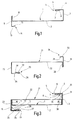
- Figure 1 is a first part 1 of an elongated Door segment shown in cross section.
- Part 1 comprises a rectangular main wall section 2.
- FIG. 1 In the cross section shown in Figure 1 sees one that on the main wall section 2 is an outside wall section 3 is angled. The angle between the main wall section 2 and the outside wall section 3 is 90 °. From the outside wall section 3 is in turn a holding section 4, also angled by 90 °. The holding section 4 is thus arranged parallel to the main wall section 2.
- an outer snap element 5 is formed at the free end of the main wall section 2 .
- the outer Snap element 5 is rounded by a first one Section 6 formed by the holding section 4 goes out.
- the first section 6 follows a second section 7 which is parallel to the holding section 4 runs.
- On the second section 7 follows a third section 8, that of the second Section 7 angled toward the holding section 4 is.
- the between the third section 8 and the Holding section 4 included angle about 15 °.
- the support section 10 is half as short like the outside wall section 3. From the support section 10 in turn is an inside wall portion 11 angled by 180 °.
- the inside wall section 11 is twice as long as the support section 10, so as long as that Outside wall section 3.
- the Outside wall section 3 at one end of the main wall section 2 angled, whereas the main wall section 2 is a perpendicular to the inner side wall portion 11.
- a fixing section 13 angled by 90 °.
- an inner one Snap element 14 is provided, which of the angled, free end of the fixing portion 13 formed becomes.
- the angled end 15 of the fixing section 13 is parallel to the third section 8 of the outer snap element 5.
- Figure 2 is the second of two parts of the door segment designated with 21.
- Part 21 corresponds that shown in Figure 1 and rotated by 180 ° Part 1.
- the reference numerals used in Figure 2 correspond to those increased by twenty in FIG Reference numerals. To avoid repetitions therefore for the detailed description those provided with the reference numerals 21 to 35
- 1 and 21 are sheet metal parts through Bending were reshaped.
- Parts 1 and 21 are made from one Flat sheet metal part formed in a bending center.
- the design of the cross section of the two parts 1 and 21 and in particular the inner snap elements 14, 34 and the outer snap elements 5, 25 allow fixing of the two parts 1 and 21 relative to each other without the application of a other manufacturing processes, such as Welding, is required.
- the two parts 1 and 21 are assembled State shown in cross section.
- the two main wall sections 2, 22 and the support sections 10, 30 surround a rectangular cross section Core with a honeycomb core or filled with mineral wool, for example can.
- the rectangular cross section belongs to an elongated door segment of an elevator door. Several such door segments can be relative at their ends be guided to each other.
- the Bending edge between the support section 30 and the Inner side wall section 31 of part 21 abuts the main wall section 2 of part 1.
- the fixing section 13 of part 1 lies on the holding section 24 of part 21.
- the fixing section 33 of part 21 lies on the holding section 4 of the Part 1. This will make the two main wall sections 2 and 22 parallel to each other in a given Distance positioned.
- the section between the two main wall sections 2 and 22 defined by the length of the support sections 10 and 30.
- the free spaces between the snap elements 5, 34 and the main wall section 22 and the snap elements 14, 25 and the main wall section 2 serve to enable the intervention of additional door segments.
- the other door segments are preferred identical to that in Figure 3 in cross section shown door segment formed.
Landscapes
- Securing Of Glass Panes Or The Like (AREA)
- Lock And Its Accessories (AREA)
Applications Claiming Priority (2)
| Application Number | Priority Date | Filing Date | Title |
|---|---|---|---|
| DE2002107482 DE10207482A1 (de) | 2002-02-22 | 2002-02-22 | Türsegment |
| DE10207482 | 2002-02-22 |
Publications (2)
| Publication Number | Publication Date |
|---|---|
| EP1338547A2 true EP1338547A2 (fr) | 2003-08-27 |
| EP1338547A3 EP1338547A3 (fr) | 2005-01-19 |
Family
ID=27635234
Family Applications (1)
| Application Number | Title | Priority Date | Filing Date |
|---|---|---|---|
| EP03003898A Withdrawn EP1338547A3 (fr) | 2002-02-22 | 2003-02-21 | Module de porte |
Country Status (2)
| Country | Link |
|---|---|
| EP (1) | EP1338547A3 (fr) |
| DE (1) | DE10207482A1 (fr) |
Cited By (3)
| Publication number | Priority date | Publication date | Assignee | Title |
|---|---|---|---|---|
| WO2007122712A1 (fr) | 2006-04-20 | 2007-11-01 | Mitsubishi Denki Kabushiki Kaisha | Porte d'ascenseur |
| CN104727706A (zh) * | 2015-03-17 | 2015-06-24 | 江苏省金鑫安防设备有限公司 | 防火门门板及其制作工艺 |
| EP3309106A1 (fr) * | 2016-10-17 | 2018-04-18 | Inventio AG | Cabine d'ascenseur et procédé de fabrication d'une cabine d'ascenseur |
Families Citing this family (2)
| Publication number | Priority date | Publication date | Assignee | Title |
|---|---|---|---|---|
| EP1997770B2 (fr) | 2007-05-29 | 2014-07-02 | ThyssenKrupp Aufzugswerke GmbH | Panneau de porte d'ascenseur |
| DE202013007957U1 (de) | 2013-09-06 | 2013-10-17 | Elevator Trading Gmbh | Türblatt für eine Aufzugstür |
Family Cites Families (4)
| Publication number | Priority date | Publication date | Assignee | Title |
|---|---|---|---|---|
| DE946261C (de) * | 1952-12-02 | 1956-07-26 | Telefunken Gmbh | Anordnung zum Zusammenfuegen von Platten zu doppelten Waenden, Tueren u. dgl. |
| DE7520558U (de) * | 1975-06-28 | 1975-10-30 | Graf Gmbh | Tür mit einem Türblatt aus Blechformteilen |
| DE8236622U1 (de) * | 1981-06-03 | 1983-12-15 | Hellbergs Industrier AB, 46400 Mellerud | Tuerblatt fuer insbesondere feuerfeste tueren |
| AT381767B (de) * | 1984-06-08 | 1986-11-25 | Atlas Blech Center Gmbh | Tuerblatt, paneelelement od.dgl. |
-
2002
- 2002-02-22 DE DE2002107482 patent/DE10207482A1/de not_active Withdrawn
-
2003
- 2003-02-21 EP EP03003898A patent/EP1338547A3/fr not_active Withdrawn
Cited By (4)
| Publication number | Priority date | Publication date | Assignee | Title |
|---|---|---|---|---|
| WO2007122712A1 (fr) | 2006-04-20 | 2007-11-01 | Mitsubishi Denki Kabushiki Kaisha | Porte d'ascenseur |
| EP2008958A4 (fr) * | 2006-04-20 | 2013-01-30 | Mitsubishi Electric Corp | Porte d'ascenseur |
| CN104727706A (zh) * | 2015-03-17 | 2015-06-24 | 江苏省金鑫安防设备有限公司 | 防火门门板及其制作工艺 |
| EP3309106A1 (fr) * | 2016-10-17 | 2018-04-18 | Inventio AG | Cabine d'ascenseur et procédé de fabrication d'une cabine d'ascenseur |
Also Published As
| Publication number | Publication date |
|---|---|
| EP1338547A3 (fr) | 2005-01-19 |
| DE10207482A1 (de) | 2003-10-02 |
Similar Documents
| Publication | Publication Date | Title |
|---|---|---|
| EP2210003B1 (fr) | Procédé de réalisation d'une garniture filetée présentant un filetage intérieur et un filetage extérieur et garniture filetée correspondante | |
| EP2476853B1 (fr) | Profil composite pour fenêtres, portes et façades et son procédé de fabrication | |
| EP2997268B1 (fr) | Élément de fixation | |
| DE19852120C2 (de) | Intumeszierende Brandschutzvorrichtung zum Abschotten von durch Wände oder Decken durchgeführten Rohren | |
| DE9110293U1 (de) | Gassack-Rückhaltesystem-Baugruppe | |
| DE2809819C2 (fr) | ||
| DE10084668B4 (de) | Klemmschelle | |
| DE102013217064A1 (de) | Anordnung eines Befestigungselementes an einer Befestigungslasche eines Gassacks und Verfahren zu deren Herstellung | |
| EP0296280B1 (fr) | Longeron pour cadres de fenêtre | |
| EP1338547A2 (fr) | Module de porte | |
| DE69418657T2 (de) | Bauelement | |
| EP3514287B1 (fr) | Cadre pour une conduite de câble | |
| DE8815570U1 (de) | Wand- und/oder Deckenelement | |
| EP1992779A2 (fr) | Barre de charge pour écran de fenêtre | |
| DE29911715U1 (de) | Abstandshalter für ein Kamin-Rauchrohr | |
| DE4224473C2 (de) | Schalung für den Betonbau sowie Vorrichtung zum Herstellen der Schalung | |
| EP0956405B1 (fr) | Ensemble d'un moyen de suspension universel et un rail profile en c | |
| DE3319682A1 (de) | Scheibeneinfassung | |
| DE202020100944U1 (de) | Zarge sowie Türsystem mit einer solchen Zarge | |
| DE2604814A1 (de) | Verbindungselement zum befestigen von profilteilen aneinander | |
| DE102018107687A1 (de) | Bauelement in Brandschutzausführung und Verfahren zur Montage eines Bauelementes in Brandschutzausführung | |
| DE2639016C3 (de) | Befestigung eines Holzstieles | |
| DE4306777C1 (de) | Verbindung für dünnwandige Metallrohre | |
| EP0809060A2 (fr) | Raccord articulé pour un collier de serrage | |
| AT526778A4 (de) | Lösbare Verbindung für einen Stahlmantel eines Swimmingpools, Stahlblech hierfür sowie Verfahren zu dessen Herstellung |
Legal Events
| Date | Code | Title | Description |
|---|---|---|---|
| PUAI | Public reference made under article 153(3) epc to a published international application that has entered the european phase |
Free format text: ORIGINAL CODE: 0009012 |
|
| AK | Designated contracting states |
Designated state(s): AT BE BG CH CY CZ DE DK EE ES FI FR GB GR HU IE IT LI LU MC NL PT SE SI SK TR |
|
| AX | Request for extension of the european patent |
Extension state: AL LT LV MK RO |
|
| RIN1 | Information on inventor provided before grant (corrected) |
Inventor name: HESS, GERHARD WILHELM |
|
| PUAL | Search report despatched |
Free format text: ORIGINAL CODE: 0009013 |
|
| AK | Designated contracting states |
Kind code of ref document: A3 Designated state(s): AT BE BG CH CY CZ DE DK EE ES FI FR GB GR HU IE IT LI LU MC NL PT SE SI SK TR |
|
| AX | Request for extension of the european patent |
Extension state: AL LT LV MK RO |
|
| RAP1 | Party data changed (applicant data changed or rights of an application transferred) |
Owner name: THYSSENKRUPP AUFZUGSWERKE GMBH Owner name: ALUCA FAHRZEUGEINRICHTUNGEN GMBH |
|
| 17P | Request for examination filed |
Effective date: 20050719 |
|
| AKX | Designation fees paid |
Designated state(s): AT BE BG CH CY CZ DE DK EE ES FI FR GB GR HU IE IT LI LU MC NL PT SE SI SK TR |
|
| 17Q | First examination report despatched |
Effective date: 20060626 |
|
| STAA | Information on the status of an ep patent application or granted ep patent |
Free format text: STATUS: THE APPLICATION IS DEEMED TO BE WITHDRAWN |
|
| 18D | Application deemed to be withdrawn |
Effective date: 20110901 |