EP1338745A2 - Profilsatz für die Flügelherstellung - Google Patents
Profilsatz für die Flügelherstellung Download PDFInfo
- Publication number
- EP1338745A2 EP1338745A2 EP03290418A EP03290418A EP1338745A2 EP 1338745 A2 EP1338745 A2 EP 1338745A2 EP 03290418 A EP03290418 A EP 03290418A EP 03290418 A EP03290418 A EP 03290418A EP 1338745 A2 EP1338745 A2 EP 1338745A2
- Authority
- EP
- European Patent Office
- Prior art keywords
- profile
- opening
- branch
- groove
- wall
- Prior art date
- Legal status (The legal status is an assumption and is not a legal conclusion. Google has not performed a legal analysis and makes no representation as to the accuracy of the status listed.)
- Granted
Links
Images




Classifications
-
- E—FIXED CONSTRUCTIONS
- E06—DOORS, WINDOWS, SHUTTERS, OR ROLLER BLINDS IN GENERAL; LADDERS
- E06B—FIXED OR MOVABLE CLOSURES FOR OPENINGS IN BUILDINGS, VEHICLES, FENCES OR LIKE ENCLOSURES IN GENERAL, e.g. DOORS, WINDOWS, BLINDS, GATES
- E06B3/00—Window sashes, door leaves, or like elements for closing wall or like openings; Layout of fixed or moving closures, e.g. windows in wall or like openings; Features of rigidly-mounted outer frames relating to the mounting of wing frames
- E06B3/30—Coverings, e.g. protecting against weather, for decorative purposes
- E06B3/308—Wing frames covered on the outside by a rigidly-mounted outer frame
-
- E—FIXED CONSTRUCTIONS
- E06—DOORS, WINDOWS, SHUTTERS, OR ROLLER BLINDS IN GENERAL; LADDERS
- E06B—FIXED OR MOVABLE CLOSURES FOR OPENINGS IN BUILDINGS, VEHICLES, FENCES OR LIKE ENCLOSURES IN GENERAL, e.g. DOORS, WINDOWS, BLINDS, GATES
- E06B3/00—Window sashes, door leaves, or like elements for closing wall or like openings; Layout of fixed or moving closures, e.g. windows in wall or like openings; Features of rigidly-mounted outer frames relating to the mounting of wing frames
- E06B3/04—Wing frames not characterised by the manner of movement
- E06B3/263—Frames with special provision for insulation
- E06B3/26341—Frames with special provision for insulation comprising only one metal frame member combined with an insulating frame member
-
- E—FIXED CONSTRUCTIONS
- E06—DOORS, WINDOWS, SHUTTERS, OR ROLLER BLINDS IN GENERAL; LADDERS
- E06B—FIXED OR MOVABLE CLOSURES FOR OPENINGS IN BUILDINGS, VEHICLES, FENCES OR LIKE ENCLOSURES IN GENERAL, e.g. DOORS, WINDOWS, BLINDS, GATES
- E06B3/00—Window sashes, door leaves, or like elements for closing wall or like openings; Layout of fixed or moving closures, e.g. windows in wall or like openings; Features of rigidly-mounted outer frames relating to the mounting of wing frames
- E06B3/96—Corner joints or edge joints for windows, doors, or the like frames or wings
- E06B3/964—Corner joints or edge joints for windows, doors, or the like frames or wings using separate connection pieces, e.g. T-connection pieces
- E06B3/968—Corner joints or edge joints for windows, doors, or the like frames or wings using separate connection pieces, e.g. T-connection pieces characterised by the way the connecting pieces are fixed in or on the frame members
- E06B3/98—Corner joints or edge joints for windows, doors, or the like frames or wings using separate connection pieces, e.g. T-connection pieces characterised by the way the connecting pieces are fixed in or on the frame members the connecting pieces being specially adapted for drawing the frame members towards each other
- E06B3/982—Mitre joints
Definitions
- the invention relates to a set of profiles intended for the production of a upright and / or cross member of an opening adapted to be associated with a frame, a opening made from such a set of profiles, as well as an opening, such as a window in particular, comprising such an opening.
- the invention also relates to a method of manufacturing and assembling a opening from such a set of profiles.
- a window or a French window, comprising a opening whose uprights and / or crosspieces are made from at least a first aluminum profile and a second plastic profile, as previously described.
- a third profile, made of plastic, forming a glazing bead, can also be provided.
- the first profile has substantially the shape of a T in section transverse, and therefore includes, in addition to the first and second aforementioned branches, a third branch extending perpendicular to the first branch, in the extension of the second branch.
- the second profile or, in another embodiment, the assembly consisting of the second and third profiles, has substantially the shape an L in cross section, comprising a first and a second segments.
- the first segment of the L carries the second means latching towards its free end.
- the second latching means are arranged so that the first segment of the L can be associated with the first profile substantially in the extension of the first branch.
- a shaped space groove is formed between the third branch of the first profile and the second segment of the second profile.
- the throat thus formed is suitable for receive a panel, such as glazing.
- the glazing of the opening is inserted between the aluminum profile, very poor insulation, and the plastic profile. Therefore, the isolation of the window, between the interior and the exterior, is not optimal, both from the point of view thermal than acoustically. This imperfect isolation creates an additional cost for the user of such windows, in particular in terms of heating or air conditioning, and does not provide all the desired comfort.
- first and second profiles due to the use of aluminum and of a traditional plastic material such as PVC, do not have the same expansion coefficients. As a result, constraints may be in the opening, which can be detrimental for the quality and window life.
- the assembly of the first and second profiles is carried out by crimping. This technique is quite long and delicate to implement, and requires a relatively heavy manufacturing facility.
- brackets of the aluminum joinery are inserted in the profiles and simply fixed with screws.
- This method of attachment does not provide support and tightening optimal amounts and crossbeams between them, the quality of the window can be altered.
- the invention aims to solve these problems.
- the invention relates to a set of profiles as previously described, in which the second profile has in cross section the general shape of a U and includes a wall forming a bottom, as well as first and second wings defining a gorge.
- the first wing of said second section carries, on its face external to the groove, the second latching means and is intended to be associated with the first profiled substantially in the extension of the first branch so that the bottom of the groove extends substantially parallel to the first branch of the first profile and that the opening of the groove is directed opposite the second branch of the first profile.
- the throat is intended to receive a panel, such as glazing, substantially perpendicular to the first plugged.
- the glazing is inserted into a plastic groove, and is not in contact with the aluminum profile.
- the insulation of the opening obtained from this set of profiles is much greater than that presented by the openings of the prior art.
- the assembly of the first and second profiles is carried out very fast and very simple with a simple click.
- the first profile comprises a projecting wall extending substantially parallel to the first branch from the part free end of said first branch
- the second section comprises a retaining wall extending substantially parallel to the bottom of the groove and spaced from said bottom, opposite the groove.
- a space is provided between the bottom of the groove and the retaining wall, said space being able to cooperate with the projecting wall of the first profile.
- the invention thus makes it possible to ensure very good maintenance of the second profile on the first profile.
- the second profile is made of PVC (polyvinyl chloride) comprising glass fibers.
- PVC polyvinyl chloride
- the coefficient of expansion of this material is lower than that of traditional PVC, and is more close to that of aluminum, which improves the resistance of the window to temperature variations.
- this material is more rigid than PVC traditional.
- the invention relates to an aluminum profile - respectively in plastic material-arranged to cooperate with a profile in plastic - respectively aluminum - to form a set of profiles as mentioned above.
- the invention relates to an opening comprising two uprights and two cross members associated transversely two to two lines their ends, as well as a panel, such as glazing, carried by and in the frame formed by the uprights and the crosspieces, the said opening being able to be associated with a frame, at least an upright or a crosspiece of said opening being made from the aforementioned set of profiles.
- the invention relates to a manufacturing process and assembling a sash from a set of profiles such as previously described.
- the first and second profiles produced separately by spinning or extrusion, are assembled by snap-fastening.
- the amounts and sash cross members are cut from the profile assembly as well assembled, according to a plane forming an angle close to 45 ° with the axis of said set of profiles.
- Rigid square-shaped members are put in place in the appropriate uprights or crosspieces, while the panel is engaged in the groove of the second profile of the appropriate crosspieces or uprights.
- the brackets are inserted in the crosspieces or uprights carrying the panel, in the second branch of the first profile, so as to form a frame.
- the manufacturing and assembly process may include a step additional in which an adjacent upright and cross member are brought closer to each other by means of eccentric pins cooperating with holes made on the one hand in the square and on the other hand in the first section constituting said upright and said crosspiece. We thus obtain a tight fitting, particularly satisfactory.
- the invention relates to an opening, such that in particular window, French window, door, or the like, comprising at least one opening as above, and a frame adapted to be associated with said opening.
- An opening 1 comprises two uprights and two crosspieces - lower and upper - associated transversely two by two towards their ends, as well that a panel, such as a glazing 2, carried by and in the frame formed by the uprights and sleepers.
- the opening 1 is associated with a frame 3 fixed to a masonry, so as to form an opening such as in particular window, French window, door or the like. This association is ensured via a rotation member 4, such as hinges. According to the embodiment shown in the figures, the opening 1 is hidden by the sleeping 3.
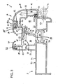
- Figures 1 and 2 show in cross section the lower cross member of the opening 1 associated with the frame 3, the opening 1 being in the closed position, the Figure 3 showing in cross section an amount of the opening 1.
- the opening 1 is capable of being open towards the interior I of a construction receiving the opening.
- the invention could be applied to an opening 1 capable of being open to the outside E of the building.
- the glazing 2 is an insulating double glazing comprising an interior glass 5, a exterior window 6, a space 7 separating the two windows 5, 6, and a spacer peripheral 8.
- the glazing 2 defines a median plane P.
- At least one amount or a cross member of the opening 1 is made from a set of profiles according to the invention.
- the profile set includes a first profile 9, made of aluminum, and a second profile 10, made of plastic, in particular PVC comprising glass fibers. Profiles 9, 10 are hollow and obtained for example by spinning or extrusion.
- the first section 9 is first described.
- the first profile 9 has, in cross section, the general shape of an L having a first branch 11 and a second branch 12, substantially perpendicular. The angles at the connection between the two branches 11, 12 are rounded.
- the first profile 9 is intended to give a good rigidity to the profile assembly.
- a direction D1 is defined which is substantially parallel to the first branch 11 and a direction D2 substantially parallel to the second branch 12 of the first profile 9 constituting a cross member, when the opening 1 is in the closed position ( Figures 1 and 2).
- the directions D1, D2 are fixed relative to the masonry, the branches 11, 12 of the first profile 9 no longer parallel to D1, respectively at D2, when the door 1 is in the open position.
- D3 is the direction in which extend the sections 9, 10. References to directions D1, D2, D3 are to be considered in relation to Figures 1 and 2.
- the first branch 11 firstly has a first side wall 13, and a second side wall 14, located between the first side wall 13 and the second branch 12 of the first profile, said side walls 13, 14 being substantially parallel to direction D1.
- a third wall 15 extends from the free end of the second side wall 14 in direction D2, towards the second branch 12 of the first profile 9.
- a projecting wall 16 forming a support wall, extends from the third wall 15 in direction D1, moving away from the second branch 12.
- the support wall 16 is located substantially in the middle of the third wall 15.
- the first branch 11 also includes an interior wall 17 extending between the first and second side walls 13, 14.
- the interior wall 17 is substantially parallel to the direction D1, and located at a distance from the free ends of the side walls 13, 14.
- the wall interior 17 comprises, starting from the first side wall 13 and going towards the second side wall 14, a first portion 17a substantially parallel to the second branch 12, located at a distance from the free ends of the side walls 13, 14, and a second oblique portion 17b, connecting the end free from the first portion to the free end of the second side wall 14.
- the first branch 11 of the first profile 9 has, towards its part extreme free, a cavity 18 delimited by the inner wall 17 and by the first and second side walls 13, 14.
- the cavity 18 has a cross section substantially rectangular.
- the first side wall 13 - as well as the second side wall 14 in the first embodiment - includes first latching means 19, directed towards the interior of the cavity 18.
- the support wall 16 also comprises latching means 20, intended to absorb the production tolerances of the first and second profiles 9, 10, for a better support.
- the first branch 11 comprises, on its internal face, a housing 21, of substantially circular cross section extending longitudinally, said housing 21 being located inside the first branch 11, near of the inner wall 17, and being intended to receive a fixing member.
- the second branch 12 of the first profile 9 is able to cooperate with the standing 3.
- the second branch 12 has a wall end 22, substantially parallel to direction D1, capable of being crossed by the rotation member 4 ( Figure 3).
- the second branch 12 comprises, towards its free end part, and on its external face intended to be placed in gaze of the frame 3, a groove 23 capable of receiving a seal 24.
- the second branch 12 comprises an interior partition 25, substantially parallel to direction D1.
- a cavity 26 is thus defined between the partition 25 and the end wall 22.
- the second section 10 is now described.
- the second profile 10 is rigid. It has, in cross section, the shape general of a U and comprises a wall forming a bottom 27, as well as a first and second wings 28, 29 defining a groove 30.
- the first wing 28 of the second profile 10 comprises, on its outside face the groove 30, second latching means 31 complementary to the first latching means 19 of the first profile 9.
- the second latching means 31 comprise at least one wall attachment 32 extending from the first wing 28 of the second profile 10 out of throat 30.
- the second means latching 31 comprise two hooking walls 32, substantially parallel to the bottom 27.
- the second latching means 31 comprise a hooking wall 32 substantially forming a U with the first wing 28.
- the second latching means 31 include a hooking wall 32 oblique to the first wing 28.
- the attachment wall (s) 32 have a snap-fit spout 33 (Figures 1 and 3), or a groove ( Figure 2), intended (e) to cooperate with the first latching means 19 of the first profile 9.
- the second profile 10 also includes a retaining wall 34 extending substantially parallel to the bottom 27 of the groove 30 and at a distance of the latter, opposite the groove 30.
- the retaining wall 34 is linked to the bottom 27 at a connecting zone 35 located substantially in the middle of said bottom 27, transversely.
- the retaining wall 34 extends substantially to the right of the first wing 28.
- the retaining wall 34 may include complementary latching means latching means 20 of the support wall 16.
- the second profile 10 further comprises an orifice 36 located in the wall forming bottom 27, at the level of the connection zone 35.
- the orifice 36 extends longitudinally and is intended to receive a fixing member.
- the second profile 10 comprises a partition wall 37 extending substantially perpendicular to the bottom 27 of the groove 30 in the direction opposite the wings 28, 29.
- the second profile 10 is intended to be associated with the first profile 9 substantially in the extension of the first branch 11, so that the bottom 27 of groove 30 extends substantially parallel to the second wall lateral 14 of the first branch 11, and the opening of the groove 30 is directed opposite the second branch 12 of the first section 9.
- the first and second sections 9, 10 are assembled by cooperation of the first and second latching means 19, 31.
- the groove 30 is intended to receive the glazing 2, so that the plane P is substantially parallel to direction D2.
- the support wall 16 of the first profile 9 is engaged in the space formed between the bottom 27 of the groove 30 and the retaining wall 34. This ensures better support for the glazing 2.
- the seal 39 is coextruded and forms a stop, while the seal 40 is a seal to be stuffed or clammed in place after the glazing 2 has been inserted in the throat 30, by depression.
- the glazing is represented in dotted lines, in the position it is intended to occupy, the seal 40 then being compressed.
- the seals 39, 40 are clipped, glued or coextruded on the wings 28, 29, and include a flexible lip 41 covered with a film 42 slippery, as well as a portion 43 of compressible polyurethane foam intended, when the glazing 2 is inserted in the groove 30, to be applied against the face of the wings 28, 29 directed towards the inside of the groove 30.
- the seals 39, 40 may include rigid notches 44 allowing better holding on the wings 28, 29.
- the seals 39, 40 can be made of PVC and coextruded with the second profile 10. They are intended to be bent during the insertion of the glazing 2. One of the two seals 39, 40 more specifically ensures the role of setting the glazing 2. An additional element 39 ′, also forming a seal, can be planned, and put in place by clipping.
- the seal 40 located on the wing 29 not linked to the first profile 9 also includes an additional part 45, located outside the groove 30, and intended to come to bear on the frame 3.
- the first and second sections 9, 10 are produced separately by spinning or extrusion, then snap-on, as previously described.
- the uprights and crossbars of the opening 1 are then cut in the assembly formed by the profiles 9, 10 thus assembled, along a plane forming an angle close to 45 ° with the axis of said sections 9, 10.
- the glazing 2 is then engaged in the groove 30 of the second profile 10 of each of the two uprights - respectively of the two crosspieces. Finally, we engages the free arms of the brackets 46 linked to the crosspieces - respectively to the uprights - in the extreme parts of the uprights - sleepers respectively - carrying glazing 2, in the second branch 11 of the first profile 9, so as to form a frame.
- eccentric pins 47 comprising notches and cooperating, on the one hand, with holes 48 made in the square 46 and, on the other hand, with holes 49 practiced in the second branch 12 of the first section 9 constituting said amount and said cross. So, by acting on the eccentric pins 47, we gradually bring the adjacent upright and crossbar closer together, and we get a perfectly tight assembly, as illustrated in figure 5.
- the brackets 46 and the pins 47 can be made of polyamide or Nylon ®, and include glass fibers.
- the amount and the crosspiece adjacent to each other are fixed by means of assembly members, such as screws 50, engaged in means of reception provided on the first and second profiles 9, 10.
- These means of reception include on the one hand orifices 51 provided on the upright - respectively the cross - and on the other hand the orifice 36 and the housing 21 of the crosspiece - respectively of the upright - adjacent (e).
- the mounting and fixing are carried out by three regularly distributed points, at know the cavity 26 receiving the bracket 46, the orifice 36 and the housing 21 receiving the screws 50, which allows very good positioning and excellent support.
- the opening may include means capable of cooperating on the one hand with the bars 57 of the frame 3 and on the other hand with the flexible lip 38 of the second profile 10 constituting an upright or a cross member of the opening 1.
- These means can be constituted by a seal 58 ( Figures 1 and 2) or by a wall 59 projecting from a bar 57 towards the second profile 10.
- direction D2 there are also two couples of rooms 60, 62 and 61, 63, which further improves the quality of the opening.
Landscapes
- Civil Engineering (AREA)
- Structural Engineering (AREA)
- Engineering & Computer Science (AREA)
- Wing Frames And Configurations (AREA)
- Securing Of Glass Panes Or The Like (AREA)
- Transplanting Machines (AREA)
- Turbine Rotor Nozzle Sealing (AREA)
- Connection Of Plates (AREA)
- Joining Of Building Structures In Genera (AREA)
- Finishing Walls (AREA)
- Forms Removed On Construction Sites Or Auxiliary Members Thereof (AREA)
- Specific Sealing Or Ventilating Devices For Doors And Windows (AREA)
- Ladders (AREA)
- Bending Of Plates, Rods, And Pipes (AREA)
- Stringed Musical Instruments (AREA)
Applications Claiming Priority (2)
| Application Number | Priority Date | Filing Date | Title |
|---|---|---|---|
| FR0202156A FR2836176B1 (fr) | 2002-02-20 | 2002-02-20 | Ensemble de profiles pour la realisation d'un ouvrant |
| FR0202156 | 2002-02-20 |
Publications (3)
| Publication Number | Publication Date |
|---|---|
| EP1338745A2 true EP1338745A2 (de) | 2003-08-27 |
| EP1338745A3 EP1338745A3 (de) | 2004-09-01 |
| EP1338745B1 EP1338745B1 (de) | 2009-10-28 |
Family
ID=27636349
Family Applications (1)
| Application Number | Title | Priority Date | Filing Date |
|---|---|---|---|
| EP03290418A Expired - Lifetime EP1338745B1 (de) | 2002-02-20 | 2003-02-20 | Profilsatz für die Flügelherstellung |
Country Status (4)
| Country | Link |
|---|---|
| EP (1) | EP1338745B1 (de) |
| AT (1) | ATE447086T1 (de) |
| DE (1) | DE60329798D1 (de) |
| FR (1) | FR2836176B1 (de) |
Cited By (5)
| Publication number | Priority date | Publication date | Assignee | Title |
|---|---|---|---|---|
| EP1544401A3 (de) * | 2003-12-18 | 2006-09-20 | Reynaers Aluminium, naamloze vennootschap | Fenster, Tür und dergleichen mit darin angewendetes Kunststoffprofil |
| ITCL20090013A1 (it) * | 2009-09-15 | 2011-03-16 | Porte Frigorifere Ind S R L | Profilo bordo anta in alluminio e pvc ad incastro per taglio termico |
| GB2487910A (en) * | 2011-02-04 | 2012-08-15 | Bowater Building Products Ltd | Corner connector and frame assembly |
| FR3007785A1 (fr) * | 2013-07-01 | 2015-01-02 | Sapa Building System | Chassis dormant pour ouverture de batiment |
| WO2019130367A1 (en) * | 2017-12-29 | 2019-07-04 | Permasteelisa S.P.A. | Window frame |
Families Citing this family (1)
| Publication number | Priority date | Publication date | Assignee | Title |
|---|---|---|---|---|
| FR2880055B1 (fr) | 2004-12-24 | 2008-09-26 | Groupe Janneau Ind Soc Par Act | Ouvrant, notamment pour fenetre ou porte-fenetre a frappe |
Family Cites Families (12)
| Publication number | Priority date | Publication date | Assignee | Title |
|---|---|---|---|---|
| FR1380715A (fr) * | 1963-10-24 | 1964-12-04 | Schwartz Hautmont Atel Const | Perfectionnements au montage d'éléments de construction sur des éléments d'assemblage et éléments pour ce montage |
| FR1466532A (fr) * | 1965-12-09 | 1967-01-20 | Tech Jean Prouve | Fenêtres à la française avec battants susceptibles d'être ouverts indifférement par la droite ou par la gauche |
| CH564676A5 (de) * | 1972-05-08 | 1975-07-31 | Goetz Metallbau Gmbh | |
| DE3046991A1 (de) * | 1980-12-12 | 1982-07-15 | Arnold 7211 Frittlingen Neher | Fenster, insbesondere leichtes vorsatzfenster |
| DE3049605A1 (de) * | 1980-12-31 | 1982-07-29 | Ekkehard Prof. Dipl.-Ing. 8000 München Fahr | Rahmen-fluegel-aufbau fuer fenster, tueren o.dgl. |
| DE4010081A1 (de) * | 1990-03-29 | 1991-10-02 | Hugo Selnar | Fenster, tuer o. dgl. fuer gebaeude mit einer verglasung |
| FR2708501B1 (fr) * | 1993-08-04 | 1997-04-11 | Daniel Colombo | Procédé de façonnage de profilés, de fabrication de cadres, cadres et profilés. |
| FR2760036B1 (fr) * | 1997-02-21 | 1999-05-14 | Ouest Alu | Fenetre ou porte-fenetre a frappe, a ouvrant(s) cache(s) |
| DE29811431U1 (de) * | 1998-06-30 | 1998-10-01 | Jostock, Leander, 33615 Bielefeld | Fenster, Tür, Fassadenelement o.dgl. |
| FR2802969B1 (fr) | 1999-12-23 | 2003-04-11 | Ouest Alu | Fenetre ou porte-fenetre a ouvrant(s) cache (s) avec isolation thermique |
| FR2802968A1 (fr) | 1999-12-23 | 2001-06-29 | Ouest Alu | Fenetre ou porte-fenetre a ouvrant(s) cache(s) avec rupture de pont thermique |
| DE19963233A1 (de) * | 1999-12-27 | 2001-06-28 | Raico Bautechnik Gmbh | Rahmen für Fenster oder Türe |
-
2002
- 2002-02-20 FR FR0202156A patent/FR2836176B1/fr not_active Expired - Fee Related
-
2003
- 2003-02-20 DE DE60329798T patent/DE60329798D1/de not_active Expired - Fee Related
- 2003-02-20 EP EP03290418A patent/EP1338745B1/de not_active Expired - Lifetime
- 2003-02-20 AT AT03290418T patent/ATE447086T1/de not_active IP Right Cessation
Cited By (6)
| Publication number | Priority date | Publication date | Assignee | Title |
|---|---|---|---|---|
| EP1544401A3 (de) * | 2003-12-18 | 2006-09-20 | Reynaers Aluminium, naamloze vennootschap | Fenster, Tür und dergleichen mit darin angewendetes Kunststoffprofil |
| ITCL20090013A1 (it) * | 2009-09-15 | 2011-03-16 | Porte Frigorifere Ind S R L | Profilo bordo anta in alluminio e pvc ad incastro per taglio termico |
| GB2487910A (en) * | 2011-02-04 | 2012-08-15 | Bowater Building Products Ltd | Corner connector and frame assembly |
| GB2487910B (en) * | 2011-02-04 | 2017-05-10 | Bowater Building Products Ltd | window or door frame |
| FR3007785A1 (fr) * | 2013-07-01 | 2015-01-02 | Sapa Building System | Chassis dormant pour ouverture de batiment |
| WO2019130367A1 (en) * | 2017-12-29 | 2019-07-04 | Permasteelisa S.P.A. | Window frame |
Also Published As
| Publication number | Publication date |
|---|---|
| DE60329798D1 (de) | 2009-12-10 |
| ATE447086T1 (de) | 2009-11-15 |
| EP1338745B1 (de) | 2009-10-28 |
| FR2836176B1 (fr) | 2005-01-21 |
| EP1338745A3 (de) | 2004-09-01 |
| FR2836176A1 (fr) | 2003-08-22 |
Similar Documents
| Publication | Publication Date | Title |
|---|---|---|
| EP2078817A1 (de) | Isolierprofil für Öffnungsflügel mit Schiebeöffnung, Bauprofil und Öffnungsflügel, der ein solches Isolierprofil umfasst | |
| FR3067738A1 (fr) | Clip de montage d'une menuiserie dans une ouverture | |
| FR2768173A1 (fr) | Perfectionnement aux fenetres ou portes-fenetres a frappe, du type a ouvrant(s) cache(s) | |
| CH693858A5 (fr) | Fenêtre ou porte-fenêtre à frappe à ouvrant(s) caché(s) | |
| EP1338745B1 (de) | Profilsatz für die Flügelherstellung | |
| CH652167A5 (fr) | Aerateur. | |
| FR2793515A1 (fr) | Panneau a double vitrage et procede de montage d'un tel panneau | |
| WO2012104556A1 (fr) | Panneau vitré à vitrages multiples, cadre intermédiaire et châssis, procédé de fabrication et kit de préparation d'un tel panneau vitré | |
| EP2186985B1 (de) | Gebäudeverschlusselement mit einer thermisch getrennten Zarge, die mit einem L-förmigen Dichtungsprofil ausgestattet ist | |
| EP3789575B1 (de) | Rahmenprofil zur aufnahme einer verkleidung | |
| FR2919889A1 (fr) | Element de chassis composite pour la realisation de chassis dormants et/ou ouvrants de portes, fenetres ou analogues | |
| FR2760036A1 (fr) | Fenetre ou porte-fenetre a frappe, a ouvrant(s) cache(s) | |
| FR2734310A1 (fr) | Perfectionnement aux menuiseries en matiere plastique | |
| FR2644506A1 (fr) | Dispositif support des ensembles de vitrage et notamment double vitrage adaptables pour menuiseries metalliques ou autres sur cadre en bois pour toutes ouvertures et tous types de construction | |
| FR2850423A1 (fr) | Dispositif de joint pour systeme de fermeture de baie a au moins un vantail coulissant | |
| FR2784708A1 (fr) | Fenetre ou porte-fenetre a frappe a ouvrant(s) cache(s) | |
| FR2509361A1 (fr) | Cadre d'adaptation realise en profiles, pour vitrage | |
| EP2003279B1 (de) | Klappfenster oder Ähnliches mit Rahmen, mit verdecktem Öffnungsflügel | |
| EP1991752B1 (de) | Anordnung aus einer mehrfachverglasungseinheit und einem profil sowie profil für eine verglasungseinheit | |
| FR2526475A1 (fr) | Boiserie avec ouvrant a double vitrage, a fort affaiblissement acoustique, pour fenetres ou autres ouvertures | |
| FR2658860A1 (fr) | Profile pour la realisation de fermetures metalliques ayant des battants a plusieurs jours. | |
| FR2482999A1 (fr) | Dispositif comportant un profile special en matiere plastique et destine a la realisation d'un triple vitrage par adjonction en survitre d'un double vitrage a un vitrage existant | |
| FR2667106A1 (fr) | Profile d'etancheite pour caravane, vehicule de camping ou analogue. | |
| WO2000008289A1 (fr) | Structure de battement central pour porte ou fenetre metallique a frappe a deux vantaux | |
| FR2726306A1 (fr) | Ensemble de facade du type facade-rideau |
Legal Events
| Date | Code | Title | Description |
|---|---|---|---|
| PUAI | Public reference made under article 153(3) epc to a published international application that has entered the european phase |
Free format text: ORIGINAL CODE: 0009012 |
|
| AK | Designated contracting states |
Designated state(s): AT BE BG CH CY CZ DE DK EE ES FI FR GB GR HU IE IT LI LU MC NL PT SE SI SK TR |
|
| AX | Request for extension of the european patent |
Extension state: AL LT LV MK RO |
|
| PUAL | Search report despatched |
Free format text: ORIGINAL CODE: 0009013 |
|
| AK | Designated contracting states |
Kind code of ref document: A3 Designated state(s): AT BE BG CH CY CZ DE DK EE ES FI FR GB GR HU IE IT LI LU MC NL PT SE SI SK TR |
|
| AX | Request for extension of the european patent |
Extension state: AL LT LV MK RO |
|
| RIC1 | Information provided on ipc code assigned before grant |
Ipc: 7E 06B 3/54 B Ipc: 7E 06B 3/30 A Ipc: 7E 06B 3/263 B |
|
| 17P | Request for examination filed |
Effective date: 20050127 |
|
| AKX | Designation fees paid |
Designated state(s): AT BE BG CH CY CZ DE DK EE ES FI FR GB GR HU IE IT LI LU MC NL PT SE SI SK TR |
|
| GRAJ | Information related to disapproval of communication of intention to grant by the applicant or resumption of examination proceedings by the epo deleted |
Free format text: ORIGINAL CODE: EPIDOSDIGR1 |
|
| GRAP | Despatch of communication of intention to grant a patent |
Free format text: ORIGINAL CODE: EPIDOSNIGR1 |
|
| GRAP | Despatch of communication of intention to grant a patent |
Free format text: ORIGINAL CODE: EPIDOSNIGR1 |
|
| GRAS | Grant fee paid |
Free format text: ORIGINAL CODE: EPIDOSNIGR3 |
|
| GRAA | (expected) grant |
Free format text: ORIGINAL CODE: 0009210 |
|
| AK | Designated contracting states |
Kind code of ref document: B1 Designated state(s): AT BE BG CH CY CZ DE DK EE ES FI FR GB GR HU IE IT LI LU MC NL PT SE SI SK TR |
|
| REG | Reference to a national code |
Ref country code: GB Ref legal event code: FG4D Free format text: NOT ENGLISH |
|
| REG | Reference to a national code |
Ref country code: CH Ref legal event code: EP |
|
| REG | Reference to a national code |
Ref country code: IE Ref legal event code: FG4D |
|
| REF | Corresponds to: |
Ref document number: 60329798 Country of ref document: DE Date of ref document: 20091210 Kind code of ref document: P |
|
| NLV1 | Nl: lapsed or annulled due to failure to fulfill the requirements of art. 29p and 29m of the patents act | ||
| PG25 | Lapsed in a contracting state [announced via postgrant information from national office to epo] |
Ref country code: PT Free format text: LAPSE BECAUSE OF FAILURE TO SUBMIT A TRANSLATION OF THE DESCRIPTION OR TO PAY THE FEE WITHIN THE PRESCRIBED TIME-LIMIT Effective date: 20100301 Ref country code: ES Free format text: LAPSE BECAUSE OF FAILURE TO SUBMIT A TRANSLATION OF THE DESCRIPTION OR TO PAY THE FEE WITHIN THE PRESCRIBED TIME-LIMIT Effective date: 20100208 Ref country code: SE Free format text: LAPSE BECAUSE OF FAILURE TO SUBMIT A TRANSLATION OF THE DESCRIPTION OR TO PAY THE FEE WITHIN THE PRESCRIBED TIME-LIMIT Effective date: 20091028 Ref country code: FI Free format text: LAPSE BECAUSE OF FAILURE TO SUBMIT A TRANSLATION OF THE DESCRIPTION OR TO PAY THE FEE WITHIN THE PRESCRIBED TIME-LIMIT Effective date: 20091028 |
|
| REG | Reference to a national code |
Ref country code: IE Ref legal event code: FD4D |
|
| PG25 | Lapsed in a contracting state [announced via postgrant information from national office to epo] |
Ref country code: SI Free format text: LAPSE BECAUSE OF FAILURE TO SUBMIT A TRANSLATION OF THE DESCRIPTION OR TO PAY THE FEE WITHIN THE PRESCRIBED TIME-LIMIT Effective date: 20091028 Ref country code: CY Free format text: LAPSE BECAUSE OF FAILURE TO SUBMIT A TRANSLATION OF THE DESCRIPTION OR TO PAY THE FEE WITHIN THE PRESCRIBED TIME-LIMIT Effective date: 20091028 |
|
| PG25 | Lapsed in a contracting state [announced via postgrant information from national office to epo] |
Ref country code: AT Free format text: LAPSE BECAUSE OF FAILURE TO SUBMIT A TRANSLATION OF THE DESCRIPTION OR TO PAY THE FEE WITHIN THE PRESCRIBED TIME-LIMIT Effective date: 20091028 |
|
| PG25 | Lapsed in a contracting state [announced via postgrant information from national office to epo] |
Ref country code: EE Free format text: LAPSE BECAUSE OF FAILURE TO SUBMIT A TRANSLATION OF THE DESCRIPTION OR TO PAY THE FEE WITHIN THE PRESCRIBED TIME-LIMIT Effective date: 20091028 Ref country code: DK Free format text: LAPSE BECAUSE OF FAILURE TO SUBMIT A TRANSLATION OF THE DESCRIPTION OR TO PAY THE FEE WITHIN THE PRESCRIBED TIME-LIMIT Effective date: 20091028 Ref country code: IE Free format text: LAPSE BECAUSE OF FAILURE TO SUBMIT A TRANSLATION OF THE DESCRIPTION OR TO PAY THE FEE WITHIN THE PRESCRIBED TIME-LIMIT Effective date: 20091028 Ref country code: BG Free format text: LAPSE BECAUSE OF FAILURE TO SUBMIT A TRANSLATION OF THE DESCRIPTION OR TO PAY THE FEE WITHIN THE PRESCRIBED TIME-LIMIT Effective date: 20100128 |
|
| BERE | Be: lapsed |
Owner name: JH INDUSTRIES Effective date: 20100228 |
|
| PG25 | Lapsed in a contracting state [announced via postgrant information from national office to epo] |
Ref country code: CZ Free format text: LAPSE BECAUSE OF FAILURE TO SUBMIT A TRANSLATION OF THE DESCRIPTION OR TO PAY THE FEE WITHIN THE PRESCRIBED TIME-LIMIT Effective date: 20091028 Ref country code: SK Free format text: LAPSE BECAUSE OF FAILURE TO SUBMIT A TRANSLATION OF THE DESCRIPTION OR TO PAY THE FEE WITHIN THE PRESCRIBED TIME-LIMIT Effective date: 20091028 |
|
| PLBE | No opposition filed within time limit |
Free format text: ORIGINAL CODE: 0009261 |
|
| STAA | Information on the status of an ep patent application or granted ep patent |
Free format text: STATUS: NO OPPOSITION FILED WITHIN TIME LIMIT |
|
| REG | Reference to a national code |
Ref country code: CH Ref legal event code: PL |
|
| 26N | No opposition filed |
Effective date: 20100729 |
|
| GBPC | Gb: european patent ceased through non-payment of renewal fee |
Effective date: 20100220 |
|
| PG25 | Lapsed in a contracting state [announced via postgrant information from national office to epo] |
Ref country code: MC Free format text: LAPSE BECAUSE OF NON-PAYMENT OF DUE FEES Effective date: 20100301 Ref country code: CH Free format text: LAPSE BECAUSE OF NON-PAYMENT OF DUE FEES Effective date: 20100228 Ref country code: GR Free format text: LAPSE BECAUSE OF FAILURE TO SUBMIT A TRANSLATION OF THE DESCRIPTION OR TO PAY THE FEE WITHIN THE PRESCRIBED TIME-LIMIT Effective date: 20100129 Ref country code: LI Free format text: LAPSE BECAUSE OF NON-PAYMENT OF DUE FEES Effective date: 20100228 |
|
| PG25 | Lapsed in a contracting state [announced via postgrant information from national office to epo] |
Ref country code: DE Free format text: LAPSE BECAUSE OF NON-PAYMENT OF DUE FEES Effective date: 20100901 Ref country code: BE Free format text: LAPSE BECAUSE OF NON-PAYMENT OF DUE FEES Effective date: 20100228 |
|
| PG25 | Lapsed in a contracting state [announced via postgrant information from national office to epo] |
Ref country code: IT Free format text: LAPSE BECAUSE OF FAILURE TO SUBMIT A TRANSLATION OF THE DESCRIPTION OR TO PAY THE FEE WITHIN THE PRESCRIBED TIME-LIMIT Effective date: 20091028 Ref country code: GB Free format text: LAPSE BECAUSE OF NON-PAYMENT OF DUE FEES Effective date: 20100220 |
|
| PG25 | Lapsed in a contracting state [announced via postgrant information from national office to epo] |
Ref country code: HU Free format text: LAPSE BECAUSE OF FAILURE TO SUBMIT A TRANSLATION OF THE DESCRIPTION OR TO PAY THE FEE WITHIN THE PRESCRIBED TIME-LIMIT Effective date: 20100429 Ref country code: LU Free format text: LAPSE BECAUSE OF NON-PAYMENT OF DUE FEES Effective date: 20100220 Ref country code: NL Free format text: LAPSE BECAUSE OF FAILURE TO SUBMIT A TRANSLATION OF THE DESCRIPTION OR TO PAY THE FEE WITHIN THE PRESCRIBED TIME-LIMIT Effective date: 20091028 |
|
| PG25 | Lapsed in a contracting state [announced via postgrant information from national office to epo] |
Ref country code: TR Free format text: LAPSE BECAUSE OF FAILURE TO SUBMIT A TRANSLATION OF THE DESCRIPTION OR TO PAY THE FEE WITHIN THE PRESCRIBED TIME-LIMIT Effective date: 20091028 |
|
| REG | Reference to a national code |
Ref country code: FR Ref legal event code: PLFP Year of fee payment: 14 |
|
| REG | Reference to a national code |
Ref country code: FR Ref legal event code: PLFP Year of fee payment: 15 |
|
| REG | Reference to a national code |
Ref country code: FR Ref legal event code: PLFP Year of fee payment: 16 |
|
| PGFP | Annual fee paid to national office [announced via postgrant information from national office to epo] |
Ref country code: FR Payment date: 20190228 Year of fee payment: 17 |
|
| PG25 | Lapsed in a contracting state [announced via postgrant information from national office to epo] |
Ref country code: FR Free format text: LAPSE BECAUSE OF NON-PAYMENT OF DUE FEES Effective date: 20200229 |