EP1338761A1 - Engrenage à vis sans fin pour un déphaseur variable - Google Patents
Engrenage à vis sans fin pour un déphaseur variable Download PDFInfo
- Publication number
- EP1338761A1 EP1338761A1 EP03250871A EP03250871A EP1338761A1 EP 1338761 A1 EP1338761 A1 EP 1338761A1 EP 03250871 A EP03250871 A EP 03250871A EP 03250871 A EP03250871 A EP 03250871A EP 1338761 A1 EP1338761 A1 EP 1338761A1
- Authority
- EP
- European Patent Office
- Prior art keywords
- drive wheel
- plate
- camshaft
- phaser
- retard
- Prior art date
- Legal status (The legal status is an assumption and is not a legal conclusion. Google has not performed a legal analysis and makes no representation as to the accuracy of the status listed.)
- Granted
Links
- RDYMFSUJUZBWLH-UHFFFAOYSA-N endosulfan Chemical compound C12COS(=O)OCC2C2(Cl)C(Cl)=C(Cl)C1(Cl)C2(Cl)Cl RDYMFSUJUZBWLH-UHFFFAOYSA-N 0.000 title claims abstract description 43
- 230000008878 coupling Effects 0.000 claims description 6
- 238000010168 coupling process Methods 0.000 claims description 6
- 238000005859 coupling reaction Methods 0.000 claims description 6
- 238000002485 combustion reaction Methods 0.000 description 5
- 239000003921 oil Substances 0.000 description 2
- 238000006073 displacement reaction Methods 0.000 description 1
- 230000009977 dual effect Effects 0.000 description 1
- 230000000694 effects Effects 0.000 description 1
- 238000000034 method Methods 0.000 description 1
- 239000010705 motor oil Substances 0.000 description 1
- 230000007935 neutral effect Effects 0.000 description 1
Images


Classifications
-
- F—MECHANICAL ENGINEERING; LIGHTING; HEATING; WEAPONS; BLASTING
- F01—MACHINES OR ENGINES IN GENERAL; ENGINE PLANTS IN GENERAL; STEAM ENGINES
- F01L—CYCLICALLY OPERATING VALVES FOR MACHINES OR ENGINES
- F01L1/00—Valve-gear or valve arrangements, e.g. lift-valve gear
- F01L1/34—Valve-gear or valve arrangements, e.g. lift-valve gear characterised by the provision of means for changing the timing of the valves without changing the duration of opening and without affecting the magnitude of the valve lift
- F01L1/344—Valve-gear or valve arrangements, e.g. lift-valve gear characterised by the provision of means for changing the timing of the valves without changing the duration of opening and without affecting the magnitude of the valve lift changing the angular relationship between crankshaft and camshaft, e.g. using helicoidal gear
-
- F—MECHANICAL ENGINEERING; LIGHTING; HEATING; WEAPONS; BLASTING
- F01—MACHINES OR ENGINES IN GENERAL; ENGINE PLANTS IN GENERAL; STEAM ENGINES
- F01L—CYCLICALLY OPERATING VALVES FOR MACHINES OR ENGINES
- F01L1/00—Valve-gear or valve arrangements, e.g. lift-valve gear
- F01L1/34—Valve-gear or valve arrangements, e.g. lift-valve gear characterised by the provision of means for changing the timing of the valves without changing the duration of opening and without affecting the magnitude of the valve lift
- F01L1/344—Valve-gear or valve arrangements, e.g. lift-valve gear characterised by the provision of means for changing the timing of the valves without changing the duration of opening and without affecting the magnitude of the valve lift changing the angular relationship between crankshaft and camshaft, e.g. using helicoidal gear
- F01L1/352—Valve-gear or valve arrangements, e.g. lift-valve gear characterised by the provision of means for changing the timing of the valves without changing the duration of opening and without affecting the magnitude of the valve lift changing the angular relationship between crankshaft and camshaft, e.g. using helicoidal gear using bevel or epicyclic gear
-
- Y—GENERAL TAGGING OF NEW TECHNOLOGICAL DEVELOPMENTS; GENERAL TAGGING OF CROSS-SECTIONAL TECHNOLOGIES SPANNING OVER SEVERAL SECTIONS OF THE IPC; TECHNICAL SUBJECTS COVERED BY FORMER USPC CROSS-REFERENCE ART COLLECTIONS [XRACs] AND DIGESTS
- Y10—TECHNICAL SUBJECTS COVERED BY FORMER USPC
- Y10T—TECHNICAL SUBJECTS COVERED BY FORMER US CLASSIFICATION
- Y10T74/00—Machine element or mechanism
- Y10T74/19—Gearing
- Y10T74/19023—Plural power paths to and/or from gearing
- Y10T74/19047—Worm-type gearing
Definitions
- the invention pertains to the field of control of valve timing in internal combustion engines. More particularly, the invention pertains to a device for varying the phase relationship between a camshaft and a camshaft drive.
- phasers move the cam position relative to the crankshaft, usually by using engine oil pressure.
- oil pressure is low, or at engine cranking, the phaser cannot move to the advance position because the cam mean torque is too high for the low oil pressure to overcome. If the engine was stopped in this state, the phaser would be in the wrong position.
- a third example is Suga's "Valve Timing Control Apparatus," U.S. Patent No. 5,156,119, issued Oct. 20, 1992, which shows a pair of worm gears shifting the phaser relative to the crankshaft using engine power.
- the worms are driven by an axial shifting plate, which is driven by friction wheels extending out of the phaser.
- the friction wheels rub on friction disks that are either in front or behind the phaser to rotate the two wheels one way or the other.
- a solenoid pulls or pushes on the mounting of the friction disks, pushing one way or the other against the two wheels.
- a phaser for adjusting the timing between a camshaft and a crankshaft consist of an outer housing having internal and external teeth and an inner housing connected to the camshaft. The outer teeth couple to the cam drive - the timing chain, timing belt or timing gears.
- a worm mounted on the inner housing is meshed with the internal teeth of the outer housing.
- the worm gear is connected to one or two drive wheels, which are rotated by contact with stationary plates. The plates are moved by electromagnetic coils to contact the drive wheel or wheels, and turn them in one direction or the other.
- the actuators are activated by an engine control unit.
- the plates can be mounted concentrically on one side of the phaser, or on opposite sides.
- an internal combustion engine has a crankshaft, to which is driven by the connecting rods of the pistons, and one or more camshafts (17), which actuate the intake and the exhaust valves on the cylinders.
- the timing gear on the camshaft (17) is connected to the crankshaft with a timing drive, such as a chain (11), as shown in the figures, or a belt or gears.
- camshaft may be the only camshaft of a single camshaft engine, either of the overhead camshaft type or the in-block camshaft type, or one of two (the intake valve operating camshaft or the exhaust valve operating camshaft) of a dual camshaft engine, or one of four camshafts in a "V" type overhead cam engine, two for each bank of cylinders.
- phaser In a variable cam timing (VCT) system, the timing gear on the camshaft (17) is replaced by a variable angle coupling known as a "phaser" (25), having a rotor connected to the camshaft (17) and a housing connected to (or forming) the timing gear, which allows the camshaft (17) to rotate independently of the timing gear, within angular limits, to change the relative timing of the camshaft (17) and crankshaft.
- phaser includes the housing and the rotor, and all of the parts to control the relative angular position of the housing and rotor, to allow the timing of the camshaft (17) to be offset from the crankshaft. In any of the multiple-camshaft engines, it will be understood that there would preferably be one phaser (25) on each camshaft (17), as is known to the art.
- Figure 1 shows an embodiment of the invention using what will be termed "double sided control”.
- the inner housing (18) of the phaser is attached to the camshaft (17) by a mounting plate (fig. 2, (26)), which has an inner cavity (27) for housing part of the control mechanism, as will be described in the discussion of figure 2, below.
- the outer surface of the outer housing (12) has outer teeth (10) for coupling to timing chain (11).
- the outer housing (18) also has inside teeth (9), which couple to worm (13), which can be driven by gear (14).
- the gear (14) being smaller in diameter than the worm (13), is at a mechanical disadvantage, and is preferably beveled.
- the gear (14) meshes with an intermediate gear (15), which is also preferably beveled and which in turn meshes with drive wheel (16), which is mounted to one side of the axis of the camshaft.
- the intermediate gear (15) and drive wheel (16) are angle cut to mesh with each other, the axes of the two being at right angles, and the axis of the drive wheel (16) being parallel to the axis of the worm (13).
- the intermediate gear (15) provides a means for coupling the rotation of the drive wheel (16) to the gear (14), and thus to the worm (13). It will be recognized by one skilled in the art that the axis of rotation of the drive wheel (16) could be perpendicular or parallel to that of the worm (13), or other arrangements, within the teachings of the invention, so long as the drive wheel is coupled to the worm for rotation.
- the worm (13), gear (14), intermediate gear (15) and drive wheel (16) are all mounted to the inner housing (18), and thus rotate with the camshaft (17).
- the drive wheel (16) is actuated by a double-sided control mechanism, which is removed in figure 1 to show the mechanism more clearly, and which is shown in section in figure 2.
- the double sided control assembly is made up of an advance plate (25) and a retard plate (24), connected by a shaft (28).
- the advance (25) and retard (24) plates are on opposite sides of the inner housing (18) of the phaser, and the shaft (28) is of sufficient length that when the mechanism is centered by springs (20), neither plate (24) or (25) contacts the drive wheel (16).
- Actuating plate (23) extends forward and radially outward from retard plate (24), and is connected to the control assembly such that when the actuating plate (23) is moved forward, the advance plate (25) contacts the rearward edge of the drive wheel (16), rotating it in one direction.
- the retard plate (24) contacts the forward edge of the drive wheel (16), rotating it in the opposite direction.
- the terms “advance” and “retard” refer to rotation of the camshaft relative to the crankshaft, and in this context the choice of “advance” or “retard” for the plates is arbitrary, and the actual effect of contacting the drive wheel with these plates will depend on the direction of rotation of the camshaft and camshaft.
- the actuating plate (23) is drawn forward by advance coil (21), and rearward by retard coil (22), under the control of an engine control unit, not pictured here, which applies electric current to one of the actuators or coils (21)(22), to turn it on and move the actuating plate (23).
- an engine control unit not pictured here, which applies electric current to one of the actuators or coils (21)(22), to turn it on and move the actuating plate (23).
- the engine control unit signals the advance coil (21) to turn on, the actuating plate (23) is pulled toward the coil (21), moving the advance plate (25) into contact with the drive wheel (16).
- the contact between the advance plate (25) and the drive wheel (16) causes the drive wheel (16) to rotate in a certain direction, which then causes the intermediate gear (15), that is angle cut to mesh with the drive wheel (16), to rotate relative to the direction of the drive wheel (16), which then causes the gear (14) to rotate relative to the intermediate gear (15), and the worm (13) to rotate relative to it.
- the rotation of the worm (13) causes the camshaft (17) to adjust and move ahead or advance relative to the crankshaft. Stopping the current to the advance coil (21) allows the springs (20) to re-center the control mechanism, and take the advance plate (25) out of contact with the drive wheel (16). The phaser will remain at this same position until there is another signal from the engine control unit to move the plates (24)(25) into another position.
- Figures 3 and 4 show an alternate embodiment of the invention, using a single-sided control mechanism.
- Bearings (32) maintain the shaft's (31) alignment relative to the worm (13).
- Drive wheel (30) is preferably partially beveled and couples to intermediate gear (15), and intermediate gear is coupled to gear (14) as described in a previous embodiment.
- Drive wheel (33) is preferably not beveled.
- the drive wheels (30) and (33) are located on opposite sides of the camshaft (17) axis, at different distances from the camshaft (17) axis, so that if drive wheel (30) is contacted by a stationary retard plate (44) on the front of the phaser, shaft (31) turns in one direction, and if drive wheel (33) is contacted by a stationary advance plate (41) also on the front of the phaser, shaft (31) turns in the opposite direction.
- the advance (41) and retard (44) plates can be formed as concentric rings, mounted to the stationary timing chain cover (43) by straps or springs (42).
- a shaft (40) keeps the rings (41) and (44) centered.
- the advance plate (41) is pulled inward into contact with drive wheel (33) by advance coil (21), and the retard plate (44) is pulled inward into contact with drive wheel (30) by retard coil (22).
- straps (42) return the plate to a neutral position (not in contact with a wheel).
- drive wheels (30) and (33) may be formed with differing diameters.
- the drive wheels (30) and (33) are shown in figures 3 and 4 as being parallel to one another connected by a shaft (31).
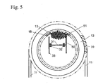
- the drive wheels (33) and (50) are still parallel to one another and are connected by a shaft (31), but the shaft is parallel (31) to the axis of the worm (13).
- Drive wheel (50) is preferably straight cut and meshes with a preferably straight cut gear (51).
Landscapes
- Engineering & Computer Science (AREA)
- Mechanical Engineering (AREA)
- General Engineering & Computer Science (AREA)
- Valve Device For Special Equipments (AREA)
Applications Claiming Priority (4)
| Application Number | Priority Date | Filing Date | Title |
|---|---|---|---|
| US35920302P | 2002-02-22 | 2002-02-22 | |
| US359203P | 2002-02-22 | ||
| US352689 | 2003-01-28 | ||
| US10/352,689 US6622677B2 (en) | 2002-02-22 | 2003-01-28 | Worm gear driven variable cam phaser |
Publications (2)
| Publication Number | Publication Date |
|---|---|
| EP1338761A1 true EP1338761A1 (fr) | 2003-08-27 |
| EP1338761B1 EP1338761B1 (fr) | 2004-12-01 |
Family
ID=27669070
Family Applications (1)
| Application Number | Title | Priority Date | Filing Date |
|---|---|---|---|
| EP03250871A Expired - Lifetime EP1338761B1 (fr) | 2002-02-22 | 2003-02-12 | Engrenage à vis sans fin pour un déphaseur variable |
Country Status (5)
| Country | Link |
|---|---|
| US (1) | US6622677B2 (fr) |
| EP (1) | EP1338761B1 (fr) |
| JP (1) | JP2003269118A (fr) |
| KR (1) | KR20030069883A (fr) |
| DE (1) | DE60300177T2 (fr) |
Cited By (5)
| Publication number | Priority date | Publication date | Assignee | Title |
|---|---|---|---|---|
| EP1801367A1 (fr) * | 2005-12-23 | 2007-06-27 | Delphi Technologies, Inc. | Dispositif variateur de phase |
| EP2009254A1 (fr) * | 2007-06-27 | 2008-12-31 | Delphi Technologies, Inc. | Déphaseur d'arbre à cames |
| EP2025883A1 (fr) * | 2007-07-30 | 2009-02-18 | Delphi Technologies, Inc. | Synchronisateur électromécanique de phase d'arbre à cames doté d'un entraînement par vis sans fin doté d'un actionneur d'entraînement hypoïde |
| WO2010139491A1 (fr) * | 2009-06-02 | 2010-12-09 | Zf Friedrichshafen Ag | Embrayage ou frein dans ou sur une transmission |
| CN102287246A (zh) * | 2010-06-16 | 2011-12-21 | 现代自动车株式会社 | 连续可变气门正时机构 |
Families Citing this family (13)
| Publication number | Priority date | Publication date | Assignee | Title |
|---|---|---|---|---|
| TW575199U (en) * | 2003-06-13 | 2004-02-01 | Young Optics Inc | Multi-axis adjusting apparatus |
| US7258100B2 (en) * | 2004-08-03 | 2007-08-21 | Bruce Pinkston | Internal combustion engine control |
| EP2064417A1 (fr) * | 2006-09-19 | 2009-06-03 | The Timken Company | Appareil de déphasage pour arbre à cames en continu |
| US8025035B2 (en) | 2009-01-09 | 2011-09-27 | Ford Global Technologies, Llc | Mechanical variable camshaft timing device |
| US8042504B2 (en) * | 2009-01-09 | 2011-10-25 | Ford Global Tecnologies, Llc | Adjusting valve timing to deactivate engine cylinders for variable displacement operation |
| US9133735B2 (en) | 2013-03-15 | 2015-09-15 | Kohler Co. | Variable valve timing apparatus and internal combustion engine incorporating the same |
| US10072537B2 (en) | 2015-07-23 | 2018-09-11 | Husco Automotive Holdings Llc | Mechanical cam phasing system and methods |
| JP6676397B2 (ja) * | 2016-02-08 | 2020-04-08 | 株式会社ミクニ | 位相変更ユニット及びバルブタイミング変更装置 |
| CN108331632B (zh) | 2017-01-20 | 2021-12-28 | 胡斯可汽车控股有限公司 | 凸轮定相系统和方法 |
| WO2019134732A1 (fr) * | 2018-01-02 | 2019-07-11 | HELLA GmbH & Co. KGaA | Dispositif d'actionnement pour un appareil de synchronisation d'arbre à cames |
| US10900387B2 (en) | 2018-12-07 | 2021-01-26 | Husco Automotive Holdings Llc | Mechanical cam phasing systems and methods |
| IL301576A (en) | 2020-09-25 | 2023-05-01 | Locudrive Ltd | Toroidal gearbox for slewing mechanisms |
| US12098661B2 (en) | 2022-11-02 | 2024-09-24 | Husco Automotive Holdings Llc | Cam phase actuator control systems and methods |
Citations (9)
| Publication number | Priority date | Publication date | Assignee | Title |
|---|---|---|---|---|
| US1691408A (en) | 1927-03-18 | 1928-11-13 | Palmer Walter Tuttle | Timing device |
| US4517934A (en) | 1979-07-26 | 1985-05-21 | Volkswagenwerk Aktiengesellschaft | Controllable camshaft for a drive, preferably an internal combustion engine |
| US4747375A (en) | 1982-08-31 | 1988-05-31 | Williams John K | Device for controlling the phased displacement of rotating shafts |
| DE4040486A1 (de) * | 1990-06-22 | 1992-01-02 | Schrick Gmbh Dr | Vorrichtung bei verbrennungsmotoren zur drehung der nockenwelle relativ zum nockenwellenantriebsrad |
| US5156119A (en) | 1990-07-31 | 1992-10-20 | Atsugi Unisia Corp. | Valve timing control apparatus |
| US5203291A (en) | 1990-06-28 | 1993-04-20 | Atsugi Unisia Corporation | Valve timing control system for internal combustion engine |
| US5355849A (en) | 1992-07-20 | 1994-10-18 | Miljenko Schiattino | Automatic variator valve overlap or timing and valve section |
| US5680837A (en) | 1996-09-17 | 1997-10-28 | General Motors Corporation | Planetary cam phaser with worm electric actuator |
| US20010020461A1 (en) * | 2000-03-09 | 2001-09-13 | Siegfried Heer | Apparatus for adjusting a camshaft |
Family Cites Families (7)
| Publication number | Priority date | Publication date | Assignee | Title |
|---|---|---|---|---|
| GB8529811D0 (en) * | 1985-12-04 | 1986-01-15 | Stidworthy F M | Variable phase couplings |
| GB9015461D0 (en) * | 1990-07-13 | 1990-08-29 | Phoenix Lancelot | Variable valve timing |
| EP0732483A3 (fr) * | 1995-02-08 | 1997-07-09 | Meta Motoren Energietech | Transmission par engrenage |
| US6378474B1 (en) * | 1999-06-01 | 2002-04-30 | Delphi Technologies, Inc. | Variable value timing mechanism with crank drive |
| JP2001107712A (ja) * | 1999-08-03 | 2001-04-17 | Unisia Jecs Corp | 内燃機関のバルブタイミング制御装置 |
| US6457446B1 (en) | 1999-09-22 | 2002-10-01 | Aimbridge Pty Ltd. | Phase control mechanism |
| AT409030B (de) | 2000-03-09 | 2002-05-27 | Tcg Unitech Ag | Vorrichtung zur verstellung einer nockenwelle |
-
2003
- 2003-01-28 US US10/352,689 patent/US6622677B2/en not_active Expired - Fee Related
- 2003-02-12 EP EP03250871A patent/EP1338761B1/fr not_active Expired - Lifetime
- 2003-02-12 DE DE60300177T patent/DE60300177T2/de not_active Expired - Fee Related
- 2003-02-19 JP JP2003040618A patent/JP2003269118A/ja active Pending
- 2003-02-21 KR KR10-2003-0010878A patent/KR20030069883A/ko not_active Withdrawn
Patent Citations (9)
| Publication number | Priority date | Publication date | Assignee | Title |
|---|---|---|---|---|
| US1691408A (en) | 1927-03-18 | 1928-11-13 | Palmer Walter Tuttle | Timing device |
| US4517934A (en) | 1979-07-26 | 1985-05-21 | Volkswagenwerk Aktiengesellschaft | Controllable camshaft for a drive, preferably an internal combustion engine |
| US4747375A (en) | 1982-08-31 | 1988-05-31 | Williams John K | Device for controlling the phased displacement of rotating shafts |
| DE4040486A1 (de) * | 1990-06-22 | 1992-01-02 | Schrick Gmbh Dr | Vorrichtung bei verbrennungsmotoren zur drehung der nockenwelle relativ zum nockenwellenantriebsrad |
| US5203291A (en) | 1990-06-28 | 1993-04-20 | Atsugi Unisia Corporation | Valve timing control system for internal combustion engine |
| US5156119A (en) | 1990-07-31 | 1992-10-20 | Atsugi Unisia Corp. | Valve timing control apparatus |
| US5355849A (en) | 1992-07-20 | 1994-10-18 | Miljenko Schiattino | Automatic variator valve overlap or timing and valve section |
| US5680837A (en) | 1996-09-17 | 1997-10-28 | General Motors Corporation | Planetary cam phaser with worm electric actuator |
| US20010020461A1 (en) * | 2000-03-09 | 2001-09-13 | Siegfried Heer | Apparatus for adjusting a camshaft |
Cited By (10)
| Publication number | Priority date | Publication date | Assignee | Title |
|---|---|---|---|---|
| EP1801367A1 (fr) * | 2005-12-23 | 2007-06-27 | Delphi Technologies, Inc. | Dispositif variateur de phase |
| EP2009254A1 (fr) * | 2007-06-27 | 2008-12-31 | Delphi Technologies, Inc. | Déphaseur d'arbre à cames |
| EP2025883A1 (fr) * | 2007-07-30 | 2009-02-18 | Delphi Technologies, Inc. | Synchronisateur électromécanique de phase d'arbre à cames doté d'un entraînement par vis sans fin doté d'un actionneur d'entraînement hypoïde |
| US7562645B2 (en) | 2007-07-30 | 2009-07-21 | Delphi Technologies, Inc. | Electromechanical camshaft phaser having a worm gear drive with a hypoid gear actuator |
| WO2010139491A1 (fr) * | 2009-06-02 | 2010-12-09 | Zf Friedrichshafen Ag | Embrayage ou frein dans ou sur une transmission |
| CN102449274A (zh) * | 2009-06-02 | 2012-05-09 | Zf腓德烈斯哈芬股份公司 | 在传动机构里面或上面的离合器或制动器 |
| US8434439B2 (en) | 2009-06-02 | 2013-05-07 | Zf Friedrichshafen Ag | Clutch or brake in or at a gearbox |
| CN102449274B (zh) * | 2009-06-02 | 2014-08-06 | Zf腓德烈斯哈芬股份公司 | 在传动机构里面或上面的离合器或制动器 |
| CN102287246A (zh) * | 2010-06-16 | 2011-12-21 | 现代自动车株式会社 | 连续可变气门正时机构 |
| CN102287246B (zh) * | 2010-06-16 | 2015-05-20 | 现代自动车株式会社 | 连续可变气门正时机构 |
Also Published As
| Publication number | Publication date |
|---|---|
| US20030159670A1 (en) | 2003-08-28 |
| US6622677B2 (en) | 2003-09-23 |
| JP2003269118A (ja) | 2003-09-25 |
| DE60300177T2 (de) | 2005-06-23 |
| DE60300177D1 (de) | 2005-01-05 |
| EP1338761B1 (fr) | 2004-12-01 |
| KR20030069883A (ko) | 2003-08-27 |
Similar Documents
| Publication | Publication Date | Title |
|---|---|---|
| EP1338761B1 (fr) | Engrenage à vis sans fin pour un déphaseur variable | |
| EP0918142B1 (fr) | Dispositif pour le contrôle de la phase angulaire | |
| EP2282020B1 (fr) | Déphaseur d'arbre à cames à commande harmonique avec ressort de rappel | |
| US5417186A (en) | Dual-acting apparatus for variable valve timing and the like | |
| EP2386732B1 (fr) | Mise en phase d'arbre à cames à commande harmonique avec pignon à commande compacte | |
| US7647904B2 (en) | Variable cam phaser apparatus | |
| US8800513B2 (en) | Axially compact coupling for a camshaft phaser actuated by electric motor | |
| WO2009067789A1 (fr) | Arbre à cames concentrique avec entraînement de phase électrique | |
| US20160348759A1 (en) | Split ring carrier with eccentric pin with spring compliance and speed dependence | |
| EP2006501A1 (fr) | Appareil déphaseur à came variable | |
| EP0741235B1 (fr) | Dispositif de commande de phase d'arbre à cames à double sortie | |
| JP2008101609A (ja) | 差動ベベルギヤシステムを有するカムシャフトフェーザー | |
| US7421992B2 (en) | Camshaft | |
| EP0808996A1 (fr) | Dispositif de calage de soupapes pour moteur à combustion interne | |
| JPH07279632A (ja) | 内燃機関のカム軸位相可変装置 | |
| EP1813783B1 (fr) | Appareil de mise en phase d'arbre à cames | |
| US6732688B2 (en) | Valve timing control system for internal combustion engine | |
| JP4419091B2 (ja) | バルブタイミング調整装置 | |
| US6526929B2 (en) | Device for relative angular adjustment between two drive-connected elements rotating at the same rotational speed | |
| EP1801367A1 (fr) | Dispositif variateur de phase | |
| JP2007071059A (ja) | バルブタイミング調整装置 | |
| CN114402122A (zh) | 具有凸轮轴气门相位改变设备的内燃发动机 | |
| JPH11173120A (ja) | 内燃機関の可変動弁装置 | |
| JP2551823Y2 (ja) | 内燃機関のバルブタイミング制御装置 | |
| JP4463211B2 (ja) | バルブタイミング調整装置 |
Legal Events
| Date | Code | Title | Description |
|---|---|---|---|
| PUAI | Public reference made under article 153(3) epc to a published international application that has entered the european phase |
Free format text: ORIGINAL CODE: 0009012 |
|
| AK | Designated contracting states |
Designated state(s): AT BE BG CH CY CZ DE DK EE ES FI FR GB GR HU IE IT LI LU MC NL PT SE SI SK TR |
|
| AX | Request for extension of the european patent |
Extension state: AL LT LV MK RO |
|
| 17P | Request for examination filed |
Effective date: 20031008 |
|
| GRAP | Despatch of communication of intention to grant a patent |
Free format text: ORIGINAL CODE: EPIDOSNIGR1 |
|
| GRAS | Grant fee paid |
Free format text: ORIGINAL CODE: EPIDOSNIGR3 |
|
| AKX | Designation fees paid |
Designated state(s): DE FR GB IT |
|
| GRAA | (expected) grant |
Free format text: ORIGINAL CODE: 0009210 |
|
| AK | Designated contracting states |
Kind code of ref document: B1 Designated state(s): DE FR GB IT |
|
| REG | Reference to a national code |
Ref country code: GB Ref legal event code: FG4D |
|
| REG | Reference to a national code |
Ref country code: IE Ref legal event code: FG4D |
|
| REF | Corresponds to: |
Ref document number: 60300177 Country of ref document: DE Date of ref document: 20050105 Kind code of ref document: P |
|
| PGFP | Annual fee paid to national office [announced via postgrant information from national office to epo] |
Ref country code: FR Payment date: 20050202 Year of fee payment: 3 |
|
| PGFP | Annual fee paid to national office [announced via postgrant information from national office to epo] |
Ref country code: DE Payment date: 20050228 Year of fee payment: 3 |
|
| ET | Fr: translation filed | ||
| PLBE | No opposition filed within time limit |
Free format text: ORIGINAL CODE: 0009261 |
|
| STAA | Information on the status of an ep patent application or granted ep patent |
Free format text: STATUS: NO OPPOSITION FILED WITHIN TIME LIMIT |
|
| 26N | No opposition filed |
Effective date: 20050902 |
|
| PGFP | Annual fee paid to national office [announced via postgrant information from national office to epo] |
Ref country code: IT Payment date: 20060228 Year of fee payment: 4 |
|
| PG25 | Lapsed in a contracting state [announced via postgrant information from national office to epo] |
Ref country code: DE Free format text: LAPSE BECAUSE OF NON-PAYMENT OF DUE FEES Effective date: 20060901 |
|
| REG | Reference to a national code |
Ref country code: FR Ref legal event code: ST Effective date: 20061031 |
|
| GBPC | Gb: european patent ceased through non-payment of renewal fee |
Effective date: 20070212 |
|
| PG25 | Lapsed in a contracting state [announced via postgrant information from national office to epo] |
Ref country code: FR Free format text: LAPSE BECAUSE OF NON-PAYMENT OF DUE FEES Effective date: 20060228 |
|
| PG25 | Lapsed in a contracting state [announced via postgrant information from national office to epo] |
Ref country code: GB Free format text: LAPSE BECAUSE OF NON-PAYMENT OF DUE FEES Effective date: 20070212 |
|
| PG25 | Lapsed in a contracting state [announced via postgrant information from national office to epo] |
Ref country code: IT Free format text: LAPSE BECAUSE OF NON-PAYMENT OF DUE FEES Effective date: 20070212 |