EP2025883A1 - Synchronisateur électromécanique de phase d'arbre à cames doté d'un entraînement par vis sans fin doté d'un actionneur d'entraînement hypoïde - Google Patents
Synchronisateur électromécanique de phase d'arbre à cames doté d'un entraînement par vis sans fin doté d'un actionneur d'entraînement hypoïde Download PDFInfo
- Publication number
- EP2025883A1 EP2025883A1 EP08159370A EP08159370A EP2025883A1 EP 2025883 A1 EP2025883 A1 EP 2025883A1 EP 08159370 A EP08159370 A EP 08159370A EP 08159370 A EP08159370 A EP 08159370A EP 2025883 A1 EP2025883 A1 EP 2025883A1
- Authority
- EP
- European Patent Office
- Prior art keywords
- camshaft
- gear
- pinion gear
- phaser
- rotation
- Prior art date
- Legal status (The legal status is an assumption and is not a legal conclusion. Google has not performed a legal analysis and makes no representation as to the accuracy of the status listed.)
- Withdrawn
Links
- RDYMFSUJUZBWLH-UHFFFAOYSA-N endosulfan Chemical compound C12COS(=O)OCC2C2(Cl)C(Cl)=C(Cl)C1(Cl)C2(Cl)Cl RDYMFSUJUZBWLH-UHFFFAOYSA-N 0.000 title claims abstract description 46
- 230000004044 response Effects 0.000 claims abstract description 4
- 238000002485 combustion reaction Methods 0.000 claims description 6
- 230000008859 change Effects 0.000 claims description 3
- 239000003921 oil Substances 0.000 description 5
- 230000008901 benefit Effects 0.000 description 3
- 230000006835 compression Effects 0.000 description 3
- 238000007906 compression Methods 0.000 description 3
- 239000010705 motor oil Substances 0.000 description 3
- 238000004519 manufacturing process Methods 0.000 description 2
- 238000009987 spinning Methods 0.000 description 2
- 239000002131 composite material Substances 0.000 description 1
- 230000009977 dual effect Effects 0.000 description 1
- 230000000694 effects Effects 0.000 description 1
- 230000010006 flight Effects 0.000 description 1
- 239000000446 fuel Substances 0.000 description 1
- 230000006872 improvement Effects 0.000 description 1
- 239000010687 lubricating oil Substances 0.000 description 1
- 239000000203 mixture Substances 0.000 description 1
- 230000003071 parasitic effect Effects 0.000 description 1
- 230000000750 progressive effect Effects 0.000 description 1
- 230000009467 reduction Effects 0.000 description 1
Images


Classifications
-
- F—MECHANICAL ENGINEERING; LIGHTING; HEATING; WEAPONS; BLASTING
- F01—MACHINES OR ENGINES IN GENERAL; ENGINE PLANTS IN GENERAL; STEAM ENGINES
- F01L—CYCLICALLY OPERATING VALVES FOR MACHINES OR ENGINES
- F01L1/00—Valve-gear or valve arrangements, e.g. lift-valve gear
- F01L1/34—Valve-gear or valve arrangements, e.g. lift-valve gear characterised by the provision of means for changing the timing of the valves without changing the duration of opening and without affecting the magnitude of the valve lift
-
- F—MECHANICAL ENGINEERING; LIGHTING; HEATING; WEAPONS; BLASTING
- F01—MACHINES OR ENGINES IN GENERAL; ENGINE PLANTS IN GENERAL; STEAM ENGINES
- F01L—CYCLICALLY OPERATING VALVES FOR MACHINES OR ENGINES
- F01L1/00—Valve-gear or valve arrangements, e.g. lift-valve gear
- F01L1/34—Valve-gear or valve arrangements, e.g. lift-valve gear characterised by the provision of means for changing the timing of the valves without changing the duration of opening and without affecting the magnitude of the valve lift
- F01L1/344—Valve-gear or valve arrangements, e.g. lift-valve gear characterised by the provision of means for changing the timing of the valves without changing the duration of opening and without affecting the magnitude of the valve lift changing the angular relationship between crankshaft and camshaft, e.g. using helicoidal gear
-
- F—MECHANICAL ENGINEERING; LIGHTING; HEATING; WEAPONS; BLASTING
- F01—MACHINES OR ENGINES IN GENERAL; ENGINE PLANTS IN GENERAL; STEAM ENGINES
- F01L—CYCLICALLY OPERATING VALVES FOR MACHINES OR ENGINES
- F01L1/00—Valve-gear or valve arrangements, e.g. lift-valve gear
- F01L1/34—Valve-gear or valve arrangements, e.g. lift-valve gear characterised by the provision of means for changing the timing of the valves without changing the duration of opening and without affecting the magnitude of the valve lift
- F01L1/344—Valve-gear or valve arrangements, e.g. lift-valve gear characterised by the provision of means for changing the timing of the valves without changing the duration of opening and without affecting the magnitude of the valve lift changing the angular relationship between crankshaft and camshaft, e.g. using helicoidal gear
- F01L1/352—Valve-gear or valve arrangements, e.g. lift-valve gear characterised by the provision of means for changing the timing of the valves without changing the duration of opening and without affecting the magnitude of the valve lift changing the angular relationship between crankshaft and camshaft, e.g. using helicoidal gear using bevel or epicyclic gear
-
- Y—GENERAL TAGGING OF NEW TECHNOLOGICAL DEVELOPMENTS; GENERAL TAGGING OF CROSS-SECTIONAL TECHNOLOGIES SPANNING OVER SEVERAL SECTIONS OF THE IPC; TECHNICAL SUBJECTS COVERED BY FORMER USPC CROSS-REFERENCE ART COLLECTIONS [XRACs] AND DIGESTS
- Y10—TECHNICAL SUBJECTS COVERED BY FORMER USPC
- Y10T—TECHNICAL SUBJECTS COVERED BY FORMER US CLASSIFICATION
- Y10T74/00—Machine element or mechanism
- Y10T74/21—Elements
- Y10T74/2101—Cams
- Y10T74/2102—Adjustable
Definitions
- the present invention relates to camshaft phasers for varying the valve actuation timing of compression valves in an internal combustion engine; more particularly, to an electromechanically-actuated camshaft phaser system having a worm gear drive; and most particularly, to such a phaser system wherein the worm gear is itself driven by a hypoid/ring gear train.
- Camshaft phasers for controllably varying the actuation timing of engine compression valves are well known.
- most prior art camshaft phasers in production by or for engine manufacturers are vane-type phasers having interlocked rotors and stators.
- the phase relationship between the rotor and the stator may be varied by varying the relative oil volume on one side or the other of interlocked vanes via a four-way oil control valve.
- Vane phasers are compact and relatively inexpensive. However, they have difficulty operating rapidly or with precision at times of low oil pressure because phasers typically are powered by parasitic use of pressurized engine lubricating oil. When the engine is idling, or is very hot, or at engine start-up, or combinations of these conditions, engine oil pressure can be very low or substantially non-existent, resulting in poor phasing control and excessive engine emissions.
- an electromechanical camshaft phasing system in accordance with the invention comprises a first pinion gear mounted on the end of an engine camshaft.
- the first pinion gear is engaged by a worm gear mounted on a transverse shaft extending from and journalled in a phaser drive sprocket for a drive chain or a toothed wheel for a toothed drive belt to rotate the camshaft in response to the engine crankshaft.
- the first pinion gear is surrounded by a ring gear driven by an armature or stator of a motor mounted on the engine coaxially of the camshaft and first pinion gear.
- a second pinion gear mounted on the worm gear shaft engages the ring gear such that motor rotation of the ring gear causes rotation of the second pinion gear, worm gear, first pinion gear, and thus the camshaft with respect to the sprocket, thus varying the phase of the camshaft with respect to the crankshaft.
- the present invention is directed to an electromechanical camshaft phaser comprising a phasing worm gear driven by a hypoid/ring gear drive train.
- the worm gear drive is an important improvement on prior art phasers as the worm/pinion gear is essentially self-locking: camshaft torque reversals cannot back-drive the worm gear as happens in oil-actuated prior art vane-type phasers, thus providing good positional stability of the phaser. Further, this arrangement minimizes the number of interfaces from which manufacturing and operational clearances and tolerances may accumulate to create angular lash, which lash results in audible noise. In the present invention, only lash in the worm/pinion gear and lash in the worm gear bearing support can contribute to lash noise. This arrangement further minimizes potential loading of the electric drive motor for the worm gear drive.
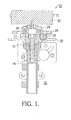
- an electromechanical camshaft phasing system 10 in accordance with the invention comprises a first phasing pinion gear 12 mounted on the end of an engine camshaft 14, for example, by bolt 15.
- First pinion gear 12 is engaged by a worm gear 16 mounted on a transverse shaft journalled by bearings 18 in a phaser drive sprocket 20 that is conventionally rotatable by a timing chain or belt (not shown) driven by a crankshaft (not shown) of an internal combustion engine 22 to which camshaft 14 is mounted, thus driving camshaft 14 in response to the engine crankshaft.
- a ring gear 24 includes a hub 26 keyed to a drive shaft 28 of a driver motor 30, such as for example, an electric motor, mounted on engine 22 coaxially of camshaft 14 and first pinion gear 12.
- a driver motor 30 such as for example, an electric motor
- a second hypoid pinion gear 32 mounted on the shaft of worm gear 16 engages ring gear 24 defining a hypoid reduction gear train 34 such that energizing of the electric motor 30 as shown causes ring gear 24 to rotate about first pinion gear 12 in either rotational direction, depending upon polarity of the current being supplied to motor 30.
- Such rotation of ring gear 24 causes rotation of second pinion gear 32 and hence worm gear 16, causing first pinion gear 12 and camshaft 14 to be rotated with respect to sprocket 20, thus varying the phase of the camshaft with respect to the crankshaft.
- sprocket 20 includes a tang 35 extending radially inwards into a gap 36 in the teeth of first pinion gear 12, defining first and second rotation limiting stops 38,40 for first pinion gear 12.
- second pinion gear 32 is of the known "single-enveloping" type (not shown) wherein the diameter of the hypoid gear flights is progressive to enable greater contact area with the teeth of ring gear 24.
- worm gear 16 is also a known enveloping-type (not shown) gear, either single-enveloping or double-enveloping, again to enable contact with the teeth of first pinion gear 12 over a broad central angle (number of teeth) of gear 12.
- the shaft that supports worm gear 16 and second pinion gear 32 may be fixed in sprocket 20 rather than journalled for rotation, and worm gear 16 and second pinion gear 32 may be mounted on a sleeve that is rotatable upon the shaft, to equal effect as in the first embodiment described above.
- the overriding consideration is simply that worm gear 16 be rotationally coupled to second pinion gear 32, whatever the supporting structure.
- an electromechanical camshaft phaser 10 in accordance with the invention may be readily incorporated on a first camshaft 14 in a dual camshaft engine 122 wherein a second camshaft 114 is provided with either a similar electromechanical phaser or with a conventional vane-type phaser 110.
- the sprockets 20,120 of the phasers may be driven in time by a common drive chain (not shown).
- the second camshaft may have a phaser of any type or no phaser, and the electromechanical phaser may be applied to intake, exhaust or on both camshafts, or to a single camshaft engine wherein the camshaft drives intake and exhaust valves.
- the position of the second pinion gear 32, worm gear 16, and teeth on first pinion gear 12 can be changed to the opposite side of the phaser axis to change the default position (advance or retard) that obtains if motor 30 is used for braking.
- An electrically driven phaser in accordance with the invention may be applied to either an intake or an exhaust camshaft. It is most advantageous to apply the invention to the intake camshaft, as a major advantage is to enable repositioning of the intake cam during engine cranking (prior to any oil pressure being available) to obtain the optimal cam timing based on the temperature conditions of the engine. Once the engine fires, the cam timing can also be adjusted as needed during the first couple of seconds of engine run time to minimize emissions. This is a significant advantage over engines equipped with prior art oil-actuated phasers because a large portion of engine emissions occurs in the first few seconds of engine run time when the fuel/air mixture is quite rich and combustion is not yet running smoothly.
- the electric motor 30 can be operated in a motor mode, spinning the ring gear 24 faster (ahead of) than the rotational speed of the pinion gear 12, or in a generator mode (braking mode) spinning ring gear 24 slower (behind) than the rotational speed of pinion gear 12.
- the hand (right or left hand) of the gearing can be reversed as suitable for either intake camshaft or exhaust camshaft applications so as to preferably move the phaser either towards advance or towards retard timing.
Landscapes
- Engineering & Computer Science (AREA)
- Mechanical Engineering (AREA)
- General Engineering & Computer Science (AREA)
- Valve Device For Special Equipments (AREA)
Applications Claiming Priority (1)
| Application Number | Priority Date | Filing Date | Title |
|---|---|---|---|
| US11/881,915 US7562645B2 (en) | 2007-07-30 | 2007-07-30 | Electromechanical camshaft phaser having a worm gear drive with a hypoid gear actuator |
Publications (1)
| Publication Number | Publication Date |
|---|---|
| EP2025883A1 true EP2025883A1 (fr) | 2009-02-18 |
Family
ID=40083657
Family Applications (1)
| Application Number | Title | Priority Date | Filing Date |
|---|---|---|---|
| EP08159370A Withdrawn EP2025883A1 (fr) | 2007-07-30 | 2008-06-30 | Synchronisateur électromécanique de phase d'arbre à cames doté d'un entraînement par vis sans fin doté d'un actionneur d'entraînement hypoïde |
Country Status (2)
| Country | Link |
|---|---|
| US (1) | US7562645B2 (fr) |
| EP (1) | EP2025883A1 (fr) |
Cited By (1)
| Publication number | Priority date | Publication date | Assignee | Title |
|---|---|---|---|---|
| EP2617954A1 (fr) * | 2011-12-29 | 2013-07-24 | Robert Bosch Gmbh | Dispositif de couplage destiné à la fabrication d'une liaison active entre un arbre à came et un arbre à manivelle d'un moteur à combustion interne, procédé de fonctionnement du dispositif de couplage ainsi que commande de soupape d'un moteur à combustion interne |
Families Citing this family (9)
| Publication number | Priority date | Publication date | Assignee | Title |
|---|---|---|---|---|
| KR101209725B1 (ko) * | 2010-06-16 | 2012-12-07 | 현대자동차주식회사 | 연속 가변 밸브 타이밍 장치 |
| US8682564B2 (en) * | 2010-08-30 | 2014-03-25 | Delphi Technologies, Inc. | Camshaft position sensing in engines with electric variable cam phasers |
| KR101172332B1 (ko) * | 2010-12-06 | 2012-08-07 | 현대자동차주식회사 | 가변 밸브 타이밍 장치 |
| WO2014092973A1 (fr) * | 2012-12-10 | 2014-06-19 | Borgwarner Inc. | Dispositif de mise en phase de cames planétaire simple entraîné par un moteur électrique |
| DE102014009188A1 (de) * | 2014-06-12 | 2015-12-17 | Daimler Ag | Verfahren zur Verstellung einer Phasenlage einer Nockenwelle |
| CN104233592B (zh) * | 2014-10-13 | 2016-05-11 | 湖州现代纺织机械有限公司 | 一种凸轮调节机构 |
| DE102016213797A1 (de) * | 2016-07-27 | 2017-07-20 | Schaeffler Technologies AG & Co. KG | Nockenwellenversteller |
| US10415670B2 (en) * | 2017-05-09 | 2019-09-17 | Astronova, Inc. | Worm drive |
| IL301576A (en) * | 2020-09-25 | 2023-05-01 | Locudrive Ltd | Toroidal gearbox for slewing mechanisms |
Citations (6)
| Publication number | Priority date | Publication date | Assignee | Title |
|---|---|---|---|---|
| DE4040486A1 (de) * | 1990-06-22 | 1992-01-02 | Schrick Gmbh Dr | Vorrichtung bei verbrennungsmotoren zur drehung der nockenwelle relativ zum nockenwellenantriebsrad |
| US5156119A (en) * | 1990-07-31 | 1992-10-20 | Atsugi Unisia Corp. | Valve timing control apparatus |
| DE19951392A1 (de) * | 1999-10-26 | 2001-05-03 | Schaeffler Waelzlager Ohg | Vorrichtung zur drehfesten Kopplung und zur Veränderung der relativen Drehlage zweier koaxial um eine Drehachse drehbarer Gehäuse |
| EP1136658A2 (fr) * | 2000-03-09 | 2001-09-26 | TCG UNITECH Aktiengesellschaft | Dispositif de réglage du calage d'un arbre à cames |
| EP1338761A1 (fr) * | 2002-02-22 | 2003-08-27 | BorgWarner Inc. | Engrenage à vis sans fin pour un déphaseur variable |
| EP1801367A1 (fr) * | 2005-12-23 | 2007-06-27 | Delphi Technologies, Inc. | Dispositif variateur de phase |
Family Cites Families (1)
| Publication number | Priority date | Publication date | Assignee | Title |
|---|---|---|---|---|
| US5680837A (en) * | 1996-09-17 | 1997-10-28 | General Motors Corporation | Planetary cam phaser with worm electric actuator |
-
2007
- 2007-07-30 US US11/881,915 patent/US7562645B2/en not_active Expired - Fee Related
-
2008
- 2008-06-30 EP EP08159370A patent/EP2025883A1/fr not_active Withdrawn
Patent Citations (6)
| Publication number | Priority date | Publication date | Assignee | Title |
|---|---|---|---|---|
| DE4040486A1 (de) * | 1990-06-22 | 1992-01-02 | Schrick Gmbh Dr | Vorrichtung bei verbrennungsmotoren zur drehung der nockenwelle relativ zum nockenwellenantriebsrad |
| US5156119A (en) * | 1990-07-31 | 1992-10-20 | Atsugi Unisia Corp. | Valve timing control apparatus |
| DE19951392A1 (de) * | 1999-10-26 | 2001-05-03 | Schaeffler Waelzlager Ohg | Vorrichtung zur drehfesten Kopplung und zur Veränderung der relativen Drehlage zweier koaxial um eine Drehachse drehbarer Gehäuse |
| EP1136658A2 (fr) * | 2000-03-09 | 2001-09-26 | TCG UNITECH Aktiengesellschaft | Dispositif de réglage du calage d'un arbre à cames |
| EP1338761A1 (fr) * | 2002-02-22 | 2003-08-27 | BorgWarner Inc. | Engrenage à vis sans fin pour un déphaseur variable |
| EP1801367A1 (fr) * | 2005-12-23 | 2007-06-27 | Delphi Technologies, Inc. | Dispositif variateur de phase |
Cited By (1)
| Publication number | Priority date | Publication date | Assignee | Title |
|---|---|---|---|---|
| EP2617954A1 (fr) * | 2011-12-29 | 2013-07-24 | Robert Bosch Gmbh | Dispositif de couplage destiné à la fabrication d'une liaison active entre un arbre à came et un arbre à manivelle d'un moteur à combustion interne, procédé de fonctionnement du dispositif de couplage ainsi que commande de soupape d'un moteur à combustion interne |
Also Published As
| Publication number | Publication date |
|---|---|
| US20090031974A1 (en) | 2009-02-05 |
| US7562645B2 (en) | 2009-07-21 |
Similar Documents
| Publication | Publication Date | Title |
|---|---|---|
| US7562645B2 (en) | Electromechanical camshaft phaser having a worm gear drive with a hypoid gear actuator | |
| US7421990B2 (en) | Harmonic drive camshaft phaser | |
| US8682564B2 (en) | Camshaft position sensing in engines with electric variable cam phasers | |
| EP2282020B1 (fr) | Déphaseur d'arbre à cames à commande harmonique avec ressort de rappel | |
| US7647904B2 (en) | Variable cam phaser apparatus | |
| JP4233521B2 (ja) | 電気的な駆動部を備えたカム軸調節装置 | |
| US8622037B2 (en) | Harmonic drive camshaft phaser with a compact drive sprocket | |
| CN102439265B (zh) | 用于内燃机的移相器组件 | |
| WO2009067789A1 (fr) | Arbre à cames concentrique avec entraînement de phase électrique | |
| US20090120388A1 (en) | Electro-hydraulic hybrid camshaft phaser | |
| US8322318B2 (en) | Harmonic drive camshaft phaser with phase authority stops | |
| JP2005532503A (ja) | 電気的な駆動部を備えたカム軸調節装置 | |
| JP5391461B2 (ja) | カムシャフトユニット | |
| JP2007224865A (ja) | バルブタイミング調整装置 | |
| JP4552902B2 (ja) | バルブタイミング調整装置 | |
| EP2194241A1 (fr) | Déphaseur à came variable | |
| JP2002227623A (ja) | 内燃機関のバルブタイミング制御装置 | |
| EP1813783B1 (fr) | Appareil de mise en phase d'arbre à cames | |
| KR20110104009A (ko) | 소형 전기 캠 페이저 | |
| EP2009254A1 (fr) | Déphaseur d'arbre à cames | |
| EP1801367A1 (fr) | Dispositif variateur de phase | |
| JP4678537B2 (ja) | バルブタイミング調整装置 | |
| EP2017436A1 (fr) | Appareil déphaseur à came variable | |
| WO2020137782A1 (fr) | Dispositif de réglage de calage de distribution | |
| JP2009062895A (ja) | バルブタイミング調整装置 |
Legal Events
| Date | Code | Title | Description |
|---|---|---|---|
| PUAI | Public reference made under article 153(3) epc to a published international application that has entered the european phase |
Free format text: ORIGINAL CODE: 0009012 |
|
| AK | Designated contracting states |
Kind code of ref document: A1 Designated state(s): AT BE BG CH CY CZ DE DK EE ES FI FR GB GR HR HU IE IS IT LI LT LU LV MC MT NL NO PL PT RO SE SI SK TR |
|
| AX | Request for extension of the european patent |
Extension state: AL BA MK RS |
|
| AKX | Designation fees paid | ||
| REG | Reference to a national code |
Ref country code: DE Ref legal event code: 8566 |
|
| STAA | Information on the status of an ep patent application or granted ep patent |
Free format text: STATUS: THE APPLICATION IS DEEMED TO BE WITHDRAWN |
|
| 18D | Application deemed to be withdrawn |
Effective date: 20090819 |