EP1338779A2 - Apparat für die Steuerung eines Verbrennungsmotors - Google Patents
Apparat für die Steuerung eines Verbrennungsmotors Download PDFInfo
- Publication number
- EP1338779A2 EP1338779A2 EP03002737A EP03002737A EP1338779A2 EP 1338779 A2 EP1338779 A2 EP 1338779A2 EP 03002737 A EP03002737 A EP 03002737A EP 03002737 A EP03002737 A EP 03002737A EP 1338779 A2 EP1338779 A2 EP 1338779A2
- Authority
- EP
- European Patent Office
- Prior art keywords
- signal
- cylinder
- cam
- crank
- determining processing
- Prior art date
- Legal status (The legal status is an assumption and is not a legal conclusion. Google has not performed a legal analysis and makes no representation as to the accuracy of the status listed.)
- Granted
Links
Images


Classifications
-
- F—MECHANICAL ENGINEERING; LIGHTING; HEATING; WEAPONS; BLASTING
- F02—COMBUSTION ENGINES; HOT-GAS OR COMBUSTION-PRODUCT ENGINE PLANTS
- F02D—CONTROLLING COMBUSTION ENGINES
- F02D41/00—Electrical control of supply of combustible mixture or its constituents
- F02D41/009—Electrical control of supply of combustible mixture or its constituents using means for generating position or synchronisation signals
-
- F—MECHANICAL ENGINEERING; LIGHTING; HEATING; WEAPONS; BLASTING
- F02—COMBUSTION ENGINES; HOT-GAS OR COMBUSTION-PRODUCT ENGINE PLANTS
- F02D—CONTROLLING COMBUSTION ENGINES
- F02D41/00—Electrical control of supply of combustible mixture or its constituents
- F02D41/02—Circuit arrangements for generating control signals
- F02D41/04—Introducing corrections for particular operating conditions
- F02D41/06—Introducing corrections for particular operating conditions for engine starting or warming up
- F02D41/062—Introducing corrections for particular operating conditions for engine starting or warming up for starting
-
- F—MECHANICAL ENGINEERING; LIGHTING; HEATING; WEAPONS; BLASTING
- F02—COMBUSTION ENGINES; HOT-GAS OR COMBUSTION-PRODUCT ENGINE PLANTS
- F02D—CONTROLLING COMBUSTION ENGINES
- F02D41/00—Electrical control of supply of combustible mixture or its constituents
- F02D41/22—Safety or indicating devices for abnormal conditions
- F02D41/222—Safety or indicating devices for abnormal conditions relating to the failure of sensors or parameter detection devices
-
- F—MECHANICAL ENGINEERING; LIGHTING; HEATING; WEAPONS; BLASTING
- F02—COMBUSTION ENGINES; HOT-GAS OR COMBUSTION-PRODUCT ENGINE PLANTS
- F02D—CONTROLLING COMBUSTION ENGINES
- F02D41/00—Electrical control of supply of combustible mixture or its constituents
- F02D41/009—Electrical control of supply of combustible mixture or its constituents using means for generating position or synchronisation signals
- F02D2041/0092—Synchronisation of the cylinders at engine start
-
- F—MECHANICAL ENGINEERING; LIGHTING; HEATING; WEAPONS; BLASTING
- F02—COMBUSTION ENGINES; HOT-GAS OR COMBUSTION-PRODUCT ENGINE PLANTS
- F02D—CONTROLLING COMBUSTION ENGINES
- F02D41/00—Electrical control of supply of combustible mixture or its constituents
- F02D41/02—Circuit arrangements for generating control signals
- F02D41/14—Introducing closed-loop corrections
- F02D41/1401—Introducing closed-loop corrections characterised by the control or regulation method
- F02D41/1402—Adaptive control
Definitions
- the present invention relates to an engine control apparatus for executing a cylinder determining processing of a multi-cylinder engine by using a crank sensor and a cam sensor.
- a cylinder determining and detecting apparatus for an internal combustion engine disclosed in JP-A-5-133268 is known in the art. According to the apparatus disclosed in the document, it discloses a method for detecting rotation of a crankshaft and a camshaft of a four-cycle engine by a crank sensor and a cam sensor respectively, and for executing a cylinder determining processing on the basis of the detecting results of the sensors.
- the crank sensor has a rotor of which outside is provided with protrusions in even intervals and with an absence tooth portion which is formed by removing a part of the protrusions.
- the can sensor has a rotor of which outside is provided with protrusions in even intervals and with an auxiliary tooth in one location.
- the absence tooth portion and the auxiliary tooth correspond to a predetermined angular position, e.g., top dead center, of a predetermined particular cylinder. Therefore, it is possible to determine the cylinder based on the crank sensor alone. It is also possible to determine the cylinder based on the cam sensor alone.
- a method for executing a cylinder determining processing on the basis of a combination of the detected signals of both sensors is also proposed.
- a detection of the absence tooth of the crank sensor is executed every rotation of the crankshaft, that is every 360°CA.
- the absence tooth is detected at predetermined angular position, e.g., top dead center, of two cylinders. Therefore, in case of that the cylinder determining processing is temporarily suspended due to abnormalities of both the crank sensor and the cam sensor while the engine is operated, even if only the crank sensor is recovered to normal, it is impossible to determine the particular one of the cylinders based on the cylinder determining processing using the crank sensor alone.
- the present invention was accomplished in consideration of the above-mentioned circumstances, therefore it is an object of the present invention to provide an engine control apparatus that is capable of executing the cylinder determining processing in an appropriate manner, and resolving the above-mentioned problems due to an incorrect cylinder determination.
- a crank sensor detects rotation of a crankshafts, and outputs a crank signal including angle indicating parts and reference position indicating parts.
- a cam sensor detects rotation of a camshaft, and outputs a cam signal including angle indicating parts and reference position indicating parts. It is important that the apparatus is provided with a first cylinder determining means and a second cylinder determining means as means for determining cylinder. The cylinder determination is carried out on the basis of the crank signal, and the cylinder determining processing is carried out on the basis of the cam signal too.
- a sensor signal abnormality detecting means detects an abnormality of the crank signal and the cam signal respectively.
- a cylinder determination controlling means prohibits the cylinder determining processing of the first cylinder determining means when both the crank signal and the cam signal become abnormal while operating the engine. Then, the cylinder determination controlling means withdraws the prohibition of the cylinder determining processing on the condition that the cam signal is recovered normal.
- the cylinder determining processing may be resumed if the cam signal is recovered to normal. In this case, even if the crank signal is recovered earlier, the cylinder determining processing using the crank signal alone is still prohibited. If the crank signal is still abnormal when the cam signal is recovered, the cylinder determining processing is executed by using the cam signal alone. There is a possibility to make an incorrect cylinder determination on the basis of the crank signal alone. However, the incorrect cylinder determination can be prevented since the cam signal enables to determine one particular cylinder by using itself alone. As a result, by executing the cylinder determining processing of the engine in an appropriate manner, it is possible to resolve several problems due to the incorrect cylinder determination.
- the cylinder determining processing may be prohibited on the condition that an engine speed is higher than a predetermined speed in addition to the condition that both the crank signal and the cam signal are abnormal.
- a result of the cylinder determining processing may be inverted oppositely when it is not detected to increase an engine speed by monitoring change of the engine speed after a completion of the cylinder determining processing of the first cylinder determining means when starting the engine.
- the starting of the engine even if the cylinder is incorrectly determined, it merely makes it difficult to start the engine, and the engine is not damaged. It is possible to determine the cylinder correctly by just inverting the result of the cylinder determination in a relationship of a front side and a backside.
- two cylinders distanced by 360°CA are considered as the cylinders in the front side and the backside.
- the prohibition of the cylinder determining processing caused by the cylinder determination controlling means may be withdrawn when the engine stalls. In this case, since a restarting operation might be carried out if an engine stall occurs, therefore it is possible to execute the cylinder determining processing using the crank signal alone even if the cam signal is continuously abnormal.
- the cylinder determining processing may be executed by referring reference position detecting data of the cam signal in response to the detection of the reference position of the crank signal.
- the results of the cylinder determining processing are stored as a history at every time of the cylinder determining processing. Then, the result of the cylinder determining processing is examined whether or not it is correct on the basis of the history characterized by a plurality of results of succeeded cylinder determining processing.
- the cylinder determining processing on the basis of a combination of the crank signal and the cam signal, there is a possibility to make an incorrect cylinder determination if a pulse is incorrectly recognized due to a noise or the like. On the contrary, according to the invention, it is possible to achieve an anti-noise measure.
- the prohibition of the cylinder determining processing may be withdrawn on the condition that an engine speed is decreased to a predetermined speed after both the crank signal and the cam signal became abnormal.
- the crankshaft and the camshaft are mechanically coupled and rotate in keeping an angular synchronousness, an angular position between them might be shifted in a high-speed rotation.
- a phase difference may appear between the crank signal and the cam signal at the high-speed rotation.
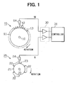
- a disk shaped NE rotor 11 is fixed on a crankshaft 10 of the engine.
- a plurality of protrusions 12 are formed on an outer periphery of the NE rotor 11 in every predetermined rotation angle intervals of the crankshaft 10, that is 15°CA in the embodiment.
- An absence tooth portion 13 is formed by removing one tooth out of the plurality of protrusions 12 at the vicinity of the particular cylinder, e.g., the vicinities of the top dead center, TDC, of the first cylinder and the sixth cylinder. Therefore, total 23, twenty-three, of the protrusions 12 are formed on the NE rotor 11.
- An electromagnetic pickup coil 14 is disposed adjacent to the outer periphery of the NE rotor 11.
- the electromagnetic pickup coil 14 generates signal in response to every passing of the protrusions 12.
- the detected signal of the electromagnetic pickup coil 14 is inputted in a waveform shaping circuit 30 and shaped into pulses.
- the NE rotor 11 and the electromagnetic pickup coil 14 provide a crank sensor 15.
- a camshaft 20 synchronously rotates with the crankshaft 10 of the engine, and makes one rotation during the crankshaft 10 rotates twice.
- a disk shaped cam rotor 21 is fixed on the camshaft 20.
- Protrusions 22 for the number of cylinders are formed on an outer periphery of the cam rotor 21 in even intervals.
- the embodiment exemplifies the six-cylinder engine, therefore, the protrusions 22 are formed on the outer periphery of the cam rotor 21 in every 60 degrees, that is 120°CA of crank angle.
- each of the protrusions 22 is formed on a position 45°CA before TDC of each cylinder of the engine.
- an auxiliary tooth 23 is formed on the outer periphery of the cam rotor 21 on just before the protrusion corresponding to the first cylinder.
- the auxiliary tooth 23 is formed on a position 75°CA before TDC of the first cylinder.
- An electromagnetic pickup coil 24 is disposed adjacent to the outer periphery of the cam rotor 21.
- the electromagnetic pickup coil 24 generates signal in response to every passing of the protrusions 22 and the auxiliary tooth 23.
- the detected signal of the electromagnetic pickup coil 24 is inputted in a waveform shaping circuit 30 and shaped into pulses.
- the cam rotor 21 and the electromagnetic pickup coil 24 provide a cam sensor 25.
- a microcomputer, hereinafter referred to as a controller, 31 is configured as a well-known logic circuit having a CPU, ROM, RAM and the like.
- the controller 31 executes an engine speed computing processing and a cylinder determining processing on the basis of the detected signal, crank signal, of the crank sensor 15 and the detected signal, cam signal, of the cam sensor 25 which are inputted via the waveform shaping circuit 30.
- the controller 31 executes several controls such as fuel injection, injection timing, injection pressure, on the basis of the results of the cylinder determining processing and the engine speed computing processing.
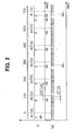
- FIG. 2 is a time chart showing signal shapes of the crank signal and the cam signal.
- a firing order of the cylinders is 1-5-3-6-2-4. Therefore, the TDC of the first cylinder #1TDC and the TDC of the sixth cylinder #6TDC are arranged in a relationship of a front side and a backside which are distanced by just 360°CA.
- the crank signal is shown as a pulse train with 15°CA intervals, and has absence tooth parts 13 just before the #1TDC and just before the #6TDC.
- the appearance of the absence tooth parts 13 are used for detecting the #1TDC and the #6TDC.
- the absence tooth corresponding to the #1TDC is assumed as a front side absence tooth
- the absence tooth corresponding to the #6TDC is assumed as a backside absence tooth.
- the cam signal is shown as a pulse train with 120°CA intervals, and has the auxiliary tooth pulse corresponding to the auxiliary tooth 23.
- the auxiliary tooth pulse appears just before a cam pulse corresponding to the #1TDC, that is shown as G0 in the drawing.
- the appearance of the auxiliary tooth pulse is once within 720°CA. Therefore, by detecting an existence or absence of the auxiliary tooth pulse within a predetermined period just before a detection of the absence tooth of the crank signal, e.g., 60°CA before NE0 in the drawing, it is possible to determine whether the #1TDC, the front absence tooth, or the #6TDC, the backside absence tooth.
- the pulse train part with 15°CA intervals in the crank signal corresponds to an angle indicating part
- the absence tooth part corresponds to a reference position indicating part
- the pulse train part with 120°CA intervals in the cam signal corresponds to an angle indicating part
- the auxiliary tooth pulse corresponds to a reference position indicating part.
- the settings such as the pulse intervals of 15°CA and 120°CA may be modified.
- FIG. 3 is a flowchart showing a crank signal interrupt routine which is started in response to a rising edge of the crank signal by the controller 31.
- the routine executes the cylinder determining processing using the crank signal alone.
- step 103 it is determined that whether or not the pulse interval TNEi is equal to or smaller than 3 / 2 ⁇ TNEi-1. If a determination is YES, the routine proceeds to step 104, and increments NEi.
- step 106 it is determined that whether or not the cylinder determining processing using the crank signal alone is prohibited at the present on the basis of a flag showing a prohibition of crank only determination.
- step 107 the cylinder determining processing using the crank signal alone is executed.
- the cylinder determining processing using the crank signal is executed.
- it is impossible to determine whether it corresponds to the #1TDC, the front side absence tooth, or the #6TDC, the backside absence tooth.
- it is determined as the #1TDC, the front side absence tooth, in an assumption manner.
- the #1TDC, the front side absence tooth, and the #6TDC, the backside absence tooth are alternately determined in response to later every detection of the reference position.
- step 108 it is determined whether or not the engine speed exceeds 400 rpm within two, 2, seconds after a completion of the cylinder determining processing.
- the routine is finished.
- NO in step 108 it is assumed that the result of the cylinder determining processing in step 107 was incorrect and the engine starting was not succeeded, then the routine proceeds to step 109.
- step 109 the front side or the backside of the result of the cylinder determining processing is inverted. That is, if the result was that the #1TDC, the front side absence tooth, was determined, the result is inverted to the #6TDC, the backside absence tooth.
- FIG. 4 is a flowchart showing a routine of a cam signal interruption processing which is started by the controller 31 in response to a rising edge of the cam signal.
- the routine executes the cylinder determining processing using the cam signal alone.
- step 203 it is determined that whether or not the pulse interval TGi is equal to or smaller than 1 / 2 x TGi-1. If a determination is YES, the routine proceeds to step 204, and increments a cam pulse number Gi.
- step 203 If the determination is NO in step 203, it is assumed that it is reached to the reference position, the cam pulse just after the auxiliary tooth pulse, at the present cam signal interruption, the cam pulse number Gi is set G0 in step 205. After that, in step 206, the cylinder determining processing using the cam signal alone is executed. In this case, a detection of the reference position of the cam signal is determined as the #1TDC, the front side absence tooth. In conclusion, in step 207, a flag indicative of a prohibition of a crank only determination is cleared.
- FIG. 5 is a flowchart showing a routine of a processing for detecting abnormalities of the crank signal and the cam signal.
- the routine is cyclically executed every predetermined period, e.g., four, 4, milliseconds, by the controller 31.
- step 301 it is determined that whether or not an edge, e.g., a rising edge, of the crank signal appears. If the edge has been detected just before, the routine proceeds to step 302, and clears a crank signal abnormality monitoring counter CDGNE to 0. In the following step 303, it is determined that the crank signal is normal.
- edge e.g., a rising edge
- step 304 If the edge has not been detected, the routine proceeds to step 304, and increments the abnormality monitoring counter CDGNE.
- step 305 it is determined whether or not the value of CDGNE becomes equal to or greater than a predetermined value THNE.
- the result of YES in step 305 indicates that no crank edge is detected during a predetermined period, that is the lost of inputting of the crank signal. In this case, the routine proceeds to step 306, and determines that the crank signal is abnormal.
- step 307 it is determined that whether or not an edge, e.g., a rising edge, of the can signal appears. If the edge has been detected just before, the routine proceeds to step 308, and clears a cam signal abnormality monitoring counter CDGG to 0. In the following step 309, it is determined that the cam signal is normal.
- edge e.g., a rising edge
- step 310 If the edge has not been detected, the routine proceeds to step 310, and increments the cam signal abnormality monitoring counter CDGG.
- step 311 it is determined whether or not the value of CDGG becomes equal to or greater than a predetermined value THG.
- the result of YES in step 311 indicates that no cam edge is detected during the predetermined period, that is the lost of inputting of the cam signal. In this case, the routine proceeds to step 312, and determines that the cam signal is abnormal.
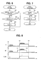
- FIG. 6 is a flowchart showing a processing for setting the flag indicative of the prohibition of the crank only determination.
- the processing is executed as a periodical processing with predetermined cycle by the controller 31.
- step 401 it is determined that whether or not the engine speed is equal to or higher than a value, e.g., 1000 rpm. Thereby, it is determined that whether or not the engine rises higher than a starting condition and is running at a certain level of high-speed range.
- step 402 it is determined that whether or not both the crank signal and the cam signal are abnormal.
- step 207 in FIG. 4 besides the flag may be cleared in response to the engine stall. That is, in the engine stall processing shown in FIG. 7, it is determined that whether or not the engine stalls, step 501, and the flag is cleared to 0 in response to the engine stall, step 502.
- the prohibition of the cylinder determining processing may be withdrawn on the condition that the engine speed is decreased to a predetermined speed after both the crank signal and the cam signal became abnormal.
- FIG. 8 is a time chart showing detail of operation of the above-described processing.
- any cylinder determining processing is not executed, and the controls such as the fuel injection are also suspended.
- the engine is operated in a condition at certain level of high-speed, the engine keeps running due to its inertial rotation. Therefore, it is possible to operate the engine continuously after the timing t4.
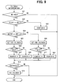
- FIG. 9 shows a cylinder determining process.
- the processing is executed in an interrupt manner in response to the rising edge of the crank signal by the controller 31.
- the processing is designed to prevent an incorrect cylinder determination due to a noise, and counts a history counter at every determination of the cylinder determining processing and executes a final cylinder determining processing based on the history counter value.
- step 601 it is determined that whether the crank pulse number NEi is equal to NE0 indicating the reference position. In case of YES, the routine proceeds to step 602. After that, in step 602, it is determined whether or not one inputting of the cam pulse is detected between NEi and NEi-1. If the result is NO, the routine proceeds to step 603, and clears the history counter.
- step 604 it is determined that whether or not an auxiliary tooth cam pulse is inputted between NEi-1 and NEi-2. If step 604 was YES, the routine proceeds to step 605, and temporarily set the first cylinder, #1TDC, as the present cylinder. In the following steps 606-608, if the last time was the sixth cylinder, #6TDC, the history counter is incremented, and if the last time was not the sixth cylinder, #6TDC, the history counter is cleared.
- step 604 the routine proceeds to step 609, and temporarily set the sixth cylinder, #6TDC, as the present cylinder.
- step 609 the routine proceeds to step 609, and temporarily set the sixth cylinder, #6TDC, as the present cylinder.
- steps 610-612 if the last time was the first cylinder, #1TDC, the history counter is incremented, and if the last time was not the first cylinder, #1TDC, the history counter is cleared.
- step 613 it is determined that whether or not the history counter is equal to or higher than a predetermined value, that is two in this embodiment. In case of YES, the routine proceeds to step 614, and finally fixes the temporary set cylinder.
- the present invention may be implemented in the following manner.
- a phase difference between the crank signal and the cam signal may be generated at a high-speed.
- the prohibition of the cylinder determining processing is withdrawn while the phase difference continues, there may be an incorrect cylinder determination too. Therefore, in case of becoming the prohibition of the cylinder determining processing due to becoming both the crank signal and the cam signal abnormal, the prohibition of the cylinder determining processing is withdrawn on condition that the engine speed is decreased to a predetermined speed, e.g., about 1000 rpm. Thereby, a reliability of the cylinder determining processing is improved.
- the method for detecting the abnormalities of the crank signal and the cam signal may be replaced with another method other than the described method.
- a system that monitors an existence and an absence of edges of the signals each other at the crank signal interruption and the cam signal interruption may be used.
- the history counter is held 0 when the cam inputting corresponding to the crank absence tooth portion is not detected, or a particular cylinder temporary setting of the same cylinder is succeeded.
- the history of the occurrence of abnormality may be stored by incrementing the abnormality counter.
- a storing of a diagnosis code, malfunction information, or a warning for a driver on the basis of the abnormality counter may be executed.
- crank signal and the cam signal are not limited in the embodiment, and they may be modified freely on the condition that each has the angle indicating part and the reference position indicating part.
- present invention may be applied for a four-cycle gasoline engine.
Landscapes
- Engineering & Computer Science (AREA)
- Chemical & Material Sciences (AREA)
- Combustion & Propulsion (AREA)
- Mechanical Engineering (AREA)
- General Engineering & Computer Science (AREA)
- Combined Controls Of Internal Combustion Engines (AREA)
Applications Claiming Priority (2)
| Application Number | Priority Date | Filing Date | Title |
|---|---|---|---|
| JP2002049948A JP4151279B2 (ja) | 2002-02-26 | 2002-02-26 | エンジン制御装置 |
| JP2002049948 | 2002-02-26 |
Publications (3)
| Publication Number | Publication Date |
|---|---|
| EP1338779A2 true EP1338779A2 (de) | 2003-08-27 |
| EP1338779A3 EP1338779A3 (de) | 2006-09-27 |
| EP1338779B1 EP1338779B1 (de) | 2008-10-22 |
Family
ID=27655490
Family Applications (1)
| Application Number | Title | Priority Date | Filing Date |
|---|---|---|---|
| EP03002737A Expired - Lifetime EP1338779B1 (de) | 2002-02-26 | 2003-02-06 | Apparat für die Steuerung eines Verbrennungsmotors |
Country Status (5)
| Country | Link |
|---|---|
| US (1) | US6775611B2 (de) |
| EP (1) | EP1338779B1 (de) |
| JP (1) | JP4151279B2 (de) |
| CN (1) | CN100501146C (de) |
| DE (1) | DE60324214D1 (de) |
Cited By (2)
| Publication number | Priority date | Publication date | Assignee | Title |
|---|---|---|---|---|
| EP1849982A3 (de) * | 2006-04-24 | 2009-01-14 | Denso Corporation | Motorsteuervorrichtung und dazugehöriges Motorsteuerverfahren |
| CN115355096A (zh) * | 2022-08-03 | 2022-11-18 | 中车大连机车车辆有限公司 | 一种发动机快速启动同步控制方法 |
Families Citing this family (31)
| Publication number | Priority date | Publication date | Assignee | Title |
|---|---|---|---|---|
| US7031792B2 (en) * | 2001-04-04 | 2006-04-18 | Tokyo Electron Limited | Processing apparatus and information storage apparatus and method |
| US6679223B2 (en) * | 2001-04-20 | 2004-01-20 | Denso Corporation | Engine control system with cam sensor |
| JP4449760B2 (ja) * | 2005-01-21 | 2010-04-14 | 株式会社デンソー | エンジン制御装置 |
| JP4385971B2 (ja) * | 2005-03-02 | 2009-12-16 | トヨタ自動車株式会社 | 車両の異常検知装置 |
| JP4293455B2 (ja) * | 2005-03-24 | 2009-07-08 | 富士通テン株式会社 | 気筒判別装置、気筒判別方法、エンジン点火制御装置、及びエンジン点火制御方法 |
| DE102005046656A1 (de) * | 2005-09-29 | 2007-04-05 | Robert Bosch Gmbh | Vorrichtung zur Steuerung einer Brennkraftmaschine |
| US7366603B2 (en) * | 2006-07-26 | 2008-04-29 | Delphi Technologies, Inc. | Method of decoding a CAM signal for an internal combustion engine |
| US7607415B2 (en) * | 2006-10-03 | 2009-10-27 | Gm Global Technology Operations, Inc. | Method of crank signal disturbance compensation |
| CN101255826B (zh) * | 2007-02-28 | 2010-10-06 | 比亚迪股份有限公司 | 一种判断发动机中气缸状态的判断装置和方法 |
| CN101576014B (zh) * | 2008-05-06 | 2011-12-14 | 华夏龙晖(北京)汽车电子科技有限公司 | 一种发动机故障的处理方法 |
| CN101441133B (zh) * | 2008-12-12 | 2010-06-23 | 天津锐意泰克汽车电子有限公司 | 一种汽车曲轴传感器信号的诊断方法 |
| DE102010003524A1 (de) | 2010-03-31 | 2011-10-06 | Robert Bosch Gmbh | Schaltungsanordnung und Verfahren zur Auswertung von Signalen eines Kurbelwellensensors und eines Nockenwellensensors einer Brennkraftmaschine |
| JP5556760B2 (ja) * | 2011-07-27 | 2014-07-23 | 株式会社デンソー | エンジン制御装置 |
| KR101316446B1 (ko) * | 2011-09-29 | 2013-10-08 | 현대자동차주식회사 | 자동차용 캠 타겟 휠 |
| DE102011084081A1 (de) * | 2011-10-06 | 2013-04-11 | Robert Bosch Gmbh | Verfahren zum Betreiben einer Brennkraftmaschine |
| JP5854858B2 (ja) * | 2012-01-25 | 2016-02-09 | ダイハツ工業株式会社 | 内燃機関の制御装置 |
| JP5641030B2 (ja) * | 2012-11-01 | 2014-12-17 | 株式会社デンソー | カウンター装置 |
| JP6071463B2 (ja) * | 2012-11-21 | 2017-02-01 | ダイハツ工業株式会社 | 内燃機関 |
| US10256758B2 (en) | 2014-11-26 | 2019-04-09 | Kohler Co. | Printed circuit board based exciter |
| US9590545B2 (en) | 2014-11-26 | 2017-03-07 | Kohler, Co. | Power angle calculation for alternator controller |
| KR101684013B1 (ko) * | 2014-12-04 | 2016-12-08 | 현대자동차주식회사 | 가상크랭크신호를 이용한 엔진 시동 꺼짐 방지 방법 |
| US9797268B2 (en) * | 2015-03-27 | 2017-10-24 | United Technologies Corporation | Oil scoop with integrated sensor |
| FR3042860B1 (fr) * | 2015-10-26 | 2017-11-03 | Continental Automotive France | Procede de determination de la position angulaire d'un moteur |
| SE541683C2 (en) * | 2016-12-19 | 2019-11-26 | Scania Cv Ab | Cylinder Detection in a Four-stroke Internal Combustion Engine |
| KR102323407B1 (ko) * | 2017-09-08 | 2021-11-05 | 현대자동차주식회사 | 캠 샤프트 위치 센서 고장 시의 차량 시동 제어 방법 |
| CN110243608B (zh) * | 2019-06-30 | 2021-10-29 | 潍柴动力股份有限公司 | 检测凸轮轴错装的方法及电控柴油发动机 |
| KR102411583B1 (ko) * | 2021-03-29 | 2022-06-22 | 주식회사 현대케피코 | 마일드 하이브리드 시스템의 캠 센서 에러 시 시동방법 및 장치 |
| JP7692666B2 (ja) * | 2021-06-17 | 2025-06-16 | ダイハツ工業株式会社 | ハイブリッド制御システム |
| CN114320640B (zh) * | 2021-12-28 | 2023-01-31 | 中国北方发动机研究所(天津) | 一种基于eTPU的转速同步补偿控制方法 |
| EP4493809A4 (de) * | 2022-03-15 | 2026-03-04 | Cummins Inc | Nockenwellenrad, system und verfahren zur bestimmung von drehzahl und position eines motors |
| FR3143686A1 (fr) * | 2022-12-15 | 2024-06-21 | Vitesco Technologies | Perfectionnement d’un procédé de synchronisation de la position angulaire d’un arbre à cames de moteur à combustion interne |
Citations (1)
| Publication number | Priority date | Publication date | Assignee | Title |
|---|---|---|---|---|
| JPH05133268A (ja) | 1991-11-08 | 1993-05-28 | Nippondenso Co Ltd | 内燃機関の気筒判別検出装置 |
Family Cites Families (11)
| Publication number | Priority date | Publication date | Assignee | Title |
|---|---|---|---|---|
| JP2541949B2 (ja) * | 1986-11-28 | 1996-10-09 | 本田技研工業株式会社 | 4サイクル内燃機関の点火時期制御装置 |
| JP2627152B2 (ja) * | 1987-08-28 | 1997-07-02 | 富士重工業株式会社 | 点火時期制御装置 |
| JPH01285664A (ja) * | 1988-05-09 | 1989-11-16 | Honda Motor Co Ltd | 内燃エンジンの電子制御点火方式 |
| JPH0649878Y2 (ja) | 1989-05-30 | 1994-12-14 | 株式会社ユニシアジェックス | 多気筒内燃機関の気筒判別装置 |
| DE4229773C2 (de) * | 1992-09-05 | 2000-07-27 | Bosch Gmbh Robert | Verfahren zur Zylindererkennung von Brennkraftmaschinen |
| JP3326866B2 (ja) * | 1993-04-28 | 2002-09-24 | 株式会社デンソー | 内燃機関の回転位置検出装置 |
| JPH09222044A (ja) * | 1996-02-19 | 1997-08-26 | Mitsubishi Electric Corp | 内燃機関の燃料制御装置 |
| JP2001012288A (ja) * | 1999-06-30 | 2001-01-16 | Unisia Jecs Corp | 内燃機関の点火制御装置 |
| JP2002097990A (ja) | 2000-09-21 | 2002-04-05 | Fuji Heavy Ind Ltd | エンジンの気筒判別装置 |
| JP3853586B2 (ja) * | 2000-10-18 | 2006-12-06 | 三菱電機株式会社 | 内燃機関の気筒判別装置 |
| JP3775220B2 (ja) * | 2000-12-27 | 2006-05-17 | 株式会社デンソー | 内燃機関用制御装置 |
-
2002
- 2002-02-26 JP JP2002049948A patent/JP4151279B2/ja not_active Expired - Fee Related
-
2003
- 2003-02-03 US US10/356,543 patent/US6775611B2/en not_active Expired - Lifetime
- 2003-02-06 EP EP03002737A patent/EP1338779B1/de not_active Expired - Lifetime
- 2003-02-06 DE DE60324214T patent/DE60324214D1/de not_active Expired - Lifetime
- 2003-02-25 CN CNB031063667A patent/CN100501146C/zh not_active Expired - Fee Related
Patent Citations (1)
| Publication number | Priority date | Publication date | Assignee | Title |
|---|---|---|---|---|
| JPH05133268A (ja) | 1991-11-08 | 1993-05-28 | Nippondenso Co Ltd | 内燃機関の気筒判別検出装置 |
Cited By (4)
| Publication number | Priority date | Publication date | Assignee | Title |
|---|---|---|---|---|
| EP1849982A3 (de) * | 2006-04-24 | 2009-01-14 | Denso Corporation | Motorsteuervorrichtung und dazugehöriges Motorsteuerverfahren |
| US7628138B2 (en) | 2006-04-24 | 2009-12-08 | Denso Corporation | Engine control apparatus and related engine control method |
| CN115355096A (zh) * | 2022-08-03 | 2022-11-18 | 中车大连机车车辆有限公司 | 一种发动机快速启动同步控制方法 |
| CN115355096B (zh) * | 2022-08-03 | 2023-11-28 | 中车大连机车车辆有限公司 | 一种发动机快速启动同步控制方法 |
Also Published As
| Publication number | Publication date |
|---|---|
| JP2003254147A (ja) | 2003-09-10 |
| JP4151279B2 (ja) | 2008-09-17 |
| US20030163247A1 (en) | 2003-08-28 |
| US6775611B2 (en) | 2004-08-10 |
| DE60324214D1 (de) | 2008-12-04 |
| EP1338779B1 (de) | 2008-10-22 |
| CN100501146C (zh) | 2009-06-17 |
| CN1441158A (zh) | 2003-09-10 |
| EP1338779A3 (de) | 2006-09-27 |
Similar Documents
| Publication | Publication Date | Title |
|---|---|---|
| EP1338779B1 (de) | Apparat für die Steuerung eines Verbrennungsmotors | |
| JP3763470B2 (ja) | 内燃機関制御装置 | |
| JP3965099B2 (ja) | エンジンのクランク角度識別装置 | |
| KR101795306B1 (ko) | 차량 시동 제어 방법 | |
| KR20200107128A (ko) | 엔진 동기화 장치 및 그 제어 방법 | |
| KR102323407B1 (ko) | 캠 샤프트 위치 센서 고장 시의 차량 시동 제어 방법 | |
| JP4282280B2 (ja) | Vvt制御を行う内燃機関の気筒判別装置 | |
| US7082362B2 (en) | Cylinder identification device for internal combustion engine | |
| JP4542569B2 (ja) | エンジンの制御装置 | |
| US11378029B2 (en) | Synchronisation method robust to engine stalling | |
| JP2009221856A (ja) | エンジンの失火診断装置 | |
| JP3326866B2 (ja) | 内燃機関の回転位置検出装置 | |
| JP5556760B2 (ja) | エンジン制御装置 | |
| JPH09222044A (ja) | 内燃機関の燃料制御装置 | |
| US6868833B2 (en) | Method for defining the injection time in an injection system for an internal combustion engine | |
| JP2595848B2 (ja) | 内燃機関の気筒判別検出装置 | |
| JP5083045B2 (ja) | 燃料噴射弁の異常診断装置 | |
| JP4521661B2 (ja) | 内燃機関の気筒判別装置 | |
| JP3788289B2 (ja) | エンジン制御装置 | |
| US11313298B2 (en) | Reverse-rotation robust synchronization method | |
| KR101836677B1 (ko) | MPi 엔진을 구비한 차량에서의 캠 위치 센서 고장 시 크랭크 각도 검출 방법 | |
| US12577930B1 (en) | Engine reverse rotation and control | |
| JP4081254B2 (ja) | 逆回転検出制御装置 | |
| KR20200013476A (ko) | 차량의 시동성능 향상 제어 방법 및 이를 포함하는 차량 | |
| JP2007218203A (ja) | 点火故障診断装置、点火故障診断システム及び点火故障診断方法 |
Legal Events
| Date | Code | Title | Description |
|---|---|---|---|
| PUAI | Public reference made under article 153(3) epc to a published international application that has entered the european phase |
Free format text: ORIGINAL CODE: 0009012 |
|
| AK | Designated contracting states |
Designated state(s): AT BE BG CH CY CZ DE DK EE ES FI FR GB GR HU IE IT LI LU MC NL PT SE SI SK TR |
|
| AX | Request for extension of the european patent |
Extension state: AL LT LV MK RO |
|
| PUAL | Search report despatched |
Free format text: ORIGINAL CODE: 0009013 |
|
| AK | Designated contracting states |
Kind code of ref document: A3 Designated state(s): AT BE BG CH CY CZ DE DK EE ES FI FR GB GR HU IE IT LI LU MC NL PT SE SI SK TR |
|
| AX | Request for extension of the european patent |
Extension state: AL LT LV MK RO |
|
| 17P | Request for examination filed |
Effective date: 20061019 |
|
| AKX | Designation fees paid |
Designated state(s): DE FR GB |
|
| GRAP | Despatch of communication of intention to grant a patent |
Free format text: ORIGINAL CODE: EPIDOSNIGR1 |
|
| GRAS | Grant fee paid |
Free format text: ORIGINAL CODE: EPIDOSNIGR3 |
|
| GRAA | (expected) grant |
Free format text: ORIGINAL CODE: 0009210 |
|
| AK | Designated contracting states |
Kind code of ref document: B1 Designated state(s): DE FR GB |
|
| REG | Reference to a national code |
Ref country code: GB Ref legal event code: FG4D |
|
| REF | Corresponds to: |
Ref document number: 60324214 Country of ref document: DE Date of ref document: 20081204 Kind code of ref document: P |
|
| REG | Reference to a national code |
Ref country code: GB Ref legal event code: 746 Effective date: 20090325 |
|
| PLBE | No opposition filed within time limit |
Free format text: ORIGINAL CODE: 0009261 |
|
| STAA | Information on the status of an ep patent application or granted ep patent |
Free format text: STATUS: NO OPPOSITION FILED WITHIN TIME LIMIT |
|
| 26N | No opposition filed |
Effective date: 20090723 |
|
| PGFP | Annual fee paid to national office [announced via postgrant information from national office to epo] |
Ref country code: FR Payment date: 20110218 Year of fee payment: 9 |
|
| PGFP | Annual fee paid to national office [announced via postgrant information from national office to epo] |
Ref country code: GB Payment date: 20110209 Year of fee payment: 9 |
|
| GBPC | Gb: european patent ceased through non-payment of renewal fee |
Effective date: 20120206 |
|
| REG | Reference to a national code |
Ref country code: FR Ref legal event code: ST Effective date: 20121031 |
|
| PG25 | Lapsed in a contracting state [announced via postgrant information from national office to epo] |
Ref country code: GB Free format text: LAPSE BECAUSE OF NON-PAYMENT OF DUE FEES Effective date: 20120206 Ref country code: FR Free format text: LAPSE BECAUSE OF NON-PAYMENT OF DUE FEES Effective date: 20120229 |
|
| PGFP | Annual fee paid to national office [announced via postgrant information from national office to epo] |
Ref country code: DE Payment date: 20200219 Year of fee payment: 18 |
|
| REG | Reference to a national code |
Ref country code: DE Ref legal event code: R119 Ref document number: 60324214 Country of ref document: DE |
|
| PG25 | Lapsed in a contracting state [announced via postgrant information from national office to epo] |
Ref country code: DE Free format text: LAPSE BECAUSE OF NON-PAYMENT OF DUE FEES Effective date: 20210901 |