EP1338805A2 - Insert de fixation amovible pour gorge de retenue - Google Patents
Insert de fixation amovible pour gorge de retenue Download PDFInfo
- Publication number
- EP1338805A2 EP1338805A2 EP03003630A EP03003630A EP1338805A2 EP 1338805 A2 EP1338805 A2 EP 1338805A2 EP 03003630 A EP03003630 A EP 03003630A EP 03003630 A EP03003630 A EP 03003630A EP 1338805 A2 EP1338805 A2 EP 1338805A2
- Authority
- EP
- European Patent Office
- Prior art keywords
- locking element
- slot
- arrangement according
- plug
- insert
- Prior art date
- Legal status (The legal status is an assumption and is not a legal conclusion. Google has not performed a legal analysis and makes no representation as to the accuracy of the status listed.)
- Granted
Links
- 238000013016 damping Methods 0.000 claims description 14
- 239000000872 buffer Substances 0.000 claims description 3
- 238000003780 insertion Methods 0.000 description 3
- 230000037431 insertion Effects 0.000 description 3
- 238000000034 method Methods 0.000 description 3
- 241000047428 Halter Species 0.000 description 2
- 239000004697 Polyetherimide Substances 0.000 description 2
- 230000000694 effects Effects 0.000 description 2
- 239000000463 material Substances 0.000 description 2
- 239000004033 plastic Substances 0.000 description 2
- 229920003023 plastic Polymers 0.000 description 2
- 229920001601 polyetherimide Polymers 0.000 description 2
- 239000004952 Polyamide Substances 0.000 description 1
- 229910052782 aluminium Inorganic materials 0.000 description 1
- XAGFODPZIPBFFR-UHFFFAOYSA-N aluminium Chemical compound [Al] XAGFODPZIPBFFR-UHFFFAOYSA-N 0.000 description 1
- 238000013459 approach Methods 0.000 description 1
- 238000013461 design Methods 0.000 description 1
- 238000011161 development Methods 0.000 description 1
- 230000018109 developmental process Effects 0.000 description 1
- 239000013013 elastic material Substances 0.000 description 1
- 238000004519 manufacturing process Methods 0.000 description 1
- 229910052751 metal Inorganic materials 0.000 description 1
- 239000002184 metal Substances 0.000 description 1
- 238000003801 milling Methods 0.000 description 1
- 229920002647 polyamide Polymers 0.000 description 1
- 229920001296 polysiloxane Polymers 0.000 description 1
- 238000003825 pressing Methods 0.000 description 1
- 229910001220 stainless steel Inorganic materials 0.000 description 1
- 239000010935 stainless steel Substances 0.000 description 1
Images


Classifications
-
- F—MECHANICAL ENGINEERING; LIGHTING; HEATING; WEAPONS; BLASTING
- F16—ENGINEERING ELEMENTS AND UNITS; GENERAL MEASURES FOR PRODUCING AND MAINTAINING EFFECTIVE FUNCTIONING OF MACHINES OR INSTALLATIONS; THERMAL INSULATION IN GENERAL
- F16B—DEVICES FOR FASTENING OR SECURING CONSTRUCTIONAL ELEMENTS OR MACHINE PARTS TOGETHER, e.g. NAILS, BOLTS, CIRCLIPS, CLAMPS, CLIPS OR WEDGES; JOINTS OR JOINTING
- F16B37/00—Nuts or like thread-engaging members
- F16B37/04—Devices for fastening nuts to surfaces, e.g. sheets, plates
- F16B37/045—Devices for fastening nuts to surfaces, e.g. sheets, plates specially adapted for fastening in channels, e.g. sliding bolts, channel nuts
-
- F—MECHANICAL ENGINEERING; LIGHTING; HEATING; WEAPONS; BLASTING
- F16—ENGINEERING ELEMENTS AND UNITS; GENERAL MEASURES FOR PRODUCING AND MAINTAINING EFFECTIVE FUNCTIONING OF MACHINES OR INSTALLATIONS; THERMAL INSULATION IN GENERAL
- F16B—DEVICES FOR FASTENING OR SECURING CONSTRUCTIONAL ELEMENTS OR MACHINE PARTS TOGETHER, e.g. NAILS, BOLTS, CIRCLIPS, CLAMPS, CLIPS OR WEDGES; JOINTS OR JOINTING
- F16B2200/00—Constructional details of connections not covered for in other groups of this subclass
- F16B2200/20—Connections with hook-like parts gripping behind a blind side of an element to be connected
Definitions
- the invention relates to a releasable insert connection arrangement for a retaining groove.
- a holding groove (see FIG. 2) in the sense of this application has the holding edges 1-1, 1-2 on both sides of a slot S.
- the pivot pin is pushed even further against the force of a spring into the holding groove; the locking part connected to the pivot pin is brought from a non-locking position limited by stops and can be pivoted into the locking position by turning the bolt.
- the locking element bridges the slot of the holding groove on the inside of the holder edges.
- An arrangement of this type has i.a. the disadvantage of that for First make a locking connection using a tool is needed, e.g. a screwdriver with which the The pivot pin must first be pressed and then turned.
- the plug-in part 2-2 has guide element 2-4-1 connected to holder 2-1, through which the insert connection arrangement during insertion the plug part is aligned in the retaining groove 1.
- the maximum width of this guide element 4 is slightly under the slot width Sb; in the upper part it shows Guide element 2-4-1 has a conical taper there is a "centering" when inserted into slot S Alignment of plug-in part 2-2 with the imaginary center of the slot.
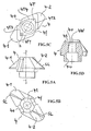
- FIG. 1 around a pivot pin axis B recognizable pivotable locking element 4.
- the Pintle head (not visible in FIG. 1, but probably in FIG. 3A) is accessible at the bottom of the holder 2-1 and can be accessed from be operated from there.
- the locking element 4 - preferably made of metal, in particular aluminum or stainless steel - has the shape of a double leaf 4-1, 4-2 propeller-like structure that bridges the slot S on the inside of the holder edges 1-1 and 1-2 in the locked position with the wing ends.
- the locking element reaches this locking position automatically due to the action of a torsion spring 6 arranged on the pivot pin 3 (see FIG. 4).
- the locking element 4 By rotating the bolt (3) against the force of the torsion spring (6), the locking element 4 can be pivoted into a non-locking position , in which its wing ends do not bridge the slot S, but are aligned along it in such a way that the plug-in part 2-2 together with the locking part 4 can be released from the holding groove.
- a two-armed ejection leaf spring 5 supports the saddle-like over the narrow side of the Locking element 4 is arranged.
- Your free Leaf spring arms 5-1 and 5-2 run obliquely downwards; your Ends protrude slightly from the locking element 4 such that they are in the non-locking position against the outer edges Press 1-1e and 1-1e 'of slot S (see FIG. 2) and that Press the plug-in part at least partially out of the retaining groove.
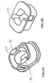
- the holder 2-1 of the insert connection arrangement 2 comprises a base body 2-4 (FIG. 7, FIG. 8A, 8B and 8C) Component connector (2-3) (which with a component is connectable, e.g. by screwing) and a damping part 2-5 (FIG. 3C, FIG. 9A and FIG. 9B).
- FIG.3 show A to C. Perspective representations of the insert connection arrangement 2 according to the invention shown in FIG. 1 in different views.
- FIG. 3A shows a view looking obliquely from below.
- the plug-in part 2-2 has two guide elements 2-4-1 and 2-4-2, between which the locking element 4 is arranged on the pivot pin 3 with the pivot pin axis B.
- These two guide elements permit a secure alignment of the insert connection arrangement 2 with the center of the slot when the plug part is inserted into the slot S of the holding groove 1. Due to the action of the torsion spring arranged on the pivot pin 3 (not visible), the locking element 4 assumes a position which corresponds to the locking position, even when the insert-connection arrangement 2 is not connected to the holding groove 1.
- the torsion spring 6 (FIG. 4) is arranged on the pivot axis; one of its ends is in a bore h (see FIG. 4, FIG. 5C) of the locking element 4; its other end is supported in a recess of the holder or is connected directly to it.
- the Retaining groove ensures that the locking element in a position corresponding to the non-locking position is brought, otherwise the locking element could not be passed through the slot.
- the locking element has a special one geometric shape on FIG. 3B, 4, 5A, 5B and 5C).
- Each of his Wing 4-1, 4-2 has a sliding slope (SL), which at Insert the plug-in part 2-2 into the holding groove 1 in such a way that Slot outer edges 1-1e and 1-1e 'is pressed that the Locking element 4 against the spring (6) in a force the slot S is pivoted position is pivoted.
- the wing arms 4-1 and 4-2 of the locking element 4 are driven by the force of the torsion spring over the inside of the holder edges 1 -1, 2-2 (FIG. 1) in the locking position and thereby effect the connection between the holding groove 1 and the insert connection arrangement 2.
- FIG. 3A are the plug-in part (as in FIG. 1) with 2-2, the holder with 2-1, the base body with 2-4, the component connector with 2-3, the damping part with 2-5 and the ejection leaf spring with 5 designated.
- FIG. 3B shows a view of the insert connection arrangement with a view obliquely from above.
- the names of the individual parts are the same as in FIG. 3A.
- the representation in FIG. 3B is suitable for recognizing the course of the glacial slopes SL.
- the sliding slopes SL are indicated by dots in FIG. 3B; however, this representation of the sliding bevels is only of an auxiliary nature - in practice, the sliding bevel is designed as a slightly curved sliding bevel surface in order to correspond to the pivoting of the locking element as optimally as possible when its wings 4-1 and 4-2 onto the slot outer edges 1-1e and 1- 1e 'when pushing the plug-in part into the holding groove.
- FIG. 3C shows a perspective view of the insert connection arrangement 2 with an approximately lateral viewing direction.
- the names of the individual parts are the same as in FIG. 3A and 3B.
- This illustration also shows how the component connecting piece 2-3 can be designed: for example with two comb-like arms which are to be pinned to the component to be fastened thereon.
- FIG. 4 shows a partial perspective view of the pivotable on the pivot pin 3 locking element 4.
- the locking element 4 is acted upon by a torsion coil spring 6 so that it pivots in the locking position.
- the locking element has stop surfaces 4S1 and 4S2 (4S2 on the back layer), which at a Pivoting of the locking element -in the event that the Insert connection arrangement is connected to the holding groove the inside pages 1-1s of the (not shown in FIG. 4) Hit the retaining edges 1-1 and 1-2 (see FIG. 2) and thereby the Limit swivel movement.
- a click sound is generated, which also makes a acoustic locking control is given.
- the locking element 4 also comprises a diamond-shaped extension 4T with the side surfaces 4T1, 4T2 on the visible front side and with the side surfaces 4T3 and 4T4 on the rear side (see FIG. 5C).
- the pivoting movement of the locking element caused by the torsion coil spring is limited - in the event that the insert-connection arrangement is not connected to the holding groove - by the side surfaces 4T1, 4T2, 4T3 and 4T4 on the wall y of a corresponding recess (FIG. 8C ) of the main body 2-4.
- FIG. 4 shows that the free end of the spring arm 5-1 Ejection leaf spring 5 of the locking element 4 somewhat projects. The same goes for the one on the back of the Locking element extending spring arm 5-2 (not visible).
- FIG. 10 shows a perspective view of this ejection leaf spring 5 with a base part 5B and angled obliquely outwardly extending leaf spring arms 5-1 and 5-2.
- the base part has a bore 5h for the passage of the pivot pin.
- the ejection leaf spring 5 is arranged with its base part in a form-fitting manner in a corresponding recess in the locking part, so that it follows the pivoting movements of the locking part.
- the torsion coil spring 6 seated on the pivot pin 3 is at its upper end in a bore h of the locking element. Its other end (not shown) is supported on the wall of a recess in the base body.
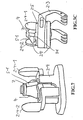
- the pivot pin includes a bolt head 3H, an adjoining smooth shaft part 3F and one Threaded shaft part 3 W of smaller diameter.
- the shaft On the bolt head the shaft has a recess 3R, in which the assembled state a projection v of the body 2-4 (FIG. 8B) engages.
- This bolt lock is through the elastic property of the base material possible. At the Pushing the bolt into the base body widens it Temporarily bore a little bit until the protrusion v in the Puncture area 3R engages.
- the locking part 4 (see FIG. 5D) has one in the upper part Hole 4o with internal thread 4W, which with the threaded shaft part 3 W (FIG. 6) of the pivot pin can be screwed. in the lower part, the locking part 4 has a bore 4u Inclusion of the upper part of the smooth pivot pin shaft part 3F (FIG.6).
- the insert connection arrangement 2 can be inserted into the retaining groove 1 or detached therefrom.
- the locking element 4 is pivoted back against the force of the torsion spring by pressing the outer slot edges 1-1e and 1-1e 'on the sliding slopes SL of the wings 4-1 and 4-2 in a position that a passage of the locking element through the slot S. permitted in the holding groove 1.
- the locking element swivels (torsion) due to the spring force into the locking position. In this position, it can no longer fall out of the holding groove or be pulled out, although it can still be shifted lengthwise in the holding groove.
- the pivot pin (with its external thread) 3W (FIG. 6) is screwed into the internal thread 4W (FIG. 5D) of the locking part 4.
- the wings 4-1 and 4-2 of the locking part 4 are increasingly pulled against the inner sides of the holding edges 1-1 and 1-2, the holding edges being clamped increasingly between the holding part 2-1 and the wings of the locking element.
- this screw connection must first be loosened until the locking piece can be pivoted into the non-locking position by rotating the pivot pin against the force of the torsion spring. Completely unscrewing the pivot pin from the locking piece is not possible since the ring nut 7 seated on the pivot pin above the ejection spring 5 is connected in a torsion-proof manner on its upper side to the pivot pin.
- FIG. 7 shows one schematic perspective view of the main body 2-4 (without component connector, without damping part) with inserted pivot pin with locking element. inserted pivot pin with locking element.
- FIG. 8A to 8C show different views of the base body 2-4 comprising the holder 2-1 and the plug-in part 2-2.
- FIG.8A shows a front view of the base body
- FIG.8B shows a plan view of the base body
- FIG.8C shows a sectional view of the base body according to section BB in FIG.8.
- the base body 2-4 is in one piece and made of plastic, preferably of polyamide. It serves to receive and guide the pivot pin 3 with the torsion spring 6.
- the locking element 4 is arranged on the upper end of the pivot pin.
- a two-part design of the base body is also possible and advantageous for cost and manufacturing reasons. The two parts are connected, for example, by plug-in or welded connections.
- the torsion spring (not visible) is in the recess a of the Base body 2-4 arranged (FIG. 8C). One of their ends is as already mentioned, connected to the locking element, while its other end is against the wall of this recess supported.
- the recess a also takes that diamond-shaped approach 4T of the locking element 4, in of the diamond-shaped part 4T can be pivoted to a limited extent can.
- the stop surfaces 4T1, 4T2, 4T3 and 4T4 of the diamond-shaped Beat part 4T to limit the pivoting movement of the Locking part on appropriately trained wall parts y the recess a. This limitation of the pivotal movement of the Locking element takes effect when the insert locking arrangement is not connected to the holding groove.
- the two guide elements of the base body are also as in other FIG. designated 2-4-1 and 2-4-2.
- the main body 2-4 also serves to accommodate the component connector 2-3 shown in FIG. 3C and the damping part 2-5 shown individually in FIG. 9.
- the component connector is preferably made of plastic, in particular PEI (polyetherimide).
Landscapes
- Engineering & Computer Science (AREA)
- General Engineering & Computer Science (AREA)
- Mechanical Engineering (AREA)
- Snaps, Bayonet Connections, Set Pins, And Snap Rings (AREA)
- Component Parts Of Construction Machinery (AREA)
Applications Claiming Priority (2)
| Application Number | Priority Date | Filing Date | Title |
|---|---|---|---|
| DE20202681U | 2002-02-21 | ||
| DE20202681U DE20202681U1 (de) | 2002-02-21 | 2002-02-21 | Lösbare Einsatz-Verbindungsanordnung für eine Halte-Nut |
Publications (3)
| Publication Number | Publication Date |
|---|---|
| EP1338805A2 true EP1338805A2 (fr) | 2003-08-27 |
| EP1338805A3 EP1338805A3 (fr) | 2004-01-21 |
| EP1338805B1 EP1338805B1 (fr) | 2004-12-29 |
Family
ID=7968065
Family Applications (1)
| Application Number | Title | Priority Date | Filing Date |
|---|---|---|---|
| EP03003630A Expired - Lifetime EP1338805B1 (fr) | 2002-02-21 | 2003-02-18 | Insert de fixation amovible pour gorge de retenue |
Country Status (4)
| Country | Link |
|---|---|
| US (1) | US6837661B2 (fr) |
| EP (1) | EP1338805B1 (fr) |
| CA (1) | CA2419339A1 (fr) |
| DE (2) | DE20202681U1 (fr) |
Cited By (1)
| Publication number | Priority date | Publication date | Assignee | Title |
|---|---|---|---|---|
| CN107965893A (zh) * | 2017-11-30 | 2018-04-27 | Tcl空调器(中山)有限公司 | 一种空调中框安装结构及应用其的空调器 |
Families Citing this family (35)
| Publication number | Priority date | Publication date | Assignee | Title |
|---|---|---|---|---|
| US7674785B2 (en) * | 2000-06-22 | 2010-03-09 | The Procter & Gamble Company | Topical anti-microbial compositions |
| US7410140B2 (en) * | 2003-08-15 | 2008-08-12 | Illinois Tool Works Inc. | Industrial hanger |
| US7401995B2 (en) * | 2005-03-31 | 2008-07-22 | Nissan Technical Center North America, Inc. | Channel connector |
| DE202005020309U1 (de) * | 2005-12-27 | 2007-05-10 | S-Fasteners Gmbh | Verbindungsanordnung für übereinanderliegende Materialschichten |
| DE202005020308U1 (de) * | 2005-12-27 | 2007-05-03 | S-Fasteners Gmbh | Dekompressionsverschluß |
| DE202006004081U1 (de) * | 2006-03-13 | 2007-08-02 | S-Fasterners Gmbh | Anordnung zur lösbaren Befestigung von Bauteilen an einer Decke oder Wand |
| US7766594B2 (en) * | 2006-06-15 | 2010-08-03 | Unistrut International Corporation | Slot nut for securement of channel |
| TW200823029A (en) * | 2006-11-29 | 2008-06-01 | Durq Machinery Corp | Quick release structure and guard assembly of table saw using same |
| DE202006019165U1 (de) * | 2006-12-20 | 2008-05-08 | S-Fasteners Gmbh | Anordnung mit einem Verriegelungs-Element für einen Verriegelungshaken |
| DE202007000112U1 (de) * | 2007-01-02 | 2008-05-15 | S-Fasteners Gmbh | Verriegelungsanordnung mit einem schwenkbaren Verriegelungshaken und einer verschiebbaren Haltestange |
| US7819371B2 (en) * | 2007-07-02 | 2010-10-26 | Illinois Tool Works Inc. | Universal suspended anchor system |
| US20090016843A1 (en) * | 2007-07-13 | 2009-01-15 | Igor Komsitsky | Spacer Assemblies, Apparatus and Methods of Supporting Hardware |
| TW200920232A (en) * | 2007-10-16 | 2009-05-01 | Inventec Corp | Locking device |
| DE102008022253A1 (de) * | 2008-05-06 | 2009-11-12 | Miva Technologies Gmbh | Hochauflösendes Fotoplottverfahren und Anordnung zur hochauflösenden Aufzeichnung eines computergespeicherten Rasterbildes auf einen ebenen lichtempfindlichen Aufzeichnungsträger |
| US8070378B2 (en) * | 2008-12-19 | 2011-12-06 | Nicholas A. Gargaro, III | Channeled track connector |
| DE102009000786A1 (de) * | 2009-02-11 | 2010-08-19 | Hilti Aktiengesellschaft | Befestigungsvorrichtung zur Anordnung an einer Montageschiene |
| US11953146B1 (en) | 2012-07-30 | 2024-04-09 | Yakattack Llc | Accessory mount extension arm |
| US9828073B1 (en) | 2012-07-30 | 2017-11-28 | Luther Cifers, III | Accessory mounting track |
| US9671060B1 (en) | 2012-07-30 | 2017-06-06 | Luther CIFERS | Accessory mounting track |
| DE202012007790U1 (de) * | 2012-08-15 | 2012-11-15 | Wolfgang Rixen | Befestigungssystem |
| USD911829S1 (en) | 2013-07-30 | 2021-03-02 | Luther Cifers, III | Accessory mounting track |
| US10300833B2 (en) | 2014-01-29 | 2019-05-28 | Dowco, Inc. | Resilient cover clip |
| USD773691S1 (en) | 2014-09-29 | 2016-12-06 | Dowco, Inc. | Keder |
| USD773695S1 (en) | 2014-09-29 | 2016-12-06 | Dowco, Inc. | Rail |
| US9623787B2 (en) * | 2015-03-30 | 2017-04-18 | Nissan North America, Inc. | Vehicle tie-down assembly |
| US9975466B2 (en) * | 2015-09-24 | 2018-05-22 | Dura Operating, Llc | Tie down cleat |
| DE102016217657B4 (de) * | 2016-09-15 | 2020-11-12 | Magna Steyr Fahrzeugtechnik Ag & Co Kg | Hammerschraube |
| CN206191809U (zh) * | 2016-09-22 | 2017-05-24 | 广东松下环境系统有限公司 | 换气装置 |
| DE102017104979A1 (de) * | 2017-03-09 | 2018-09-13 | Preh Gmbh | Bedienteillagerung mit verbesserter Blattfederelementbefestigung |
| CN108180194B (zh) * | 2018-03-01 | 2024-02-09 | 上海易扣精密件制造有限公司 | 一种无螺钉化组装的连接锁扣及其应用 |
| TWM582083U (zh) * | 2019-05-24 | 2019-08-11 | 伍鐌科技股份有限公司 | Structure that reduces the height of the fastener |
| US10858071B1 (en) | 2019-10-09 | 2020-12-08 | Dowco, Inc. | Universal cover |
| US11982305B1 (en) * | 2019-11-23 | 2024-05-14 | Yakattack Llc | Accessory mounting track with T-bolt alignment |
| US12049916B2 (en) | 2021-02-05 | 2024-07-30 | Erico International Corporation | Spring nut |
| CN219937522U (zh) * | 2023-06-25 | 2023-10-31 | 泰科电子(苏州)有限公司 | 连接器部件和连接器 |
Citations (1)
| Publication number | Priority date | Publication date | Assignee | Title |
|---|---|---|---|---|
| DE19900267A1 (de) | 1999-01-07 | 2000-07-13 | Hella Kg Hueck & Co | Vorrichtung zum Befestigen eines ersten Teils an einem feststehenden zweiten Teil |
Family Cites Families (11)
| Publication number | Priority date | Publication date | Assignee | Title |
|---|---|---|---|---|
| JP2664700B2 (ja) * | 1988-02-04 | 1997-10-15 | 大洋製器工業株式会社 | コンテナの連結具 |
| DE4128157C1 (fr) * | 1991-08-24 | 1992-09-10 | Walter Stauffenberg Gmbh & Co. Kg, 5980 Werdohl, De | |
| DE4243185A1 (de) | 1992-12-19 | 1994-06-23 | Hilti Ag | Befestigungsvorrichtung |
| US5370488A (en) * | 1993-11-12 | 1994-12-06 | Sykes; Christopher C. | Connector |
| AUPM754294A0 (en) * | 1994-08-18 | 1994-09-08 | Nyholm, Ture | Automatic twistlock |
| NL9401397A (nl) * | 1994-08-30 | 1996-04-01 | Walraven J Van Bv | Inrichting voor het bevestigen van een voorwerp, meer in het bijzonder een leiding, aan een wand. |
| US5593265A (en) * | 1995-08-16 | 1997-01-14 | Chrysler Corporation | Quick-connect stored energy torsional fastener |
| DE19617750C1 (de) | 1996-05-03 | 1997-10-02 | Diag Design Ag | Verankerungseinheit |
| DE29820923U1 (de) * | 1997-12-01 | 1999-02-25 | Halpaus, Wolfgang, 68519 Viernheim | Befestigungselement |
| DK1026415T3 (da) * | 1999-02-03 | 2006-08-21 | Mefa Befestigungs Und Montages | Befæstigelsesindretning |
| SE512275C2 (sv) * | 1999-03-26 | 2000-02-21 | Siemens Elema Ab | Fäste och mottagardel för låsning av ett fäste |
-
2002
- 2002-02-21 DE DE20202681U patent/DE20202681U1/de not_active Expired - Lifetime
-
2003
- 2003-02-18 EP EP03003630A patent/EP1338805B1/fr not_active Expired - Lifetime
- 2003-02-18 DE DE50300215T patent/DE50300215D1/de not_active Expired - Lifetime
- 2003-02-20 US US10/368,637 patent/US6837661B2/en not_active Expired - Lifetime
- 2003-02-20 CA CA002419339A patent/CA2419339A1/fr not_active Abandoned
Patent Citations (1)
| Publication number | Priority date | Publication date | Assignee | Title |
|---|---|---|---|---|
| DE19900267A1 (de) | 1999-01-07 | 2000-07-13 | Hella Kg Hueck & Co | Vorrichtung zum Befestigen eines ersten Teils an einem feststehenden zweiten Teil |
Cited By (2)
| Publication number | Priority date | Publication date | Assignee | Title |
|---|---|---|---|---|
| CN107965893A (zh) * | 2017-11-30 | 2018-04-27 | Tcl空调器(中山)有限公司 | 一种空调中框安装结构及应用其的空调器 |
| CN107965893B (zh) * | 2017-11-30 | 2020-09-22 | Tcl空调器(中山)有限公司 | 一种空调中框安装结构及应用其的空调器 |
Also Published As
| Publication number | Publication date |
|---|---|
| CA2419339A1 (fr) | 2003-08-21 |
| EP1338805B1 (fr) | 2004-12-29 |
| US6837661B2 (en) | 2005-01-04 |
| US20030156919A1 (en) | 2003-08-21 |
| EP1338805A3 (fr) | 2004-01-21 |
| DE20202681U1 (de) | 2002-05-08 |
| DE50300215D1 (de) | 2005-02-03 |
Similar Documents
| Publication | Publication Date | Title |
|---|---|---|
| EP1338805B1 (fr) | Insert de fixation amovible pour gorge de retenue | |
| EP0792628B1 (fr) | Endoprothèse pour une articulation artificielle de la hanche | |
| DE4219681C2 (de) | Einstellbares Abhebescharnier | |
| EP0124838B1 (fr) | Articulation | |
| DE2819744C2 (de) | Scharnier, insbesondere Brillenscharnier | |
| DE60011580T2 (de) | Befestigungsvorrichtung | |
| DE60014228T2 (de) | Verbindungselement für Möbelgestelle | |
| DE112012000934B4 (de) | Schraubenschlüssel-Werkzeug | |
| DE60120503T2 (de) | Befestigungsvorrichtung mit spielausgleich | |
| DE69218010T2 (de) | Klemmenbefestigung | |
| DE102008061854B4 (de) | Scharnier | |
| DE19960432A1 (de) | Scharnier, insbesondere für eine Fahrzeugtür | |
| DE7620591U1 (de) | Drehgriff fuer fenster, tueren o.dgl. | |
| EP1624144A2 (fr) | Charnière réglable montée par vissage | |
| EP1160406A2 (fr) | Charnière avec surface d'appui encochée | |
| DE4420037B4 (de) | Verbindungselement insbesondere zur Montage von Türdrückern, Griffen od. dgl. an Türen, Fenstern od. dgl. | |
| EP2446776B1 (fr) | Dispositif de raccordement pour le raccordement d'un premier et d'un deuxième élément de meuble avec un troisième élément de meuble, jeu de pièces et table | |
| DE2257966A1 (de) | Vorrichtung zum einspannen von schneidplatten | |
| DE20302306U1 (de) | Verbindungselement für den Möbelbau und Verbindungsanordnung | |
| EP0059885A1 (fr) | Paumelle pour la fixation oscillante et/ou basculante d'une porte ou d'une fenêtre à son cadre | |
| AT503129B1 (de) | Verbindungsbeschlag für holzteile | |
| DE29707057U1 (de) | Möbelscharnier | |
| DE10050143A1 (de) | Bolzensicherung | |
| EP1081392A2 (fr) | Ferrure d'assemblage pour le verrouillage de deux éléments | |
| DE3117118A1 (de) | Scharnier, insbesondere fuer tueren, wie tueren von sicherungs- oder schaltkaesten |
Legal Events
| Date | Code | Title | Description |
|---|---|---|---|
| PUAI | Public reference made under article 153(3) epc to a published international application that has entered the european phase |
Free format text: ORIGINAL CODE: 0009012 |
|
| AK | Designated contracting states |
Designated state(s): AT BE BG CH CY CZ DE DK EE ES FI FR GB GR HU IE IT LI LU MC NL PT SE SI SK TR |
|
| AX | Request for extension of the european patent |
Extension state: AL LT LV MK RO |
|
| PUAL | Search report despatched |
Free format text: ORIGINAL CODE: 0009013 |
|
| AK | Designated contracting states |
Kind code of ref document: A3 Designated state(s): AT BE BG CH CY CZ DE DK EE ES FI FR GB GR HU IE IT LI LU MC NL PT SE SI SK TR |
|
| AX | Request for extension of the european patent |
Extension state: AL LT LV MK RO |
|
| RIC1 | Information provided on ipc code assigned before grant |
Ipc: 7F 16B 21/02 A Ipc: 7F 16B 17/00 B Ipc: 7F 16B 37/04 B |
|
| 17P | Request for examination filed |
Effective date: 20040211 |
|
| GRAP | Despatch of communication of intention to grant a patent |
Free format text: ORIGINAL CODE: EPIDOSNIGR1 |
|
| GRAS | Grant fee paid |
Free format text: ORIGINAL CODE: EPIDOSNIGR3 |
|
| AKX | Designation fees paid |
Designated state(s): DE ES FR GB |
|
| GRAA | (expected) grant |
Free format text: ORIGINAL CODE: 0009210 |
|
| AK | Designated contracting states |
Kind code of ref document: B1 Designated state(s): DE ES FR GB |
|
| REG | Reference to a national code |
Ref country code: GB Ref legal event code: FG4D Free format text: NOT ENGLISH |
|
| REG | Reference to a national code |
Ref country code: IE Ref legal event code: FG4D Free format text: GERMAN |
|
| REF | Corresponds to: |
Ref document number: 50300215 Country of ref document: DE Date of ref document: 20050203 Kind code of ref document: P |
|
| GBT | Gb: translation of ep patent filed (gb section 77(6)(a)/1977) |
Effective date: 20050420 |
|
| PLBE | No opposition filed within time limit |
Free format text: ORIGINAL CODE: 0009261 |
|
| STAA | Information on the status of an ep patent application or granted ep patent |
Free format text: STATUS: NO OPPOSITION FILED WITHIN TIME LIMIT |
|
| 26N | No opposition filed |
Effective date: 20050930 |
|
| ET | Fr: translation filed | ||
| REG | Reference to a national code |
Ref country code: GB Ref legal event code: 732E |
|
| REG | Reference to a national code |
Ref country code: FR Ref legal event code: TP |
|
| PGFP | Annual fee paid to national office [announced via postgrant information from national office to epo] |
Ref country code: ES Payment date: 20070228 Year of fee payment: 5 |
|
| PG25 | Lapsed in a contracting state [announced via postgrant information from national office to epo] |
Ref country code: ES Free format text: THE PATENT HAS BEEN ANNULLED BY A DECISION OF A NATIONAL AUTHORITY Effective date: 20050409 |
|
| REG | Reference to a national code |
Ref country code: DE Ref legal event code: R082 Ref document number: 50300215 Country of ref document: DE Representative=s name: SCHUMACHER & WILLSAU PATENTANWALTSGESELLSCHAFT, DE |
|
| PGFP | Annual fee paid to national office [announced via postgrant information from national office to epo] |
Ref country code: GB Payment date: 20130225 Year of fee payment: 11 |
|
| GBPC | Gb: european patent ceased through non-payment of renewal fee |
Effective date: 20140218 |
|
| PG25 | Lapsed in a contracting state [announced via postgrant information from national office to epo] |
Ref country code: GB Free format text: LAPSE BECAUSE OF NON-PAYMENT OF DUE FEES Effective date: 20140218 |
|
| REG | Reference to a national code |
Ref country code: FR Ref legal event code: PLFP Year of fee payment: 14 |
|
| REG | Reference to a national code |
Ref country code: FR Ref legal event code: PLFP Year of fee payment: 15 |
|
| REG | Reference to a national code |
Ref country code: FR Ref legal event code: PLFP Year of fee payment: 16 |
|
| PGFP | Annual fee paid to national office [announced via postgrant information from national office to epo] |
Ref country code: DE Payment date: 20180212 Year of fee payment: 16 |
|
| PGFP | Annual fee paid to national office [announced via postgrant information from national office to epo] |
Ref country code: FR Payment date: 20180223 Year of fee payment: 16 |
|
| REG | Reference to a national code |
Ref country code: DE Ref legal event code: R119 Ref document number: 50300215 Country of ref document: DE |
|
| PG25 | Lapsed in a contracting state [announced via postgrant information from national office to epo] |
Ref country code: DE Free format text: LAPSE BECAUSE OF NON-PAYMENT OF DUE FEES Effective date: 20190903 |
|
| PG25 | Lapsed in a contracting state [announced via postgrant information from national office to epo] |
Ref country code: FR Free format text: LAPSE BECAUSE OF NON-PAYMENT OF DUE FEES Effective date: 20190228 |