EP1624144A2 - Charnière réglable montée par vissage - Google Patents
Charnière réglable montée par vissage Download PDFInfo
- Publication number
- EP1624144A2 EP1624144A2 EP05014588A EP05014588A EP1624144A2 EP 1624144 A2 EP1624144 A2 EP 1624144A2 EP 05014588 A EP05014588 A EP 05014588A EP 05014588 A EP05014588 A EP 05014588A EP 1624144 A2 EP1624144 A2 EP 1624144A2
- Authority
- EP
- European Patent Office
- Prior art keywords
- hinge
- adapter
- longitudinal slot
- components
- screw
- Prior art date
- Legal status (The legal status is an assumption and is not a legal conclusion. Google has not performed a legal analysis and makes no representation as to the accuracy of the status listed.)
- Withdrawn
Links
- 238000006073 displacement reaction Methods 0.000 claims abstract description 9
- 238000003780 insertion Methods 0.000 claims description 2
- 230000037431 insertion Effects 0.000 claims description 2
- 230000000149 penetrating effect Effects 0.000 claims description 2
- 230000001771 impaired effect Effects 0.000 description 1
- 238000004519 manufacturing process Methods 0.000 description 1
- 239000002184 metal Substances 0.000 description 1
- 238000012986 modification Methods 0.000 description 1
- 230000004048 modification Effects 0.000 description 1
Images
Classifications
-
- E—FIXED CONSTRUCTIONS
- E05—LOCKS; KEYS; WINDOW OR DOOR FITTINGS; SAFES
- E05D—HINGES OR SUSPENSION DEVICES FOR DOORS, WINDOWS OR WINGS
- E05D5/00—Construction of single parts, e.g. the parts for attachment
- E05D5/02—Parts for attachment, e.g. flaps
- E05D5/0215—Parts for attachment, e.g. flaps for attachment to profile members or the like
- E05D5/0223—Parts for attachment, e.g. flaps for attachment to profile members or the like with parts, e.g. screws, extending through the profile wall or engaging profile grooves
- E05D5/023—Parts for attachment, e.g. flaps for attachment to profile members or the like with parts, e.g. screws, extending through the profile wall or engaging profile grooves with parts extending through the profile wall
-
- E—FIXED CONSTRUCTIONS
- E05—LOCKS; KEYS; WINDOW OR DOOR FITTINGS; SAFES
- E05D—HINGES OR SUSPENSION DEVICES FOR DOORS, WINDOWS OR WINGS
- E05D7/00—Hinges or pivots of special construction
- E05D7/04—Hinges adjustable relative to the wing or the frame
-
- E—FIXED CONSTRUCTIONS
- E05—LOCKS; KEYS; WINDOW OR DOOR FITTINGS; SAFES
- E05D—HINGES OR SUSPENSION DEVICES FOR DOORS, WINDOWS OR WINGS
- E05D7/00—Hinges or pivots of special construction
- E05D7/04—Hinges adjustable relative to the wing or the frame
- E05D7/0415—Hinges adjustable relative to the wing or the frame with adjusting drive means
-
- E—FIXED CONSTRUCTIONS
- E05—LOCKS; KEYS; WINDOW OR DOOR FITTINGS; SAFES
- E05D—HINGES OR SUSPENSION DEVICES FOR DOORS, WINDOWS OR WINGS
- E05D5/00—Construction of single parts, e.g. the parts for attachment
- E05D5/02—Parts for attachment, e.g. flaps
- E05D5/04—Flat flaps
-
- E—FIXED CONSTRUCTIONS
- E05—LOCKS; KEYS; WINDOW OR DOOR FITTINGS; SAFES
- E05Y—INDEXING SCHEME ASSOCIATED WITH SUBCLASSES E05D AND E05F, RELATING TO CONSTRUCTION ELEMENTS, ELECTRIC CONTROL, POWER SUPPLY, POWER SIGNAL OR TRANSMISSION, USER INTERFACES, MOUNTING OR COUPLING, DETAILS, ACCESSORIES, AUXILIARY OPERATIONS NOT OTHERWISE PROVIDED FOR, APPLICATION THEREOF
- E05Y2900/00—Application of doors, windows, wings or fittings thereof
- E05Y2900/20—Application of doors, windows, wings or fittings thereof for furniture, e.g. cabinets
Definitions
- the invention relates to a Anschraubscharnier consisting of a first and a second hinge wing, each having a plurality of openings for receiving the means of the hinge to each other to be supported components in associated holes penetrating mounting screws, wherein the two hinge wings are connected to each other via a hinge axis.
- a screw-on hinge with the aforementioned features is described in DE 295 14 712 U1.
- a screw-on hinge should be used especially in existing from thin-walled sheet metal cabinets used, there is generally the problem that can be forgiven by means of the hinge to each other to be held components such as cabinet body and associated door or flap, so that difficulties occur during assembly of the hinge can.
- the openings in the hinge wings for receiving the fastening screws are formed as slots, wherein the orientation of the slots in the one hinge wing is substantially perpendicular to the alignment in the other hinge wing. In this way, a two-dimensional alignment possibility for the hinge is already opened.
- the known hinge has the disadvantage that the hinge is displaceable only in the axes of the slots; In addition, the appearance of the hinge is impaired on its outer side by the recognizable slots there.
- the invention is therefore based on the object in a hinge with the generic features to improve the alignability of the hinge and on the visible side of the hinge this alignability optically not be seen.
- the invention provides in its basic idea that arranged on the back of the components each one with a projection in the holes of the components centering adapter for receiving a cooperating with the fastening screw nut and in the adapter a diametrically extending longitudinal slot for positive, non-rotatable recording the slidable in the longitudinal slot nut is formed and that the diameter of the holes located in the components by the amount of displacement of the hinge is greater than the diameter of the mounting screws.
- the invention is based on the principle the alignment of the hinge wings is effected in each case by rotation of the associated adapter with an alignment of its longitudinal slot in the direction of the desired displacement of the hinge wing; Since the adapter centered by means of its centering projection in a larger diameter than the diameter of the fastening screw having bore of the corresponding component, a rotation of the adapter causes the fixed by the pre-mounted fastening screw nut moves forcibly guided in the slot of the adapter and the Fixing screw in the context of the defined by the size of the bore in the component motion play entrains.
- a displacement of the fastening screw and thus of this in the recessed apertures form-fitting content Erten hinge wing in any direction without restriction.
- the longitudinal slot formed in the body of the adapter is bounded on both sides by the screw nut at its edge regions and leading to their displacement in the longitudinal slot grooves. This ensures that the forcefully guided in the context of the alignment of a hinge wing displacement of the nut takes place in the longitudinal slot of the adapter without problems.
- the longitudinal slot is formed open on one side for insertion of the nut.
- the nut is incorporated in the manufacture of the adapter in the longitudinal slot with.
- the body of the adapter projecting away from the component has at its free end a polygonal shape for fitting a suitable tool, so that good handling is ensured in the rotation of the adapter required for the adjustment of the hinge.
- the centering projection of the adapter is designed in the form of two half shells aligned opposite one another and aligned in the course of the longitudinal slot; As a result, the friction of the adapter relative to the edge regions of the half-shells receiving bore in the associated component is reduced, wherein the half-shells increase the stability of the centering of the adapter in the bore of the component in the direction of displacement of the nut.
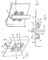
- a hinge 12 serves to hold a door 11 on a cabinet body 10.
- the hinge 12 consists of a first hinge wing 13 fastened to the cabinet body 10 and a second hinge wing 14 fastened to the door 11. wherein the two hinge wings are coupled or connected to each other by means of a hinge axis 15.
- the attachment of the hinge wing 13, 14 via inserted in corresponding recessed apertures 16 fastening screws 17 with countersunk, the fastening screws 17 pass through the cabinet body 10 and the door 11 in non-visible holes.
- the fastening of the hinge 12 takes place in the manner described below.
- an adapter 18 is mounted in each case, and this adapter 18 is centered with a centering projection consisting of two opposite half shells 25 ( Figure 5) in the associated bore in the cabinet body 10 and door 11.
- This bore has a larger diameter than that Diameter of the fastening screw 17, so that the fastening screw 17 with its screw shank 24 in the bore of the cabinet body 10 and door 11 is displaced.
- the extent of the diameter increase of the bore depends on the desired degree of displaceability of the hinge 12 on the surface of the cabinet body 10 and door 11.
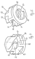
- the adapter 18 forms in its body 19 a diametrical longitudinal slot 20 which is bounded on both sides of its course by grooves 21.
- a nut 23 is inserted such that the nut 23 is slidable in the grooves 21 and in the longitudinal slot 20, but otherwise with respect to the adapter 18 is non-rotatable.
- the screw shank 24 of the fastening screw 17 can be screwed.
- the region of the body 19 of the adapter 18 protruding from the cabinet body 10 or door 11 is designed in the form of a polygon 22, so that the adapter 18 with its centering projection in the form of the half-shells 25 in the bore of FIG Cabinet 10 and door 11 can be rotated.
- the hinge is first preassembled by screwing in the fastening screws 17 into the screw nuts 23 inserted into the longitudinal slot 20 of the rear-mounted adapter 18, so that the hinge 12 is already prefixed to the cabinet body 10 or door 11. If an alignment of the hinge 12 is required, the adapter 18 can be rotated by means of the tool placed on the polygon 22 of the adapter 18, whereby due to the fixation of the screw nut 23 by the fastening screw 17 in the slot 20 upon rotation of the adapter 18 a forced displacement the screw nut 23 takes place in the longitudinal slot 20.
- the longitudinal slot 20 of the adapter 18 is rotated in the direction in which the orientation of the hinge by a rectified movement of the screw shank 24 in the associated bore of cabinet body 10 and door 11 is to take place. If the desired aligned position and position of the screw shank 24 is reached in the associated bore, the fastening screw 17 is tightened.
Landscapes
- Engineering & Computer Science (AREA)
- Mechanical Engineering (AREA)
- Hinges (AREA)
Applications Claiming Priority (1)
| Application Number | Priority Date | Filing Date | Title |
|---|---|---|---|
| DE202004012344U DE202004012344U1 (de) | 2004-08-05 | 2004-08-05 | Verstellbares Anschraubscharnier |
Publications (2)
| Publication Number | Publication Date |
|---|---|
| EP1624144A2 true EP1624144A2 (fr) | 2006-02-08 |
| EP1624144A3 EP1624144A3 (fr) | 2009-09-16 |
Family
ID=33395442
Family Applications (1)
| Application Number | Title | Priority Date | Filing Date |
|---|---|---|---|
| EP05014588A Withdrawn EP1624144A3 (fr) | 2004-08-05 | 2005-07-06 | Charnière réglable montée par vissage |
Country Status (3)
| Country | Link |
|---|---|
| US (1) | US7360279B2 (fr) |
| EP (1) | EP1624144A3 (fr) |
| DE (1) | DE202004012344U1 (fr) |
Cited By (1)
| Publication number | Priority date | Publication date | Assignee | Title |
|---|---|---|---|---|
| CN104068618A (zh) * | 2014-07-10 | 2014-10-01 | 常州富兰德户外休闲用品有限公司 | 翻转折叠储物桌 |
Families Citing this family (9)
| Publication number | Priority date | Publication date | Assignee | Title |
|---|---|---|---|---|
| JP4758357B2 (ja) * | 2004-01-26 | 2011-08-24 | ラムザウア ディーター | 開口部に取付けるためのヒンジ |
| DE202008005541U1 (de) | 2008-04-21 | 2008-07-10 | Emka Beschlagteile Gmbh & Co. Kg | Beschlagteil mit Schnellmontageeinrichtung |
| CA2749550C (fr) * | 2009-01-22 | 2014-09-30 | Austin R. Baer | Systeme de montage de porte reglable |
| JP6468989B2 (ja) * | 2015-11-23 | 2019-02-13 | 西谷 均 | 嵌め込み機構と建付け調整機構を有する建具装着用嵌合部材。 |
| DE202016003803U1 (de) * | 2016-06-17 | 2017-09-20 | Dieter Ramsauer | Scharniersystem |
| CN107882454A (zh) * | 2017-11-16 | 2018-04-06 | 李新亚 | 高度可调滚珠合页 |
| CN110469222B (zh) * | 2019-09-04 | 2021-01-08 | 浙江永强集团股份有限公司 | 一种家具铰链 |
| US11931882B2 (en) * | 2021-06-02 | 2024-03-19 | Guy Clapp | Tool holding system |
| US20240209883A1 (en) * | 2021-06-02 | 2024-06-27 | Guy Clifford Clapp | Hinge-locking system |
Citations (1)
| Publication number | Priority date | Publication date | Assignee | Title |
|---|---|---|---|---|
| DE29514712U1 (de) | 1995-09-13 | 1997-01-16 | Ramsauer, Dieter, 42555 Velbert | Anschraubscharnier |
Family Cites Families (10)
| Publication number | Priority date | Publication date | Assignee | Title |
|---|---|---|---|---|
| US566323A (en) * | 1896-08-25 | Gate-hinge | ||
| US2477429A (en) * | 1943-05-15 | 1949-07-26 | K A Swanstrom | Holder for fastener elements |
| US3053355A (en) * | 1957-07-22 | 1962-09-11 | Charles W Attwood | Curved nut with edges to bite into channel flanges |
| US4575295A (en) * | 1984-01-11 | 1986-03-11 | Gte Products Corporation | Fastener for channeled structural members |
| DE3805095A1 (de) * | 1988-02-18 | 1989-08-31 | Casma Spa | Tuer oder fenster mit verstellbarem scharnier |
| WO1992011156A1 (fr) * | 1990-12-20 | 1992-07-09 | Audi Ag | Montant de porte d'une carrosserie de voiture automobile |
| DE19646575A1 (de) * | 1996-11-12 | 1998-05-14 | Joachim Fischbach | Vorrichtung zur justierbaren Halterung von Platten, insbesondere von Glasscheiben oder dergleichen |
| US6286185B1 (en) * | 1998-03-17 | 2001-09-11 | Dieter Ramsauer | Hinge for metal cupboard doors |
| US6502282B1 (en) * | 1998-04-23 | 2003-01-07 | Ron E. King | Apparatus for connecting a cabinet door hinge to a frameless cabinet wall |
| SE516342C2 (sv) * | 2000-04-27 | 2001-12-17 | Jokab Safety Ab | Insticksmutter till ett skruv-mutter-förband |
-
2004
- 2004-08-05 DE DE202004012344U patent/DE202004012344U1/de not_active Expired - Lifetime
-
2005
- 2005-07-06 EP EP05014588A patent/EP1624144A3/fr not_active Withdrawn
- 2005-08-05 US US11/203,582 patent/US7360279B2/en not_active Expired - Fee Related
Patent Citations (1)
| Publication number | Priority date | Publication date | Assignee | Title |
|---|---|---|---|---|
| DE29514712U1 (de) | 1995-09-13 | 1997-01-16 | Ramsauer, Dieter, 42555 Velbert | Anschraubscharnier |
Cited By (2)
| Publication number | Priority date | Publication date | Assignee | Title |
|---|---|---|---|---|
| CN104068618A (zh) * | 2014-07-10 | 2014-10-01 | 常州富兰德户外休闲用品有限公司 | 翻转折叠储物桌 |
| CN104068618B (zh) * | 2014-07-10 | 2022-09-02 | 常州富兰德户外休闲用品有限公司 | 翻转折叠储物桌 |
Also Published As
| Publication number | Publication date |
|---|---|
| EP1624144A3 (fr) | 2009-09-16 |
| US7360279B2 (en) | 2008-04-22 |
| DE202004012344U1 (de) | 2004-10-21 |
| US20060026796A1 (en) | 2006-02-09 |
Similar Documents
| Publication | Publication Date | Title |
|---|---|---|
| EP1338805B1 (fr) | Insert de fixation amovible pour gorge de retenue | |
| EP1153186B1 (fr) | Raccord permettant de connecter deux parois minces | |
| DE2514357B2 (de) | Beschlag zum verschwenkbaren Verbinden einer Möbelplatte mit einem feststehenden Möbelteil | |
| EP1653031B1 (fr) | Charnière de porte pliante | |
| DE69733852T2 (de) | Verstellnockeneinrichtung für Möbelbeschlagteile und Beschlagteile mit solch einer Einrichtung | |
| EP1624144A2 (fr) | Charnière réglable montée par vissage | |
| WO2000014371A1 (fr) | Charniere a visser comportant une position d'arret | |
| DE19517924B4 (de) | Möbelbeschlagteil | |
| EP0215281B1 (fr) | Palier pour un battant de fenêtre, porte ou similaire | |
| EP0991836B1 (fr) | Charniere pour portes d'armoire metallique | |
| DE19733471C1 (de) | Langlochführung zwischen zwei Bauteilen | |
| DE4336326C5 (de) | Als Scharniertopf ausgebildeter Tür-Anschlagteil für Möbelscharniere | |
| EP2565351A2 (fr) | Agencement de poignée | |
| EP2208843B1 (fr) | Charnière pour une porte | |
| EP0592854B1 (fr) | Dispositif de montage d'une poignée de porte amovible | |
| EP3363969A1 (fr) | Poignée d'actionnement | |
| DE10119986C1 (de) | Lagerung und Befestigung einer Stange | |
| EP0760890B1 (fr) | Charniere en plusieurs parties | |
| EP1243214A2 (fr) | Charnière et panneau de séparation, en particulier cabine de douche avec charnière pour permettre la rotation d'une porte en verre | |
| DE102014103637B4 (de) | Topflocheinsatz, Blendenbefestigungselement und Topfscharnier | |
| DE3040287A1 (de) | Tuerscharnier mit druckvorrichtung | |
| WO2003069101A2 (fr) | Systeme d'encliquetage et element a encliquetage | |
| DE202008005541U1 (de) | Beschlagteil mit Schnellmontageeinrichtung | |
| DE3117118A1 (de) | Scharnier, insbesondere fuer tueren, wie tueren von sicherungs- oder schaltkaesten | |
| DE8420175U1 (de) | Haushaltsgeraet mit einem blendenkoerper |
Legal Events
| Date | Code | Title | Description |
|---|---|---|---|
| PUAI | Public reference made under article 153(3) epc to a published international application that has entered the european phase |
Free format text: ORIGINAL CODE: 0009012 |
|
| AK | Designated contracting states |
Kind code of ref document: A2 Designated state(s): AT BE BG CH CY CZ DE DK EE ES FI FR GB GR HU IE IS IT LI LT LU LV MC NL PL PT RO SE SI SK TR |
|
| AX | Request for extension of the european patent |
Extension state: AL BA HR MK YU |
|
| PUAL | Search report despatched |
Free format text: ORIGINAL CODE: 0009013 |
|
| AK | Designated contracting states |
Kind code of ref document: A3 Designated state(s): AT BE BG CH CY CZ DE DK EE ES FI FR GB GR HU IE IS IT LI LT LU LV MC NL PL PT RO SE SI SK TR |
|
| AX | Request for extension of the european patent |
Extension state: AL BA HR MK YU |
|
| AKX | Designation fees paid | ||
| STAA | Information on the status of an ep patent application or granted ep patent |
Free format text: STATUS: THE APPLICATION IS DEEMED TO BE WITHDRAWN |
|
| 18D | Application deemed to be withdrawn |
Effective date: 20100317 |
|
| REG | Reference to a national code |
Ref country code: DE Ref legal event code: 8566 |