EP1339096A2 - Ultraschalhorn und Ultraschalbondvorrichtung, die das Ultraschalhorn verwendet - Google Patents
Ultraschalhorn und Ultraschalbondvorrichtung, die das Ultraschalhorn verwendet Download PDFInfo
- Publication number
- EP1339096A2 EP1339096A2 EP03004098A EP03004098A EP1339096A2 EP 1339096 A2 EP1339096 A2 EP 1339096A2 EP 03004098 A EP03004098 A EP 03004098A EP 03004098 A EP03004098 A EP 03004098A EP 1339096 A2 EP1339096 A2 EP 1339096A2
- Authority
- EP
- European Patent Office
- Prior art keywords
- ultrasonic
- horn
- bonded
- vibration
- vibrations
- Prior art date
- Legal status (The legal status is an assumption and is not a legal conclusion. Google has not performed a legal analysis and makes no representation as to the accuracy of the status listed.)
- Withdrawn
Links
Images







Classifications
-
- H—ELECTRICITY
- H05—ELECTRIC TECHNIQUES NOT OTHERWISE PROVIDED FOR
- H05K—PRINTED CIRCUITS; CASINGS OR CONSTRUCTIONAL DETAILS OF ELECTRIC APPARATUS; MANUFACTURE OF ASSEMBLAGES OF ELECTRICAL COMPONENTS
- H05K13/00—Apparatus or processes specially adapted for manufacturing or adjusting assemblages of electric components
- H05K13/04—Mounting of components, e.g. of leadless components
- H05K13/046—Surface mounting
-
- B—PERFORMING OPERATIONS; TRANSPORTING
- B06—GENERATING OR TRANSMITTING MECHANICAL VIBRATIONS IN GENERAL
- B06B—METHODS OR APPARATUS FOR GENERATING OR TRANSMITTING MECHANICAL VIBRATIONS OF INFRASONIC, SONIC, OR ULTRASONIC FREQUENCY, e.g. FOR PERFORMING MECHANICAL WORK IN GENERAL
- B06B3/00—Methods or apparatus specially adapted for transmitting mechanical vibrations of infrasonic, sonic, or ultrasonic frequency
-
- B—PERFORMING OPERATIONS; TRANSPORTING
- B23—MACHINE TOOLS; METAL-WORKING NOT OTHERWISE PROVIDED FOR
- B23K—SOLDERING OR UNSOLDERING; WELDING; CLADDING OR PLATING BY SOLDERING OR WELDING; CUTTING BY APPLYING HEAT LOCALLY, e.g. FLAME CUTTING; WORKING BY LASER BEAM
- B23K20/00—Non-electric welding by applying impact or other pressure, with or without the application of heat, e.g. cladding or plating
- B23K20/10—Non-electric welding by applying impact or other pressure, with or without the application of heat, e.g. cladding or plating making use of vibrations, e.g. ultrasonic welding
- B23K20/106—Features related to sonotrodes
-
- H—ELECTRICITY
- H10—SEMICONDUCTOR DEVICES; ELECTRIC SOLID-STATE DEVICES NOT OTHERWISE PROVIDED FOR
- H10P—GENERIC PROCESSES OR APPARATUS FOR THE MANUFACTURE OR TREATMENT OF DEVICES COVERED BY CLASS H10
- H10P72/00—Handling or holding of wafers, substrates or devices during manufacture or treatment thereof
- H10P72/04—Apparatus for manufacture or treatment
- H10P72/0428—Apparatus for mechanical treatment or grinding or cutting
-
- H—ELECTRICITY
- H10—SEMICONDUCTOR DEVICES; ELECTRIC SOLID-STATE DEVICES NOT OTHERWISE PROVIDED FOR
- H10P—GENERIC PROCESSES OR APPARATUS FOR THE MANUFACTURE OR TREATMENT OF DEVICES COVERED BY CLASS H10
- H10P72/00—Handling or holding of wafers, substrates or devices during manufacture or treatment thereof
- H10P72/04—Apparatus for manufacture or treatment
- H10P72/0438—Apparatus for making assemblies not otherwise provided for, e.g. package constructions
-
- H—ELECTRICITY
- H10—SEMICONDUCTOR DEVICES; ELECTRIC SOLID-STATE DEVICES NOT OTHERWISE PROVIDED FOR
- H10P—GENERIC PROCESSES OR APPARATUS FOR THE MANUFACTURE OR TREATMENT OF DEVICES COVERED BY CLASS H10
- H10P72/00—Handling or holding of wafers, substrates or devices during manufacture or treatment thereof
- H10P72/04—Apparatus for manufacture or treatment
- H10P72/0446—Apparatus for mounting on conductive members, e.g. leadframes or conductors on insulating substrates
-
- H—ELECTRICITY
- H10—SEMICONDUCTOR DEVICES; ELECTRIC SOLID-STATE DEVICES NOT OTHERWISE PROVIDED FOR
- H10W—GENERIC PACKAGES, INTERCONNECTIONS, CONNECTORS OR OTHER CONSTRUCTIONAL DETAILS OF DEVICES COVERED BY CLASS H10
- H10W72/00—Interconnections or connectors in packages
- H10W72/071—Connecting or disconnecting
- H10W72/0711—Apparatus therefor
-
- H—ELECTRICITY
- H10—SEMICONDUCTOR DEVICES; ELECTRIC SOLID-STATE DEVICES NOT OTHERWISE PROVIDED FOR
- H10W—GENERIC PACKAGES, INTERCONNECTIONS, CONNECTORS OR OTHER CONSTRUCTIONAL DETAILS OF DEVICES COVERED BY CLASS H10
- H10W72/00—Interconnections or connectors in packages
- H10W72/071—Connecting or disconnecting
- H10W72/0711—Apparatus therefor
- H10W72/07141—Means for applying energy, e.g. ovens or lasers
-
- H—ELECTRICITY
- H10—SEMICONDUCTOR DEVICES; ELECTRIC SOLID-STATE DEVICES NOT OTHERWISE PROVIDED FOR
- H10W—GENERIC PACKAGES, INTERCONNECTIONS, CONNECTORS OR OTHER CONSTRUCTIONAL DETAILS OF DEVICES COVERED BY CLASS H10
- H10W72/00—Interconnections or connectors in packages
- H10W72/071—Connecting or disconnecting
- H10W72/072—Connecting or disconnecting of bump connectors
- H10W72/07231—Techniques
- H10W72/07232—Compression bonding, e.g. thermocompression bonding
- H10W72/07233—Ultrasonic bonding, e.g. thermosonic bonding
-
- H—ELECTRICITY
- H10—SEMICONDUCTOR DEVICES; ELECTRIC SOLID-STATE DEVICES NOT OTHERWISE PROVIDED FOR
- H10W—GENERIC PACKAGES, INTERCONNECTIONS, CONNECTORS OR OTHER CONSTRUCTIONAL DETAILS OF DEVICES COVERED BY CLASS H10
- H10W72/00—Interconnections or connectors in packages
- H10W72/071—Connecting or disconnecting
- H10W72/072—Connecting or disconnecting of bump connectors
- H10W72/07231—Techniques
- H10W72/07236—Soldering or alloying
-
- H—ELECTRICITY
- H10—SEMICONDUCTOR DEVICES; ELECTRIC SOLID-STATE DEVICES NOT OTHERWISE PROVIDED FOR
- H10W—GENERIC PACKAGES, INTERCONNECTIONS, CONNECTORS OR OTHER CONSTRUCTIONAL DETAILS OF DEVICES COVERED BY CLASS H10
- H10W72/00—Interconnections or connectors in packages
- H10W72/071—Connecting or disconnecting
- H10W72/072—Connecting or disconnecting of bump connectors
- H10W72/07251—Connecting or disconnecting of bump connectors characterised by changes in properties of the bump connectors during connecting
-
- H—ELECTRICITY
- H10—SEMICONDUCTOR DEVICES; ELECTRIC SOLID-STATE DEVICES NOT OTHERWISE PROVIDED FOR
- H10W—GENERIC PACKAGES, INTERCONNECTIONS, CONNECTORS OR OTHER CONSTRUCTIONAL DETAILS OF DEVICES COVERED BY CLASS H10
- H10W72/00—Interconnections or connectors in packages
- H10W72/20—Bump connectors, e.g. solder bumps or copper pillars; Dummy bumps; Thermal bumps
Definitions
- the present invention relates to an ultrasonic horn for applying ultrasonic vibrations to multiple objects to be bonded so as to bond them, and to an ultrasonic bonding apparatus using the ultrasonic horn.
- Patent Reference 1 Japanese Unexamined Patent Application Publication No. 2001-44242
- Patent Reference 2 Japanese Unexamined Patent Application Publication No. 2001-110850.
- Ultrasonic bonding apparatuses are used in the process of flip chip mounting of electronic parts, such as semiconductor devices and piezoelectric devices, on boards.
- Patent Reference 1 discloses an ultrasonic bonding apparatus wherein a member to be bonded to a face is subjected to a pressing load and ultrasonic vibrations, so as to be bonded to the face.
- This ultrasonic bonding apparatus has a vibrator mounted on the tip of a pointed horn, for applying vertical vibrations, which are vibrations in the longitudinal direction of the horn, and a bonding tool positioned at the loop of standing waves of the vertical vibrations of the horn, approximately orthogonal to the direction of vertical vibrations from the horn.
- a connector with pressing means for applying a pressing load is provided at the approximate center of the horn.
- Patent Reference 2 discloses an ultrasonic bonding apparatus wherein a generally T-shaped horn is turned sideways, a vibrator is attached to one end of the sidebar portion thereof, and the vertical bar is formed in a cylindrical shape through which a holding member is passed, and pressing means for applying the pressing load is connected to the tip of this holding member.
- the means for applying the pressing load i.e., the holding member
- the means for applying ultrasonic waves i.e., the horn
- the holding member for applying the pressing load to the bonding portion and the cylindrical portion of the horn for applying the ultrasonic vibrations are not completely separate but rather in contact, so vibrations are also applied to the holding member. Accordingly, the vibrations applied to the bonding portion have multiple modes, so vibrations suitable for bonding cannot be applied. Also, the tip of the T-shaped horn in contact with the bonding portion flexes and vibrates, so ultrasonic vibrations cannot be applied to the bonding face in a constant direction. This causes a problem of poor bonding quality at the bonding portion.
- the present invention addresses these problems by providing an ultrasonic horn capable of applying ultrasonic vibrations in a constant direction to the bonding face, yielding uniform and high-quality bonding.
- the invention also provides an ultrasonic bonding apparatus wherein flexing does not occur at the ultrasonic horn due to the applied load, thereby applying ultrasonic vibrations in a constant direction to the entire bonding face, yielding uniform and high-quality bonding.
- an ultrasonic horn for applying ultrasonic vibrations to bond an object to another object comprises: a main horn unit having left and right apexes and a lower apex, formed generally symmetrical horizontally; a vibration input portion provided at at least one of the left and right apexes of the main horn unit; and a vibration output portion provided at the lower apex of the main horn unit for providing ultrasonic vibrations to the object to be bonded; wherein, when ultrasonic vibrations are input to the vibration input portion in a direction generally toward the vibration output portion, ultrasonic vibrations generally perpendicular to the symmetry axis of the main horn unit are output from the vibration output portion.
- an ultrasonic bonding apparatus for applying a pressing load and ultrasonic vibrations to bond an object to another object, comprises: an ultrasonic horn having left and right apexes and a lower apex, formed generally symmetrical horizontally, the horn comprising a vibration input portion provided at at least one of the left and right apexes, a vibration output portion provided at the lower apex, and a load application portion positioned above the lower apex of the main horn unit and near the symmetry axis thereof; a vibration input device attached to the vibration input portion of the ultrasonic horn, for inputting ultrasonic vibrations to the vibration input portion in a direction generally toward the vibration output portion; and a load applying device linked to the load application portion of the ultrasonic horn, for applying a downward pressing load to the ultrasonic horn; wherein the ultrasonic horn is positioned such that the vibration output portion applies a pressing load and ultrasonic vibrations to the object to
- an ultrasonic bonding method for applying a pressing load and ultrasonic vibrations to bond an object to another object comprises the steps of: providing an ultrasonic horn having left and right apexes and a lower apex, formed generally symmetrical horizontally, the horn comprising a vibration input portion provided at at least one of the left and right apexes, a vibration output portion provided at the lower apex, and a load application portion positioned above the lower apex of the main horn unit and near the symmetry axis thereof; holding an object to be bonded at the vibration output portion of the ultrasonic horn; abutting the object to be bonded against an object to be bonded to; inputting ultrasonic vibrations to the vibration input portion of the ultrasonic horn in a direction generally toward the vibration output portion; and applying a downward pressing load to the load application portion of the ultrasonic horn; wherein the vibration output portion of the ultrasonic horn applies a pressing load
- the ultrasonic horn according to the present invention is formed as a generally horizontally-symmetrical inverse triangle, having left and right apexes and a lower apex. Inputting ultrasonic vibrations to at least one of the apexes on the left or right in a direction generally facing this apex and the lower apex generates ultrasonic vibrations at the lower apex that are generally perpendicular to the symmetry axis of the main horn unit. That is to say, the ultrasonic vibrations which are input in a diagonal direction from one of the apexes on the left or right, are output from the lower apex as ultrasonic vibrations in a horizontal direction.
- the output ultrasonic vibrations are vibrations in a constant direction, unlike flexing vibrations, so there is no difference in vibration components between the center and edge portions of the bonding portion, and no irregularities in the bonding state according to the shape of the part. Consequently, the bonding is uniform, so bonding quality improves, there is no additional damage to the bonding portion, and cracking, splitting, chipping, and so forth, can be prevented.
- the main horn unit may have a general inverted triangle shape. This arrangement allows ultrasonic vibrations with a greater amplitude than the ultrasonic vibrations input to the vibration input portion to be output from the vibration output portion, thereby yielding a ultrasonic horn with excellent vibration efficiency.
- the ultrasonic horn preferably further comprises a load application portion for applying a downwards pressing load to the main horn unit, positioned above the lower apex of the main horn unit and near the symmetry axis thereof.
- the ultrasonic horn when ultrasonic vibrations are input to at least one of the apexes on the left or right in a direction generally facing this apex and the lower apex, there is a region of the main unit with small amplitude vibrations.
- This region passes generally through the midpoint between the lower apex and left and right apexes, and has an arc-like shape with the curve of the arc facing convexly upwards.
- a minimal vibration region exists above the lower apex of the horn main unit and on or near the symmetry axis.
- the horizontal ultrasonic vibrations and vertical pressing load can be effectively applied to the object to be bonded, due to the point that horizontal ultrasonic vibrations can be obtained at the lower apex which is the vibration output portion, the point that ultrasonic vibrations are not propagated to the load applying device, the point that there is no flexing stress in the ultrasonic horn, and so forth. Accordingly, uniform and high-quality bonding can be realizing.
- the ultrasonic horn preferably further comprises a detachable abutting member at the vibration output portion, formed of a wear-resistant material which comes into contact with the object to be bonded.
- the main horn unit may be positioned tilted as to the bonding face between the object to be bonded and the object to be bonded to, with the face of contact between the abutting member and the object to be bonded being parallel with the bonding face.
- the components of the ultrasonic vibrations applied to the object to be bonded which are parallel to the bonding face, and the vertical components thereof, can be set at arbitrary ratios, so optimal bonding can be performed on various types of materials.
- the main horn unit may have an upper side facing the lower apex, with the upper side thereof being formed in a symmetrical recessed or raised shape.
- the node point can be adjusted to be situated at a desired position by changing the shape of the upper side.
- the thickness of the center portion of the main horn unit including the lower apex thereof, and the thickness of the ends thereof including the left and right apexes, may differ.
- the amplitude of the ultrasonic vibrations output from the output portion and the driving force can be arbitrarily set, so the bonding conditions can be optimized according to the object to be bonded.
- the vibration input portions may be provided to both left and right apexes on the main horn unit, with ultrasonic vibrations being input to one vibration input portion and ultrasonic vibrations of the reverse phase to the ultrasonic vibrations being input to the other vibration input portion.
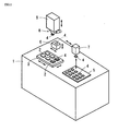
- Fig. 1 illustrates the overall configuration of a bonding apparatus having an ultrasonic bonding head according to the present invention.
- an apparatus frame 1 of this bonding apparatus Arranged on the upper face of an apparatus frame 1 of this bonding apparatus is a mounting stage 3 where boards 2, serving as an example of objects to be bonded to, are loaded and held, and a parts supply 5 where parts 4 such as chip parts with bumps, serving as an example of objects to be bonded, are arrayed and stored.
- a parts transporting stage 6 Provided above the apparatus frame 1 is a parts transporting stage 6, a parts supply unit 7 for supplying parts 4 retrieved from the parts supply 5 to the parts transporting stage 6, an ultrasonic bonding head 8 for taking the part 4 supplied to the parts transporting stage 6 and bonding the part 4 to the board 2 on the mounting stage 3, and an elevating block 9 for ascending or descending while supporting the ultrasonic bonding head 8.
- the mounting stage 3 is configured to be capable of moving horizontally forwards and backwards, and to the left and right, in order to be positioned for parts 4 held by the ultrasonic bonding head 8.
- the parts transporting stage 6 is configured to be capable of moving vertically and horizontally, to transport the parts 4 supplied by the parts supplying unit 7 to the vertical moving path of the ultrasonic bonding head 8, and hand the parts 4 to the ultrasonic bonding head 8.
- Fig. 2 illustrates an example of a specific configuration of the elevating block 9.
- the elevating block 9 comprises a base 40, an elevating device 41 made up of a servo motor fixed to the base 40, a slide plate 43 attached to the base 40 so as to be vertically movable by a guide 42, a load applying device 30 formed of an air cylinder fixed to the slide plate 43, as well as other members.
- the rotating shaft of the elevating device 41 is configured of a screw shaft 41a, with the screw shaft 41a being screwed to a nut portion (not shown) provided to the slide plate 43.
- the load applying device 30 has a piston rod 31, and a pressing jig 32 is fixed on the bottom end of the piston rod 31. As described later, the pressing jig 32 is linked to a connecting portion 18 of the ultrasonic horn 10A. Supplying pressurized air to one chamber 30a of the load applying device 30 via tubing 44 produces a downwards pressing load to the ultrasonic horn 10A via the piston rod 31. On the other hand, the air existing on the other chamber 30b can be discharged via the tubing 45.
- Springs 46 serving as load cancelers for the ultrasonic horn 10A are strung between the slide plate 43 and the pressing jig 32. Accordingly, the weight of the ultrasonic horn 10A itself does not act as the pressing weight applied on the objects to be bonded (i.e., the part 4 and board 2) from the ultrasonic horn 10A, so that this pressing weight can be adjusted by the air pressure supplied to the chamber 30a of the load applying device 30 alone.
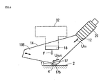
- Figs. 3 and 4 illustrate a detailed configuration of a first embodiment of the ultrasonic bonding head 8.
- This ultrasonic bonding head 8 bonds a part 4 with bumps to a board 2 as described above, by applying a pressing load and ultrasonic vibrations, and comprises an ultrasonic horn 10A.
- the main unit of the ultrasonic horn 10A is a block-shaped member integrally formed in the shape of an inverted isosceles triangle, which made of metal material such as an aluminum alloy, refractory metal, titanium alloy, stainless steel, or the like.
- the ultrasonic horn 10A has a lower apex 11 and left and right apexes 12 and 13, with cut faces being formed at the lower apex 11 and the left and right apexes 12 and 13.
- the cut face on the lower apex 11 is perpendicular to a horizontal symmetry axis CL, and in this case is parallel to the upper side 14.
- the cut faces of the left and right apexes 12 and 13 are perpendicular to the direction of facing the lower apex 11, and in this case, are approximately perpendicular to the hypotenuses 15 and 16, respectively.
- the apex angle ⁇ at the lower apex 11 in the present embodiment is within the range of 60° to 150°, and more preferably within the range of 90° to 120°.
- An abutting member 17 formed of a wear-resistant material (e.g., refractory metal, ceramic, diamond, etc.) is detachably fixed to the cut face of the lower apex 11 of the ultrasonic horn 10A.
- the face of contact 17b between the abutting member 17 and the part 4 is a flat face finished to have a desired surface coarseness, with a suction hole 17a for applying suction to the part 4 being formed in the abutting member 17.
- This suction hole 17a communicates with a suction hole 10a provided to the ultrasonic horn 10A, and the top of the suction hole 10a is connected with a vacuum suctioning device (not shown) via vacuum tubing 47 shown in Fig. 2.
- the vacuum tubing 47 is preferably a hose formed of a resilient material.
- a piezoelectric vibrator 20 is fixed to the cut face of one of the apexes (the right apex 12 in this case) of the ultrasonic horn 10A, to provide ultrasonic vibrations to the right apex 12 of the ultrasonic horn 10A in a direction facing the lower apex 11.
- the cut face of the right apex 12 is approximately perpendicular to the hypotenuse 15, so the direction of vibrations is almost parallel with the hypotenuse 15.
- the angle between the direction of vibrations and the hypotenuse 15 may be around ⁇ 10°.
- a vibration frequency within the range of 20 kHz to 200 kHz is preferable. 60 kHz was used in this case.
- flange-shaped connecting portions 18 are erected on both front and back sides of the ultrasonic horn 10A, around the center of the upper side 14 facing the lower apex 11 and somewhat lower than the upper side 14.
- the piston rod 31 (Fig. 2) of the load applying device 30 is linked to the connecting portions 18 by the pressing jig 32.
- the pressing jig 32 has two legs 32a protruding downwards, with the legs 32a being fixed to the connecting portions 18 by tightening devices 33 such as bolts or the like. Accordingly, the pressing jig 32 comes in contact with no portions of the ultrasonic horn 10A other than the connecting portions 18.
- Fig. 5A is a displacement vector diagram
- Fig. 5B is a displacement contour diagram
- the amplitude of the output vibrations Uout at the lower apex 11 is greater in amplitude than the input vibrations Uin at the right apex 12. This means that the vibrations of the ultrasonic vibrations Uin input from the right apex 12 are amplified and great ultrasonic vibrations Uout are output from the lower apex 11.
- a region where vibrations are small exists in an arc-shaped area passing approximately through the middle of the hypotenuses 15 and 16 of the ultrasonic horn 10A.
- a minimal vibration region exists somewhat below the center portion of the upper side 14 facing the lower apex 11, on or near the symmetry axis CL.
- Connecting portions 18 provided within the node region are used as load applying portions, so connecting the load applying device 30 (pressing jig 32) to the connecting portions 18 enables an arrangement wherein there is no propagation of ultrasonic vibrations to the load applying device 30 from the connecting portions 18, and accordingly there is no disturbance of the vibration. Also, as shown in Fig.
- applying a downward pressing load F with the load applying device 30 means that the vector of the pressing load F passes through the lower apex 11, so there is no flexing of the ultrasonic horn 10A, and the pressing load F can be placed directly upon the lower apex 11.
- the portion for linking the load applying device 30 does not need to be restricted to the above-described minimal vibration region. Approximately the same advantages can be obtained by linking the load applying device 30 in the above-described arc-shaped area where vibrations are small, at a position where the total vector of the pressing load F passes through the lower apex 11.
- the ultrasonic horn 10A is horizontally symmetrical, the same advantages are obtained regardless whether the input portion for the ultrasonic vibrations is the apex 12 or the apex 13.
- Fig. 6 illustrates a second embodiment of the ultrasonic bonding head according to the present invention.
- This embodiment is an arrangement wherein an ultrasonic horn 10B, having the same form as the ultrasonic horn 10A in the first embodiment, is tilted as to the bonding face, and the abutting member 17 is formed with a chevron shape so that the contact face 17b with the object to be bonded 4 is parallel with the bonding face.
- connecting portions 18 provided to the ultrasonic horn 10B are tilted as to the upper side 14 so as to be fixed parallel with the bonding face.
- ultrasonic vibrations Uout in the diagonal direction as indicated by the arrow are output to the lower apex 11 serving as the output portion, so the abutting member 17 provides diagonal vibrations to the object to be bonded 4.
- Tilting the ultrasonic horn 10B thus and adjusting the angle of the contact face 17b of the abutting member 17 allows setting of an arbitrary ratio of the components of the ultrasonic vibrations applied to the object to be bonded 4 that are parallel to the bonding face and the vertical components thereof. Accordingly, bonding can be optimized for a wide variety of materials.
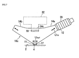
- Fig. 7 illustrates a third embodiment of the ultrasonic bonding head according to the present invention.
- This embodiment is an arrangement wherein the upper side 14 of an ultrasonic horn 10C is formed in a recessed shape, having two inclined faces 14a and 14b, and a base 14c.
- Other configurations are the same as those described with the first embodiment (see Fig. 4), so these components will be denoted with the same reference numerals and redundant description will be omitted.
- Fig. 8A is a displacement vector diagram of the ultrasonic horn 10C
- Fig. 8B is a displacement contour diagram thereof.
- Figs. 8A and 8B upon ultrasonic vibrations being input to one of the apexes 12 and 13, toward the lower apex 11, only horizontal ultrasonic vibrations (100% horizontal vibration component and 0% vertical vibration component), are output to the lower apex 11. Moreover, the output vibrations are greater than the input vibrations.
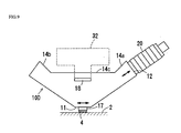
- Fig. 9 illustrates a fourth embodiment of the ultrasonic bonding head according to the present invention.
- This embodiment is a modification of the third embodiment, wherein the upper side 14 of an ultrasonic horn 10D is formed in a recessed shape, having two inclined faces 14a and 14b, and a base 14c, wherein the angle of the inclined faces 14a and 14b is steeper as compared to the third embodiment, and the base 14c is broader.
- Fig. 10 illustrates a fifth embodiment of the ultrasonic bonding head according to the present invention.
- This embodiment is an arrangement wherein the upper side 14 of an ultrasonic horn 10E is formed in a V-shape, having two inclined faces 14a and 14b.
- This arrangement has no horizontal face on the upper side 14, so the direction of the ultrasonic vibrations output from the output portion are not parallel with the upper side 14, but rather perpendicular to the horizontal symmetry axis of the horn main unit.
- Fig. 11 illustrates a sixth embodiment of the ultrasonic bonding head according to the present invention.
- This embodiment is an arrangement wherein the upper side 14 of an ultrasonic horn 10F is formed in a convex raised shape, having two inclined faces 14d and 14e, and a top face 14f.
- the displacement distribution of vibrations can be adjusted to a desired displacement distribution by changing the shape of the upper side 14 of the ultrasonic horn 10C through 10F.
- Fig. 12 illustrates a seventh embodiment of the ultrasonic bonding head according to the present invention.
- This embodiment is an arrangement wherein the hypotenuses 15a and 16b of an ultrasonic horn 10G are formed bending concavely upwards, rather than being flat.
- the displacement distribution of vibrations can be adjusted in the same way as changing the shape of the upper side 14.
- ultrasonic horn 10G is not symmetrical in the strictest sense, with this embodiment, advantages the same as the ultrasonic horns 10A through 10F in the first through sixth embodiments can be obtained.
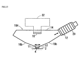
- Fig. 13 illustrates an eighth embodiment of the ultrasonic bonding head according to the present invention.
- This embodiment is an arrangement wherein the hypotenuses 15b and 16b of an ultrasonic horn 10H are formed bending convexly downwards. In this case as well, the displacement distribution of vibrations can be adjusted. Also, this ultrasonic horn 10H is not symmetrical in the strictest sense.
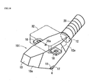
- Fig. 14 illustrates a ninth embodiment of the ultrasonic bonding head according to the present invention.
- This embodiment is an arrangement wherein the thickness of the center portion of an ultrasonic horn 10I including the lower apex 11 is increased progressively with respect to the thickness of both end portions including the left and right apexes 12 and 13, by providing inclined faces 12a and 13b therebetween.
- the amplitude is smaller since the thickness of the lower apex 11 where the ultrasonic vibrations Uout are output is greater than the thickness of the right apex 12 where the ultrasonic vibrations Uin are input, but the driving force is greater.
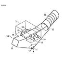
- Fig. 15 illustrates a tenth embodiment of the ultrasonic bonding head according to the present invention.
- This embodiment is an arrangement wherein the thickness of the center portion of an ultrasonic horn 10J including the lower apex 11 is greater than the thickness of both end portions including the left and right apexes 12 and 13, by providing stepped portions 12b and 13b therebetween.
- the amplitude is smaller since the thickness of the lower apex 11 where the ultrasonic vibrations Uout are output is greater than that of the right apex 12 where the ultrasonic vibrations Uin are input, but the driving force is greater, as with the ninth embodiment.
- Fig. 16 illustrates an eleventh embodiment of the ultrasonic bonding head according to the present invention.
- This embodiment is an arrangement wherein the upper side 14 of an ultrasonic horn 10K is formed in a recessed shape, having two inclined faces 14a and 14b, and a base 14c, as with the third embodiment (see Fig. 8), with the connecting portions 18 each comprising two rods protruding from the sides of the ultrasonic horn 10K.
- the vibration node point divides into two regions. Providing the connecting portions 18 to each of the node points allows the pressing load to be applied to the node points alone, thus stabilizing the vibration properties. This arrangement is easy to manufacture and costs can be reduced.
- the upper face 14 of the ultrasonic horn 10K may be a flat face as with the first embodiment, or a raised shape as with the sixth embodiment.
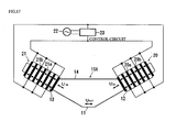
- Fig. 17 illustrates a twelfth embodiment of the ultrasonic bonding head according to the present invention.
- This embodiment is an arrangement wherein vibrators 20 and 21 are attached to both the left and right apexes 12 and 13 of the ultrasonic horn 10A.
- the vibrators 20 and 21 have a known configuration wherein multiple piezoelectric devices 20a and 21a are alternated with multiple electrode plates 20b and 21b, with the piezoelectric devices 20a and 21a being polarized in the thickness direction thereof as indicated by the arrows.
- the vibrators 20 and 21 are configured so that the ultrasonic vibration phases generated thereby are opposite.
- the polarization directions of the piezoelectric devices 20a and 21a making up the vibrators 20 and 21 are reverse, and the electrode plates 20b and 21b are connected to a power source 22 in parallel.
- Reference numeral 23 denotes a control circuit for controlling the vibrators 20 and 21.
- the phases of the ultrasonic vibrations input to the left and right apexes 12 and 13 are opposite, so ultrasonic vibrations with a greater driving force can be output from the lower apex 11 as compared to an arrangement wherein the ultrasonic vibrations are input to only one of the left and right apexes 12 and 13.
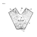
- Fig. 18 illustrates a thirteenth embodiment of the ultrasonic horn according to the present invention.
- This embodiment is an arrangement wherein the apex angle ⁇ of the lower apex 11 of the ultrasonic horn 10L is 60°, and the overall shape is V-shaped.
- the displacement vectors in Fig. 18 upon ultrasonic vibrations toward the lower apex 11 being input from at least one of the left and right apexes 12 and 13, only horizontal ultrasonic vibrations (100% horizontal vibration component and 0% vertical vibration component) are output to the lower apex 11.
- Fig. 19 illustrates a fourteenth embodiment of the ultrasonic horn according to the present invention.
- This embodiment is an arrangement wherein the apex angle ⁇ of the lower apex 11 of the ultrasonic horn 10M is 150°.
- the displacement vectors in Fig. 19 upon ultrasonic vibrations being input toward the lower apex 11 from at least one of the left and right apexes 12 and 13, only horizontal ultrasonic vibrations are output to the lower apex 11.
- the present invention can also be used for bonding chips having multiple leads to a tape, called TAB, and for bonding metal to metal. That is to say, the present invention can be applied to all apparatuses in which metal is bonded to metal using ultrasonic vibrations.
- ultrasonic bonding apparatuses perform bonding by applying ultrasonic vibrations and a pressing load
- heat may be applied as well.
- a heating device for heating the ultrasonic horn and mounting stage is added.
- the lower apex does not need to be directly brought into contact with the object to be bonded.
- a horizontal cut face is provided to the lower apex in the embodiments, this type of cut face is not indispensable, and the lower apex may be of an arbitrary shape.
- the elevating device 41 may serve as the load applying device 30.
- the present invention also has the following advantages, as has been made clear through the embodiments.
- the lower apex of the ultrasonic horn which directly or indirectly comes into contact with the object to be bonded, protrudes downwards, so bonding can be carried out without interfering with obstacles (other parts, etc.) which may be present around the bonding face.
Landscapes
- Engineering & Computer Science (AREA)
- Mechanical Engineering (AREA)
- Manufacturing & Machinery (AREA)
- Microelectronics & Electronic Packaging (AREA)
- Apparatuses For Generation Of Mechanical Vibrations (AREA)
- Pressure Welding/Diffusion-Bonding (AREA)
- Wire Bonding (AREA)
Applications Claiming Priority (4)
| Application Number | Priority Date | Filing Date | Title |
|---|---|---|---|
| JP2002047480 | 2002-02-25 | ||
| JP2002047480 | 2002-02-25 | ||
| JP2003024479A JP3952959B2 (ja) | 2002-02-25 | 2003-01-31 | 超音波ホーンおよびこの超音波ホーンを用いた超音波接合装置 |
| JP2003024479 | 2003-01-31 |
Publications (2)
| Publication Number | Publication Date |
|---|---|
| EP1339096A2 true EP1339096A2 (de) | 2003-08-27 |
| EP1339096A3 EP1339096A3 (de) | 2008-02-13 |
Family
ID=27667557
Family Applications (1)
| Application Number | Title | Priority Date | Filing Date |
|---|---|---|---|
| EP03004098A Withdrawn EP1339096A3 (de) | 2002-02-25 | 2003-02-25 | Ultraschalhorn und Ultraschalbondvorrichtung, die das Ultraschalhorn verwendet |
Country Status (4)
| Country | Link |
|---|---|
| US (1) | US6877648B2 (de) |
| EP (1) | EP1339096A3 (de) |
| JP (1) | JP3952959B2 (de) |
| CN (1) | CN1241245C (de) |
Cited By (7)
| Publication number | Priority date | Publication date | Assignee | Title |
|---|---|---|---|---|
| EP1785213A3 (de) * | 2005-11-09 | 2009-05-27 | Semikron Elektronik GmbH & Co. KG Patentabteilung | Ultraschallschweißkopf |
| CN102669920A (zh) * | 2011-03-17 | 2012-09-19 | Ems专利股份公司 | 套壳体 |
| US9109115B2 (en) | 2013-03-15 | 2015-08-18 | Ems-Patent Ag | Polyamide moulding compound and moulded articles produced herefrom |
| WO2015169603A1 (de) * | 2014-05-05 | 2015-11-12 | Ev Group E. Thallner Gmbh | Verfahren und vorrichtung zum permanenten bonden |
| US9453106B2 (en) | 2012-05-23 | 2016-09-27 | Ems-Patent Ag | Scratch-resistant, transparent and tough copolyamide moulding compounds, moulded articles produced therefrom and uses thereof |
| US9963591B2 (en) | 2012-12-18 | 2018-05-08 | Ems-Patent Ag | Polyamide molding material and moldings manufactured from same |
| CN111590905A (zh) * | 2020-05-29 | 2020-08-28 | 方需科技(上海)有限公司 | 一种手持式超声波点焊机及操作方法 |
Families Citing this family (37)
| Publication number | Priority date | Publication date | Assignee | Title |
|---|---|---|---|---|
| JP3765778B2 (ja) * | 2002-08-29 | 2006-04-12 | ローム株式会社 | ワイヤボンディング用キャピラリ及びこれを用いたワイヤボンディング方法 |
| JP3855973B2 (ja) * | 2002-08-29 | 2006-12-13 | 株式会社村田製作所 | 超音波接合方法および超音波接合装置 |
| US20050127144A1 (en) * | 2003-12-10 | 2005-06-16 | Atuhito Mochida | Method of mounting a semiconductor laser component on a submount |
| WO2005117095A1 (ja) * | 2004-05-25 | 2005-12-08 | Murata Manufacturing Co., Ltd. | 超音波接合方法および超音波接合装置 |
| JP2006135249A (ja) * | 2004-11-09 | 2006-05-25 | Fujitsu Ltd | 超音波実装方法およびこれに用いる超音波実装装置 |
| JP4539678B2 (ja) * | 2007-04-25 | 2010-09-08 | パナソニック株式会社 | 電子部品実装方法 |
| KR20100014316A (ko) * | 2007-04-27 | 2010-02-10 | 파나소닉 주식회사 | 전자 부품 장착 장치 및 전자 부품 장착 방법 |
| JP4336732B1 (ja) * | 2008-04-11 | 2009-09-30 | Tdk株式会社 | 超音波実装装置 |
| JP4564548B2 (ja) * | 2008-04-28 | 2010-10-20 | 株式会社アルテクス | 超音波振動接合用共振器とそれを支持する支持装置 |
| JP5313751B2 (ja) * | 2008-05-07 | 2013-10-09 | パナソニック株式会社 | 電子部品装着装置 |
| JP5491081B2 (ja) * | 2009-06-22 | 2014-05-14 | 株式会社アルテクス | 超音波振動金属接合用共振器 |
| US8113411B2 (en) * | 2010-03-30 | 2012-02-14 | Flextronics Ap, Llc | Universal radio frequency shield removal |
| DE112011101129B4 (de) | 2010-03-31 | 2022-05-25 | Kulicke And Soffa Industries, Inc. | Ultraschall-Bondsysteme und Verfahren zu ihrer Verwendung |
| US8746537B2 (en) | 2010-03-31 | 2014-06-10 | Orthodyne Electronics Corporation | Ultrasonic bonding systems and methods of using the same |
| US8231044B2 (en) | 2010-10-01 | 2012-07-31 | Orthodyne Electronics Corporation | Solar substrate ribbon bonding system |
| US8196798B2 (en) | 2010-10-08 | 2012-06-12 | Kulicke And Soffa Industries, Inc. | Solar substrate ribbon bonding system |
| US9010827B2 (en) | 2011-11-18 | 2015-04-21 | Nike, Inc. | Switchable plate manufacturing vacuum tool |
| US8858744B2 (en) | 2011-11-18 | 2014-10-14 | Nike, Inc. | Multi-functional manufacturing tool |
| US9451810B2 (en) | 2011-11-18 | 2016-09-27 | Nike, Inc. | Automated identification of shoe parts |
| US8958901B2 (en) | 2011-11-18 | 2015-02-17 | Nike, Inc. | Automated manufacturing of shoe parts |
| US8755925B2 (en) | 2011-11-18 | 2014-06-17 | Nike, Inc. | Automated identification and assembly of shoe parts |
| US8960745B2 (en) | 2011-11-18 | 2015-02-24 | Nike, Inc | Zoned activation manufacturing vacuum tool |
| US10552551B2 (en) | 2011-11-18 | 2020-02-04 | Nike, Inc. | Generation of tool paths for shore assembly |
| US8849620B2 (en) | 2011-11-18 | 2014-09-30 | Nike, Inc. | Automated 3-D modeling of shoe parts |
| US8696043B2 (en) | 2011-11-18 | 2014-04-15 | Nike, Inc. | Hybrid pickup tool |
| US20130240152A1 (en) * | 2012-03-15 | 2013-09-19 | Nike, Inc. | Hollow tip welding tool |
| CN102699518B (zh) * | 2012-06-25 | 2015-02-25 | 雷广伟 | 一种动力电池电极超声波连续滚动焊接装置及其工作方法 |
| CN104508776A (zh) * | 2012-08-03 | 2015-04-08 | 株式会社村田制作所 | 电子设备的制造方法 |
| KR102073189B1 (ko) * | 2013-04-04 | 2020-02-04 | 삼성에스디아이 주식회사 | 이차전지용 용접혼 |
| JP6218669B2 (ja) * | 2014-05-13 | 2017-10-25 | 東洋自動機株式会社 | エアバッグ付き袋への気体封入方法及び気体封入装置 |
| WO2017000998A1 (de) * | 2015-06-30 | 2017-01-05 | Telsonic Holding Ag | Vorrichtung zum verschweissen von bauteilen mittels ultraschalls durch torsionschwingungen |
| CN108857037B (zh) * | 2018-08-03 | 2024-01-26 | 辽宁工业大学 | 一种兆赫级高频超声波焊接装置及其方法 |
| US11697172B2 (en) * | 2019-09-05 | 2023-07-11 | Ohio State Innovation Foundation | Systems and methods for joining and repair using ultrasonic additive manufacturing with a contoured sonotrode |
| CN110662145B (zh) * | 2019-10-14 | 2021-05-11 | 陕西师范大学 | 一种正弦阶梯喇叭形声换能器及换能方法 |
| CN112091470B (zh) * | 2020-10-30 | 2021-03-16 | 广州松合智能科技有限公司 | 一种不锈钢外壳焊接全自动焊接设备 |
| DE102023110696A1 (de) | 2023-04-26 | 2024-10-31 | Pac Tech - Packaging Technologies Gmbh | Bondkopf und Bondvorrichtung |
| DE102024208585A1 (de) | 2024-09-10 | 2026-03-12 | Infineon Technologies Ag | SONOTRODE FÜR EINE ULTRASCHALLSCHWEIßVORRICHTUNG, VERFAHREN ZUM SCHWEIßEN EINES WERKSTÜCKS AN EIN LEISTUNGSELEKTRONISCHES SUBSTRAT, VERFAHREN ZUR OBERFLÄCHENBEHANDLUNG EINER SONOTRODE FÜR EINE ULTRASCHALLSCHWEIßVORRICHTUNG UND HALBLEITERGEHÄUSE |
Citations (2)
| Publication number | Priority date | Publication date | Assignee | Title |
|---|---|---|---|---|
| JP2001044242A (ja) | 1999-07-26 | 2001-02-16 | Matsushita Electric Ind Co Ltd | フリップチップ実装装置及び方法 |
| JP2001110850A (ja) | 1999-10-12 | 2001-04-20 | Matsushita Electric Ind Co Ltd | フリップチップ実装装置、及び方法 |
Family Cites Families (18)
| Publication number | Priority date | Publication date | Assignee | Title |
|---|---|---|---|---|
| US3039333A (en) * | 1958-06-03 | 1962-06-19 | Aeroprojects Inc | Apparatus for introducing high levels of vibratory energy to a work area |
| US3148293A (en) * | 1961-06-05 | 1964-09-08 | Aeroprojects Inc | Vibratory device for delivering vibratory energy at high power |
| DE2708226A1 (de) * | 1977-02-25 | 1978-08-31 | Siemens Ag | Sende- und empfangswandler fuer ultraschall-strahlung, geeignet fuer grossen entfernungsbereich |
| US5645681B1 (en) * | 1996-07-05 | 2000-03-14 | Minnesota Mining & Mfg | Stacked rotary acoustic horn |
| JPH10236439A (ja) * | 1997-02-26 | 1998-09-08 | Sony Corp | パッケージ用ケース及びその超音波溶着方法 |
| US6078125A (en) * | 1997-07-22 | 2000-06-20 | Branson Ultrasonics Corp. | Ultrasonic apparatus |
| JP3409689B2 (ja) * | 1998-04-21 | 2003-05-26 | 松下電器産業株式会社 | 電子部品のボンディングツールおよびボンディング装置 |
| JP4016513B2 (ja) * | 1998-12-10 | 2007-12-05 | 松下電器産業株式会社 | 電子部品のボンディングツールおよび電子部品のボンディングツールの吸着部、電子部品のボンディング装置 |
| JP3557940B2 (ja) * | 1999-03-05 | 2004-08-25 | 松下電器産業株式会社 | 電子部品のボンディングツールおよびボンディング装置 |
| US6244498B1 (en) * | 1999-04-16 | 2001-06-12 | Micron Semiconductor, Inc. | Ultrasonic vibration mode for wire bonding |
| JP3373810B2 (ja) | 1999-08-02 | 2003-02-04 | 株式会社アルテクス | 超音波振動接合用超音波ホーン |
| TW460345B (en) * | 1999-08-02 | 2001-10-21 | Arutekusu Kk | Joining device by ultrasonic vibration |
| JP3525866B2 (ja) * | 2000-06-30 | 2004-05-10 | 松下電器産業株式会社 | 電子部品のボンディング装置およびボンディングツール |
| JP4572484B2 (ja) | 2001-05-09 | 2010-11-04 | 株式会社村田製作所 | 超音波ボンディング装置 |
| JP3466175B2 (ja) * | 2001-12-03 | 2003-11-10 | 三島 大二 | 超音波振動ホーン |
| DE10160228A1 (de) * | 2001-12-07 | 2003-06-18 | Hesse & Knipps Gmbh | Kreuztransducer |
| JP3788351B2 (ja) * | 2002-01-21 | 2006-06-21 | 松下電器産業株式会社 | 電子部品のボンディング装置および電子部品のボンディングツール |
| JP3855973B2 (ja) * | 2002-08-29 | 2006-12-13 | 株式会社村田製作所 | 超音波接合方法および超音波接合装置 |
-
2003
- 2003-01-31 JP JP2003024479A patent/JP3952959B2/ja not_active Expired - Lifetime
- 2003-02-24 US US10/372,372 patent/US6877648B2/en not_active Expired - Lifetime
- 2003-02-25 CN CNB031066526A patent/CN1241245C/zh not_active Expired - Lifetime
- 2003-02-25 EP EP03004098A patent/EP1339096A3/de not_active Withdrawn
Patent Citations (2)
| Publication number | Priority date | Publication date | Assignee | Title |
|---|---|---|---|---|
| JP2001044242A (ja) | 1999-07-26 | 2001-02-16 | Matsushita Electric Ind Co Ltd | フリップチップ実装装置及び方法 |
| JP2001110850A (ja) | 1999-10-12 | 2001-04-20 | Matsushita Electric Ind Co Ltd | フリップチップ実装装置、及び方法 |
Cited By (11)
| Publication number | Priority date | Publication date | Assignee | Title |
|---|---|---|---|---|
| EP1785213A3 (de) * | 2005-11-09 | 2009-05-27 | Semikron Elektronik GmbH & Co. KG Patentabteilung | Ultraschallschweißkopf |
| CN102669920A (zh) * | 2011-03-17 | 2012-09-19 | Ems专利股份公司 | 套壳体 |
| CN102669920B (zh) * | 2011-03-17 | 2016-05-25 | Ems专利股份公司 | 套壳体 |
| US9453106B2 (en) | 2012-05-23 | 2016-09-27 | Ems-Patent Ag | Scratch-resistant, transparent and tough copolyamide moulding compounds, moulded articles produced therefrom and uses thereof |
| US9963591B2 (en) | 2012-12-18 | 2018-05-08 | Ems-Patent Ag | Polyamide molding material and moldings manufactured from same |
| US9109115B2 (en) | 2013-03-15 | 2015-08-18 | Ems-Patent Ag | Polyamide moulding compound and moulded articles produced herefrom |
| WO2015169603A1 (de) * | 2014-05-05 | 2015-11-12 | Ev Group E. Thallner Gmbh | Verfahren und vorrichtung zum permanenten bonden |
| CN106415811A (zh) * | 2014-05-05 | 2017-02-15 | Ev 集团 E·索尔纳有限责任公司 | 用于永久接合的方法和装置 |
| US9947638B2 (en) | 2014-05-05 | 2018-04-17 | Ev Group E. Thallner Gmbh | Device and method for permanent bonding |
| CN106415811B (zh) * | 2014-05-05 | 2019-05-17 | Ev 集团 E·索尔纳有限责任公司 | 用于永久接合的方法和装置 |
| CN111590905A (zh) * | 2020-05-29 | 2020-08-28 | 方需科技(上海)有限公司 | 一种手持式超声波点焊机及操作方法 |
Also Published As
| Publication number | Publication date |
|---|---|
| US6877648B2 (en) | 2005-04-12 |
| EP1339096A3 (de) | 2008-02-13 |
| JP2003318230A (ja) | 2003-11-07 |
| US20030160084A1 (en) | 2003-08-28 |
| JP3952959B2 (ja) | 2007-08-01 |
| CN1441475A (zh) | 2003-09-10 |
| CN1241245C (zh) | 2006-02-08 |
Similar Documents
| Publication | Publication Date | Title |
|---|---|---|
| US6877648B2 (en) | Ultrasonic horn, and ultrasonic bonding apparatus using the ultrasonic horn | |
| US7017791B2 (en) | Ultrasonic bonding method and device | |
| US6743331B2 (en) | Component bonder and bonding tool | |
| US5385288A (en) | Bonding apparatus | |
| JP2004327590A (ja) | ボンディング装置およびボンディングツール | |
| JP3541354B2 (ja) | 超音波振動接合装置 | |
| JP3932286B2 (ja) | ボンディングヘッドおよびこれを備えたボンディング装置 | |
| JP3487162B2 (ja) | ボンディングツールおよびボンディング装置 | |
| US7508115B2 (en) | Horn, horn unit, and bonding apparatus using same | |
| JP3882792B2 (ja) | 接合装置および接合用ツール | |
| Tsujino et al. | Welding characteristics of ultrasonic wire bonding using high-frequency vibration systems | |
| JP4345815B2 (ja) | 超音波接合方法および超音波接合装置 | |
| JP2001176932A (ja) | 超音波振動体 | |
| JP2003059972A (ja) | ボンディングヘッド及びこれを備えたボンディング装置 | |
| JP2000174069A (ja) | 電子部品のボンディングツールおよびボンディング装置 | |
| JP2002334909A (ja) | 超音波振動接合用共振器 | |
| JP3480468B2 (ja) | 電子部品のボンディングツール | |
| JP3866150B2 (ja) | ボンディングヘッド及びこれを備えたボンディング装置 | |
| JP3491634B2 (ja) | 電子部品のボンディングツール | |
| JP4301246B2 (ja) | 電子部品のボンディング装置および電子部品のボンディングツール | |
| JP2002343831A (ja) | ボンディングヘッド及びこれを備えたボンディング装置 | |
| JP3374853B2 (ja) | 電子部品のボンディングツール | |
| JP2004165548A (ja) | ボンディング装置およびボンディングツール | |
| JP2007288220A (ja) | 電子部品のボンディングツールおよび電子部品のボンディング装置 | |
| JP2001097531A (ja) | 物体浮揚方法、荷取り方法及び物体搬送方法並びに物体浮揚装置及び荷取り装置 |
Legal Events
| Date | Code | Title | Description |
|---|---|---|---|
| PUAI | Public reference made under article 153(3) epc to a published international application that has entered the european phase |
Free format text: ORIGINAL CODE: 0009012 |
|
| 17P | Request for examination filed |
Effective date: 20030225 |
|
| AK | Designated contracting states |
Designated state(s): AT BE BG CH CY CZ DE DK EE ES FI FR GB GR HU IE IT LI LU MC NL PT SE SI SK TR |
|
| AX | Request for extension of the european patent |
Extension state: AL LT LV MK RO |
|
| RAP1 | Party data changed (applicant data changed or rights of an application transferred) |
Owner name: MURATA MANUFACTURING CO., LTD. |
|
| PUAL | Search report despatched |
Free format text: ORIGINAL CODE: 0009013 |
|
| AK | Designated contracting states |
Kind code of ref document: A3 Designated state(s): AT BE BG CH CY CZ DE DK EE ES FI FR GB GR HU IE IT LI LU MC NL PT SE SI SK TR |
|
| AX | Request for extension of the european patent |
Extension state: AL LT LV MK RO |
|
| AKX | Designation fees paid |
Designated state(s): DE FR GB |
|
| 17Q | First examination report despatched |
Effective date: 20081010 |
|
| STAA | Information on the status of an ep patent application or granted ep patent |
Free format text: STATUS: THE APPLICATION IS DEEMED TO BE WITHDRAWN |
|
| 18D | Application deemed to be withdrawn |
Effective date: 20170901 |
|
| RIC1 | Information provided on ipc code assigned before grant |
Ipc: H01L 21/00 20060101AFI20030708BHEP |