EP1339261A2 - Beheizbare Leitung - Google Patents
Beheizbare Leitung Download PDFInfo
- Publication number
- EP1339261A2 EP1339261A2 EP03004101A EP03004101A EP1339261A2 EP 1339261 A2 EP1339261 A2 EP 1339261A2 EP 03004101 A EP03004101 A EP 03004101A EP 03004101 A EP03004101 A EP 03004101A EP 1339261 A2 EP1339261 A2 EP 1339261A2
- Authority
- EP
- European Patent Office
- Prior art keywords
- tube
- heating device
- temperature
- connecting piece
- line according
- Prior art date
- Legal status (The legal status is an assumption and is not a legal conclusion. Google has not performed a legal analysis and makes no representation as to the accuracy of the status listed.)
- Granted
Links
Images
Classifications
-
- H—ELECTRICITY
- H05—ELECTRIC TECHNIQUES NOT OTHERWISE PROVIDED FOR
- H05B—ELECTRIC HEATING; ELECTRIC LIGHT SOURCES NOT OTHERWISE PROVIDED FOR; CIRCUIT ARRANGEMENTS FOR ELECTRIC LIGHT SOURCES, IN GENERAL
- H05B1/00—Details of electric heating devices
- H05B1/02—Automatic switching arrangements specially adapted to apparatus ; Control of heating devices
- H05B1/0227—Applications
- H05B1/023—Industrial applications
- H05B1/0244—Heating of fluids
-
- F—MECHANICAL ENGINEERING; LIGHTING; HEATING; WEAPONS; BLASTING
- F16—ENGINEERING ELEMENTS AND UNITS; GENERAL MEASURES FOR PRODUCING AND MAINTAINING EFFECTIVE FUNCTIONING OF MACHINES OR INSTALLATIONS; THERMAL INSULATION IN GENERAL
- F16L—PIPES; JOINTS OR FITTINGS FOR PIPES; SUPPORTS FOR PIPES, CABLES OR PROTECTIVE TUBING; MEANS FOR THERMAL INSULATION IN GENERAL
- F16L53/00—Heating of pipes or pipe systems; Cooling of pipes or pipe systems
- F16L53/30—Heating of pipes or pipe systems
- F16L53/35—Ohmic-resistance heating
- F16L53/38—Ohmic-resistance heating using elongate electric heating elements, e.g. wires or ribbons
-
- F—MECHANICAL ENGINEERING; LIGHTING; HEATING; WEAPONS; BLASTING
- F16—ENGINEERING ELEMENTS AND UNITS; GENERAL MEASURES FOR PRODUCING AND MAINTAINING EFFECTIVE FUNCTIONING OF MACHINES OR INSTALLATIONS; THERMAL INSULATION IN GENERAL
- F16L—PIPES; JOINTS OR FITTINGS FOR PIPES; SUPPORTS FOR PIPES, CABLES OR PROTECTIVE TUBING; MEANS FOR THERMAL INSULATION IN GENERAL
- F16L59/00—Thermal insulation in general
- F16L59/14—Arrangements for the insulation of pipes or pipe systems
- F16L59/153—Arrangements for the insulation of pipes or pipe systems for flexible pipes
-
- H—ELECTRICITY
- H05—ELECTRIC TECHNIQUES NOT OTHERWISE PROVIDED FOR
- H05B—ELECTRIC HEATING; ELECTRIC LIGHT SOURCES NOT OTHERWISE PROVIDED FOR; CIRCUIT ARRANGEMENTS FOR ELECTRIC LIGHT SOURCES, IN GENERAL
- H05B3/00—Ohmic-resistance heating
- H05B3/40—Heating elements having the shape of rods or tubes
- H05B3/54—Heating elements having the shape of rods or tubes flexible
- H05B3/56—Heating cables
Definitions
- the invention relates to a heatable line for a tempered flowable Medium, in particular hose line, with a flow path Inner soul, a heating device surrounding the inner soul and one Inner soul with thermal insulation surrounding the heating device.
- Heated lines of the type in question are in the various embodiments known from practice. Only the heatable hose is mentioned below by way of example. This is what it is about usually a flexible hose with a corresponding flexible Inner core, possibly a stainless steel lacing of the inner core, one therefore wound heating conductor, a thermal insulation of the heating conductor Glass fiber fabric and another thermal insulation made of foamed Rubber or the like. To avoid damaging the thermal Insulation made of foamed rubber is therefore usually an outer braid Plastic or the like provided. On both sides of the hose, d. H. to the respective ends, connection caps made of silicone are usually provided, the electrical connection for the heating conductor on one of the connection caps from outside the line. For connection to systems, machines or other lines are usually fittings or connecting nipples or Connection pins provided.
- Heated pipes or heating hoses of the type in question here for example as measuring lines for sample gas measurements, Extruder welding systems, in hot melt adhesive technology, the Food industry, chemical industry, for filling devices, Labeling machines, PU foam spraying systems, oil burner feed lines, Heavy oil lines, etc. used. That within the management or within the Medium to be transported is through the line on a medium to maintain a certain predetermined temperature. According to the application the heat insulation of the heatable line can be very different. So can also multi-layer thermal insulation made of fiberglass and Silicone foam can be provided.
- the present invention is therefore based on the object, the generic To design and develop a heatable line in such a way that it can be easily Effective overheating protection for the item to be transported flowable medium is provided.
- the heatable line for a temperature-controlled fluid medium solves the preceding task by the features of claim 1. Thereafter The heatable line mentioned at the outset is designed and developed in such a way that a heat sensor and / or a in the immediate vicinity of the inner soul Temperature fuse is provided, the or the power supply to the Heating device deactivated when a predetermined temperature is exceeded.
- the heat sensor is used for temperature monitoring - at Exceeding a predetermined temperature - switching off the Heating device.
- a temperature fuse switches the heating device immediately, without the need for separate electronics, namely in that it acts in a conventional manner and directly the The power supply to the heater is interrupted.
- the heating device is in a very particularly advantageous manner an electrical heating conductor that can be easily deactivated by the fact that one cuts off its power supply. This can be done according to the above Executions take place.
- the heat sensor or the temperature fuse could be placed anywhere in be arranged in the immediate vicinity of the inner soul, for which purpose the heat sensor and / or the temperature fuse very easily in the thermal insulation of the heatable line is inserted up to the inner soul. This can be done arbitrary places and at predeterminable intervals using several Heat sensors and / or temperature fuses are carried out.
- the Inner tube on or under the heater, a tube into which the heat sensor or the temperature fuse can be inserted.
- the heat sensor or temperature fuse provided that on the one hand for safe positioning and on the other hand for easy to insert and thus also to replace the heat sensor or is used for temperature protection.
- the pipe runs the entire length of the The inner sensor extends, the heat sensor or the Position the temperature fuse at any point, namely by the dimension of the Pushing into the pipe.
- the tube could be made of be made of a flexible material so that the heatable pipe can be elastically deformed. In the case of a rigid design of the tube or A plastic deformability could be the tube for stiffening and thus contribute to the shaping of the entire heatable line.
- Connect the outwardly extending connector which extends from the pipe at an obtuse angle, preferably in the range between 30 ° and 60 ° Tube, extending outwards.
- the additional thermal insulation can be designed to be removable, so that a Replacement of the heat sensor or the temperature fuse is possible at any time. Insulating measures that can be removed at will are conceivable here.
- the connecting piece could be used as an insertion aid for insertion or Plug in the heat sensor or the temperature fuse as a special Be formed part, which in a particularly advantageous manner from a thermally non or low conductive material is made.
- a plastic connector would be of particular advantage, especially since this is injection molding can be made.
- the connector could be in the insertion opening of the pipe. It is also conceivable to attach the connector to the Put in the insertion opening of the tube, put it on or just accordingly insert.
- the connector As part of a particularly simple design of the heatable line and the overheating protection provided there could make the connector more integral Be part of the pipe.
- Design the connector as a bent end piece of the pipe, so that the pipe with its free - bent - end through the thermal insulation protrudes through to the outside.
- With appropriately designed insertion openings could also connect several connecting pieces over the course of the pipe or be plugged in, for example at predetermined intervals to each other.
- the temperature fuse could act as a temperature monitor or as Bimetal switch can be formed.
- the temperature fuse could be like this be designed so that when a predetermined or predeterminable is exceeded Temperature turns off the heater power supply and at Falling below a predetermined or predeterminable temperature
- the heater power supply is reactivated. Reactivating the Power supply could in turn be based on a predefined or predefinable one Time delay - after switching off the power supply - so that the Checking process takes place again. An effective protection against overheating would be achieved with simple means.
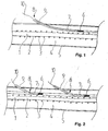
- Fig. 1 shows a first embodiment of a heatable line for a tempered flowable medium, which is shown in the Embodiment is a hose line.
- the flow path 1 becomes formed by an inner core 2, which in the sense of a flexible pipe is executed.
- an inner core 2 which in the sense of a flexible pipe is executed.
- Around this pipeline, one not shown in the figures Braiding to protect the pipeline may be provided or arranged.
- the inner core 2 is directly surrounded by a heating device 3, whereby it specifically an electrical heating conductor.
- the Heating device 3 is wound around the inner core 2, so that over the active heating of the entire length of the inner core 2 Flow path 1 is guaranteed.
- the inner core 2 and the heating device 3 are in turn surrounded by thermal insulation 4.
- thermal insulation 4 To protect the thermal insulation 4 is a braided protective jacket 5 surrounded, this is regularly a mechanical protection is.
- a heat sensor is in the immediate vicinity of the inner core 2 and / or a temperature fuse 6 is provided, with the here selected exemplary embodiments is a temperature fuse 6.
- the Thermal fuse 6 deactivates the one not shown in the figures Power supply to the heating device 3 when a predetermined value is exceeded Temperature, so that a predetermined temperature limit is exceeded is effectively avoided.
- a fuse can be used as a temperature fuse Bimetal switch, a temperature monitor or the like are used.
- FIG Longitudinal direction of the inner core 2 and the heating device 3 is a tube 7, which for Recording the temperature fuse 6 is used. According to the length of the tube 7 the temperature fuse 6 can be positioned anywhere in front of replace everything - in case of a defect.
- FIGS. 1 and 2 show together that the tube 7 has an insertion opening 8 has, which is accessible through the insulation to the outside, so that the Thermal fuse 6 can be inserted into the tube 7 from the outside.
- FIGS. 1 and 2 further show that the insertion opening 8 of the Tube 7 connects an outwardly extending connector 9, which in Range between 30 ° and 60 ° to pipe 7 is bent and accordingly extends outside.
- an outwardly extending connector 9 which in Range between 30 ° and 60 ° to pipe 7 is bent and accordingly extends outside.
- Connector 9 outwardly extending line 10 is the passage through the Connection piece 9 or the insertion opening 8 is thermally insulated, which is shown in the figures is not shown. This thermal insulation allows for free access to the Remove insertion opening 8 or connection piece 9.
- connection piece 9 is a free, bent end of the tube 7 is formed and extends through the thermal insulation 4 through to the outside. This is a whole special design of the tube 7 with integral connecting piece 9.
- connection pieces 9 are provided, which are designed as special moldings and plugged into the insertion openings 8 of the tube 7 or there are set.
Landscapes
- Engineering & Computer Science (AREA)
- General Engineering & Computer Science (AREA)
- Mechanical Engineering (AREA)
- Pipe Accessories (AREA)
- Control Of Resistance Heating (AREA)
- Instantaneous Water Boilers, Portable Hot-Water Supply Apparatuses, And Control Of Portable Hot-Water Supply Apparatuses (AREA)
- Branch Pipes, Bends, And The Like (AREA)
Abstract
Description
- Fig. 1
- in einer schematischen Darstellung ein erstes Ausführungsbeispiel einer erfindungsgemäßen Leitung, wobei dort das Anschlusstück integral als weggebogenes freies Ende des Rohrs ausgebildet ist und
- Fig. 2
- in einer schematischen Darstellung ein zweites Ausführungsbeispiel einer erfindungsgemäßen Leitung, wobei dort das Anschlusstück auf das Rohr unmittelbar an einer Einschuböffnung aufgesteckt ist.
Claims (10)
- Beheizbare Leitung für ein temperiertes strömungsfähiges Medium, insbesondere Schlauchleitung, mit einer einen Strömungspfad (1) bildenden Innenseele (2), einer die Innenseele (2) umgebenden Heizeinrichtung (3) und einer die Innenseele (2) mit der Heizeinrichtung (3) umgebenden thermischen Isolation (4),
dadurch gekennzeichnet, dass in unmittelbarer Nähe der Innenseele (2) ein Wärmesensor und/oder eine Temperatursicherung (6) vorgesehen ist, der bzw. die die Stromversorgung der Heizeinrichtung (3) bei Überschreiten einer vorgegebenen Temperatur deaktiviert. - Leitung nach Anspruch 1, dadurch gekennzeichnet, dass die Heizeinrichtung (3) einen elektrischen Heizleiter umfasst.
- Leitung nach Anspruch 1 oder 2, dadurch gekennzeichnet, dass sich in Längsrichtung der Innenseele (2) auf oder unter der Heizeinrichtung (3) ein Rohr (7) erstreckt, in das der Wärmesensor bzw. die Temperatursicherung (6) einschiebbar ist und/oder dass das Rohr (7) eine Einschuböffnung (8) aufweist, die durch die Isolation (4) hindurch von außen zugänglich ist, so dass der Wärmesensor bzw. die Temperatursicherung (6) von aussen in das Rohr (7) einschiebbar ist und/oder dass sich an die Einschuböffnung (8) des Rohrs (7) ein sich nach außen erstreckendes Anschlusstück (9) anschließt und/oder dass sich das Anschlusstück (9) vom Rohr (7) aus in einem stumpfen Winkel, vorzugsweise im Bereich zwischen 30° und 60° zum Rohr (7), nach außen erstreckt.
- Leitung nach Anspruch 3, dadurch gekennzeichnet, dass bei eingeschobenem Wärmesensor bzw. bei eingeschobener Temperatursicherung (6) und sich durch das Anschlusstück (9) nach aussen erstreckender Leitung (10) der Durchgang durch das Anschlusstück (9) und/oder die Einschuböffnung (8) thermisch isoliert ist bzw. sind, wobei die thermische Isolierung zum freien Zugang der Einschuböffnung (8) entfernbar sein kann.
- Leitung nach Anspruch 3 oder 4, dadurch gekennzeichnet, dass das Anschlusstück (9) als besonderes Formteil ausgebildet ist und/oder aus einem thermisch nicht oder gering leitenden Material hergestellt ist und/oder aus Kunststoff gefertigt ist und/oder spritzgusstechnisch hergestellt ist.
- Leitung nach einem der Ansprüche 3 bis 5, dadurch gekennzeichnet, dass das Anschlusstück (9) in die Einschuböffnung (8) des Rohrs (7) eingesteckt ist und/oder auf die Einschuböffnung (8) des Rohrs (7) aufgesetzt, aufgesteckt oder in die Einschuböffnung (8) eingesteckt ist.
- Leitung nach einem der Ansprüche 3 bis 6, dadurch gekennzeichnet, dass das Anschlusstück (9) integraler Bestandteil des Rohrs (7) ist, wobei das Anschlusstück (9) ein weggebogenes Endstück des Rohrs (7) sein kann.
- Leitung nach einem der Ansprüche 3 bis 7, dadurch gekennzeichnet, dass in vorgegebenen Abständen mindestens zwei Einschuböffnungen (8) mit jeweils einem Anschlusstück (9) vorgesehen sind.
- Leitung nach einem der Ansprüche 1 bis 8, dadurch gekennzeichnet, dass die Temperatursicherung (6) als Temperaturwächter bzw. als Bimetallschalter ausgebildet ist.
- Leitung nach einem der Ansprüche 1 bis 9, dadurch gekennzeichnet, dass die Temperatursicherung (6) derart ausgelegt ist, dass sie bei Überschreiten einer vorgegebenen oder vorgebbaren Temperatur die Stromversorgung der Heizeinrichtung (3) abschaltet und bei Unterschreiten einer vorgegebenen oder vorgebbaren Temperatur die Stromversorgung der Heizeinrichtung (3) wieder aktiviert, wobei die erneute Aktivierung der Stromversorgung nach einer vorgegebenen oder vorgebbaren Zeitverzögerung - nach Abschalten der Stromversorgung - erfolgen kann.
Applications Claiming Priority (2)
| Application Number | Priority Date | Filing Date | Title |
|---|---|---|---|
| DE10207794A DE10207794B4 (de) | 2002-02-25 | 2002-02-25 | Beheizbare Leitung |
| DE10207794 | 2002-02-25 |
Publications (3)
| Publication Number | Publication Date |
|---|---|
| EP1339261A2 true EP1339261A2 (de) | 2003-08-27 |
| EP1339261A3 EP1339261A3 (de) | 2006-10-11 |
| EP1339261B1 EP1339261B1 (de) | 2009-12-23 |
Family
ID=27635271
Family Applications (1)
| Application Number | Title | Priority Date | Filing Date |
|---|---|---|---|
| EP03004101A Expired - Lifetime EP1339261B1 (de) | 2002-02-25 | 2003-02-25 | Beheizbare Leitung |
Country Status (3)
| Country | Link |
|---|---|
| EP (1) | EP1339261B1 (de) |
| AT (1) | ATE453307T1 (de) |
| DE (2) | DE10207794B4 (de) |
Cited By (2)
| Publication number | Priority date | Publication date | Assignee | Title |
|---|---|---|---|---|
| DE102013021506A1 (de) | 2013-12-18 | 2014-06-18 | Daimler Ag | Brennstoffzellensystem und beheizbares Leitungselement |
| DE102013217159B3 (de) * | 2013-08-28 | 2015-01-08 | PSG Petro Service GmbH & Co. KG | Vorrichtung zum Transport eines Mediums |
Families Citing this family (4)
| Publication number | Priority date | Publication date | Assignee | Title |
|---|---|---|---|---|
| DE102012022232A1 (de) | 2012-11-14 | 2014-05-15 | Voss Automotive Gmbh | System enthaltend zumindest eine beheizbare Medienleitung mit zumindest einem Leitungsverbinder, beheizbare Medienleitung zur Verwendung in dem System sowie Verfahren zum Betrieb einer beheizbaren Medienleitung |
| AU2016305122B2 (en) * | 2015-08-10 | 2021-05-13 | National Oilwell Varco Denmark I/S | A method and a system for controlling the temperature of a fluid in an unbonded flexible pipe |
| DE102018117048B4 (de) * | 2018-07-13 | 2021-02-25 | Stemmann-Technik Gmbh | Schlauchtrommelanordnung |
| WO2025056190A1 (de) | 2023-09-14 | 2025-03-20 | Voss Automotive Gmbh | Beheizbare medienleitung, clipelement mit zumindest einer thermischen schutzeinrichtung für eine solche sowie brennstoffzellenfahrzeug mit zumindest einer solchen |
Family Cites Families (4)
| Publication number | Priority date | Publication date | Assignee | Title |
|---|---|---|---|---|
| US3378673A (en) * | 1965-10-18 | 1968-04-16 | Thomas O. Hopper | Electrically heated hose assembly |
| US4455474A (en) * | 1981-11-27 | 1984-06-19 | Nordson Corporation | Thermally insulated electrically heated hose for transmitting hot liquids |
| US5862303A (en) * | 1996-05-17 | 1999-01-19 | Advanced Metal Technologies, Ltd. | Electrically heated pipe with helically wound amorphous alloy heater |
| US5832178A (en) * | 1996-06-25 | 1998-11-03 | Crafco, Incorporated | Hot melt mix applicator with electrically heated hose and wand with temperature-controlled electric generator |
-
2002
- 2002-02-25 DE DE10207794A patent/DE10207794B4/de not_active Expired - Fee Related
-
2003
- 2003-02-25 DE DE50312251T patent/DE50312251D1/de not_active Expired - Lifetime
- 2003-02-25 EP EP03004101A patent/EP1339261B1/de not_active Expired - Lifetime
- 2003-02-25 AT AT03004101T patent/ATE453307T1/de active
Cited By (3)
| Publication number | Priority date | Publication date | Assignee | Title |
|---|---|---|---|---|
| DE102013217159B3 (de) * | 2013-08-28 | 2015-01-08 | PSG Petro Service GmbH & Co. KG | Vorrichtung zum Transport eines Mediums |
| EP2843286A1 (de) | 2013-08-28 | 2015-03-04 | PSG Petro Service GmbH & Co. KG | Vorrichtung zum Transport eines Mediums |
| DE102013021506A1 (de) | 2013-12-18 | 2014-06-18 | Daimler Ag | Brennstoffzellensystem und beheizbares Leitungselement |
Also Published As
| Publication number | Publication date |
|---|---|
| EP1339261B1 (de) | 2009-12-23 |
| DE10207794A1 (de) | 2003-09-11 |
| DE10207794B4 (de) | 2004-02-05 |
| ATE453307T1 (de) | 2010-01-15 |
| EP1339261A3 (de) | 2006-10-11 |
| DE50312251D1 (de) | 2010-02-04 |
Similar Documents
| Publication | Publication Date | Title |
|---|---|---|
| DE20202906U1 (de) | Beheizbare Leitung | |
| EP2788692B1 (de) | Konfektionierte beheizbare medienleitung mit einer medienleitung mit zumindest zwei auf deren aussenseite angeordneten heizelementen und verfahren zu ihrer herstellung | |
| DE112008003310T5 (de) | Heizrohrleitung für den Transport von Fluid | |
| EP2655950B1 (de) | Konfektionierte medienleitung sowie verwendung in einem scr-katalysator-system | |
| EP2544949A2 (de) | Schutz von wasserleitungen gegen frost | |
| EP1339261A2 (de) | Beheizbare Leitung | |
| EP2778544B1 (de) | Armaturengruppe | |
| WO2002013330A1 (de) | Elektrischer steckverbinder | |
| DE102013206247A1 (de) | Leitung und Heizeinrichtung für eine Leitung | |
| EP2991082B1 (de) | Umspritzer stecker in schichtbauweise für elektroautos | |
| EP1747790B1 (de) | Vorrichtung zum Temperieren einer Fluidleitung | |
| DE102014017663B4 (de) | Heizzylinder-Schutzabdeckung einer Spritzgießmaschine | |
| EP3382255B1 (de) | Rohrleitung umfassend einen verbinder sowie verfahren zum betrieb dieser rohrleitung | |
| EP1610049B1 (de) | Schlauchverbindungssystem für einen beheizbaren Schlauch | |
| EP3026318B1 (de) | Verbinder mit montagehilfe sowie verfahren zur herstellung dieses verbinders | |
| DE3641711C2 (de) | ||
| DE102011004481A1 (de) | Wärmeisolations- oder Wärmeübertragungskörper zur Erwärmung von Flüssigkeiten in Infusionsschläuchen | |
| DE102009025165A1 (de) | Spritzgießvorrichtung, Spritzgießdüse und Verteiler | |
| EP2781332A1 (de) | Spritzgießdüse mit zweiteiligem Materialrohr | |
| EP3067603B1 (de) | Hydraulisches ventil | |
| DE102006048753B4 (de) | Einstechfühler zur Messung der Kerntemperatur von Gargut | |
| EP3401272B1 (de) | Tankanlage | |
| DE102009025164A1 (de) | Heizvorrichtung | |
| EP2873513B1 (de) | Elektroschweissrohrverbindungsformteil | |
| DE20213225U1 (de) | Temperiermantel für Infusionsschläuche |
Legal Events
| Date | Code | Title | Description |
|---|---|---|---|
| PUAI | Public reference made under article 153(3) epc to a published international application that has entered the european phase |
Free format text: ORIGINAL CODE: 0009012 |
|
| AK | Designated contracting states |
Designated state(s): AT BE BG CH CY CZ DE DK EE ES FI FR GB GR HU IE IT LI LU MC NL PT SE SI SK TR |
|
| AX | Request for extension of the european patent |
Extension state: AL LT LV MK RO |
|
| PUAL | Search report despatched |
Free format text: ORIGINAL CODE: 0009013 |
|
| AK | Designated contracting states |
Kind code of ref document: A3 Designated state(s): AT BE BG CH CY CZ DE DK EE ES FI FR GB GR HU IE IT LI LU MC NL PT SE SI SK TR |
|
| AX | Request for extension of the european patent |
Extension state: AL LT LV MK RO |
|
| 17P | Request for examination filed |
Effective date: 20070108 |
|
| AKX | Designation fees paid |
Designated state(s): AT BE BG CH CY CZ DE DK EE ES FI FR GB GR HU IE IT LI LU MC NL PT SE SI SK TR |
|
| 17Q | First examination report despatched |
Effective date: 20090129 |
|
| RAP1 | Party data changed (applicant data changed or rights of an application transferred) |
Owner name: WINKLER GESELLSCHAFT MIT BESCHRAENKTER HAFTUNG |
|
| RIN1 | Information on inventor provided before grant (corrected) |
Inventor name: WINKLER, KLAUS |
|
| GRAP | Despatch of communication of intention to grant a patent |
Free format text: ORIGINAL CODE: EPIDOSNIGR1 |
|
| GRAS | Grant fee paid |
Free format text: ORIGINAL CODE: EPIDOSNIGR3 |
|
| GRAA | (expected) grant |
Free format text: ORIGINAL CODE: 0009210 |
|
| AK | Designated contracting states |
Kind code of ref document: B1 Designated state(s): AT BE BG CH CY CZ DE DK EE ES FI FR GB GR HU IE IT LI LU MC NL PT SE SI SK TR |
|
| REG | Reference to a national code |
Ref country code: GB Ref legal event code: FG4D Free format text: NOT ENGLISH |
|
| REG | Reference to a national code |
Ref country code: CH Ref legal event code: EP |
|
| REG | Reference to a national code |
Ref country code: IE Ref legal event code: FG4D |
|
| REF | Corresponds to: |
Ref document number: 50312251 Country of ref document: DE Date of ref document: 20100204 Kind code of ref document: P |
|
| REG | Reference to a national code |
Ref country code: NL Ref legal event code: VDEP Effective date: 20091223 |
|
| PG25 | Lapsed in a contracting state [announced via postgrant information from national office to epo] |
Ref country code: SE Free format text: LAPSE BECAUSE OF FAILURE TO SUBMIT A TRANSLATION OF THE DESCRIPTION OR TO PAY THE FEE WITHIN THE PRESCRIBED TIME-LIMIT Effective date: 20091223 Ref country code: FI Free format text: LAPSE BECAUSE OF FAILURE TO SUBMIT A TRANSLATION OF THE DESCRIPTION OR TO PAY THE FEE WITHIN THE PRESCRIBED TIME-LIMIT Effective date: 20091223 |
|
| PG25 | Lapsed in a contracting state [announced via postgrant information from national office to epo] |
Ref country code: SI Free format text: LAPSE BECAUSE OF FAILURE TO SUBMIT A TRANSLATION OF THE DESCRIPTION OR TO PAY THE FEE WITHIN THE PRESCRIBED TIME-LIMIT Effective date: 20091223 |
|
| REG | Reference to a national code |
Ref country code: IE Ref legal event code: FD4D |
|
| PG25 | Lapsed in a contracting state [announced via postgrant information from national office to epo] |
Ref country code: PT Free format text: LAPSE BECAUSE OF FAILURE TO SUBMIT A TRANSLATION OF THE DESCRIPTION OR TO PAY THE FEE WITHIN THE PRESCRIBED TIME-LIMIT Effective date: 20100423 Ref country code: EE Free format text: LAPSE BECAUSE OF FAILURE TO SUBMIT A TRANSLATION OF THE DESCRIPTION OR TO PAY THE FEE WITHIN THE PRESCRIBED TIME-LIMIT Effective date: 20091223 Ref country code: ES Free format text: LAPSE BECAUSE OF FAILURE TO SUBMIT A TRANSLATION OF THE DESCRIPTION OR TO PAY THE FEE WITHIN THE PRESCRIBED TIME-LIMIT Effective date: 20100403 Ref country code: NL Free format text: LAPSE BECAUSE OF FAILURE TO SUBMIT A TRANSLATION OF THE DESCRIPTION OR TO PAY THE FEE WITHIN THE PRESCRIBED TIME-LIMIT Effective date: 20091223 Ref country code: BG Free format text: LAPSE BECAUSE OF FAILURE TO SUBMIT A TRANSLATION OF THE DESCRIPTION OR TO PAY THE FEE WITHIN THE PRESCRIBED TIME-LIMIT Effective date: 20100323 |
|
| PG25 | Lapsed in a contracting state [announced via postgrant information from national office to epo] |
Ref country code: SK Free format text: LAPSE BECAUSE OF FAILURE TO SUBMIT A TRANSLATION OF THE DESCRIPTION OR TO PAY THE FEE WITHIN THE PRESCRIBED TIME-LIMIT Effective date: 20091223 Ref country code: CZ Free format text: LAPSE BECAUSE OF FAILURE TO SUBMIT A TRANSLATION OF THE DESCRIPTION OR TO PAY THE FEE WITHIN THE PRESCRIBED TIME-LIMIT Effective date: 20091223 |
|
| REG | Reference to a national code |
Ref country code: CH Ref legal event code: PL |
|
| PG25 | Lapsed in a contracting state [announced via postgrant information from national office to epo] |
Ref country code: GR Free format text: LAPSE BECAUSE OF FAILURE TO SUBMIT A TRANSLATION OF THE DESCRIPTION OR TO PAY THE FEE WITHIN THE PRESCRIBED TIME-LIMIT Effective date: 20100324 Ref country code: MC Free format text: LAPSE BECAUSE OF NON-PAYMENT OF DUE FEES Effective date: 20100301 Ref country code: LI Free format text: LAPSE BECAUSE OF NON-PAYMENT OF DUE FEES Effective date: 20100228 Ref country code: IE Free format text: LAPSE BECAUSE OF FAILURE TO SUBMIT A TRANSLATION OF THE DESCRIPTION OR TO PAY THE FEE WITHIN THE PRESCRIBED TIME-LIMIT Effective date: 20091223 Ref country code: CH Free format text: LAPSE BECAUSE OF NON-PAYMENT OF DUE FEES Effective date: 20100228 Ref country code: CY Free format text: LAPSE BECAUSE OF FAILURE TO SUBMIT A TRANSLATION OF THE DESCRIPTION OR TO PAY THE FEE WITHIN THE PRESCRIBED TIME-LIMIT Effective date: 20091223 |
|
| PLBE | No opposition filed within time limit |
Free format text: ORIGINAL CODE: 0009261 |
|
| STAA | Information on the status of an ep patent application or granted ep patent |
Free format text: STATUS: NO OPPOSITION FILED WITHIN TIME LIMIT |
|
| 26N | No opposition filed |
Effective date: 20100924 |
|
| PG25 | Lapsed in a contracting state [announced via postgrant information from national office to epo] |
Ref country code: DK Free format text: LAPSE BECAUSE OF FAILURE TO SUBMIT A TRANSLATION OF THE DESCRIPTION OR TO PAY THE FEE WITHIN THE PRESCRIBED TIME-LIMIT Effective date: 20091223 |
|
| PG25 | Lapsed in a contracting state [announced via postgrant information from national office to epo] |
Ref country code: IT Free format text: LAPSE BECAUSE OF FAILURE TO SUBMIT A TRANSLATION OF THE DESCRIPTION OR TO PAY THE FEE WITHIN THE PRESCRIBED TIME-LIMIT Effective date: 20091223 |
|
| PGFP | Annual fee paid to national office [announced via postgrant information from national office to epo] |
Ref country code: BE Payment date: 20120221 Year of fee payment: 10 |
|
| PG25 | Lapsed in a contracting state [announced via postgrant information from national office to epo] |
Ref country code: HU Free format text: LAPSE BECAUSE OF FAILURE TO SUBMIT A TRANSLATION OF THE DESCRIPTION OR TO PAY THE FEE WITHIN THE PRESCRIBED TIME-LIMIT Effective date: 20100624 Ref country code: LU Free format text: LAPSE BECAUSE OF NON-PAYMENT OF DUE FEES Effective date: 20100225 |
|
| PG25 | Lapsed in a contracting state [announced via postgrant information from national office to epo] |
Ref country code: TR Free format text: LAPSE BECAUSE OF FAILURE TO SUBMIT A TRANSLATION OF THE DESCRIPTION OR TO PAY THE FEE WITHIN THE PRESCRIBED TIME-LIMIT Effective date: 20091223 |
|
| PGFP | Annual fee paid to national office [announced via postgrant information from national office to epo] |
Ref country code: GB Payment date: 20130219 Year of fee payment: 11 |
|
| PGFP | Annual fee paid to national office [announced via postgrant information from national office to epo] |
Ref country code: AT Payment date: 20130222 Year of fee payment: 11 |
|
| BERE | Be: lapsed |
Owner name: WINKLER G.M.B.H. Effective date: 20130228 |
|
| PG25 | Lapsed in a contracting state [announced via postgrant information from national office to epo] |
Ref country code: BE Free format text: LAPSE BECAUSE OF NON-PAYMENT OF DUE FEES Effective date: 20130228 |
|
| REG | Reference to a national code |
Ref country code: AT Ref legal event code: MM01 Ref document number: 453307 Country of ref document: AT Kind code of ref document: T Effective date: 20140225 |
|
| GBPC | Gb: european patent ceased through non-payment of renewal fee |
Effective date: 20140225 |
|
| PG25 | Lapsed in a contracting state [announced via postgrant information from national office to epo] |
Ref country code: AT Free format text: LAPSE BECAUSE OF NON-PAYMENT OF DUE FEES Effective date: 20140225 |
|
| PG25 | Lapsed in a contracting state [announced via postgrant information from national office to epo] |
Ref country code: GB Free format text: LAPSE BECAUSE OF NON-PAYMENT OF DUE FEES Effective date: 20140225 |
|
| REG | Reference to a national code |
Ref country code: FR Ref legal event code: PLFP Year of fee payment: 14 |
|
| REG | Reference to a national code |
Ref country code: FR Ref legal event code: PLFP Year of fee payment: 15 |
|
| REG | Reference to a national code |
Ref country code: FR Ref legal event code: PLFP Year of fee payment: 16 |
|
| PGFP | Annual fee paid to national office [announced via postgrant information from national office to epo] |
Ref country code: FR Payment date: 20180226 Year of fee payment: 16 |
|
| PGFP | Annual fee paid to national office [announced via postgrant information from national office to epo] |
Ref country code: DE Payment date: 20180427 Year of fee payment: 16 |
|
| REG | Reference to a national code |
Ref country code: DE Ref legal event code: R119 Ref document number: 50312251 Country of ref document: DE |
|
| PG25 | Lapsed in a contracting state [announced via postgrant information from national office to epo] |
Ref country code: DE Free format text: LAPSE BECAUSE OF NON-PAYMENT OF DUE FEES Effective date: 20190903 |
|
| PG25 | Lapsed in a contracting state [announced via postgrant information from national office to epo] |
Ref country code: FR Free format text: LAPSE BECAUSE OF NON-PAYMENT OF DUE FEES Effective date: 20190228 |