EP1340593A1 - Schleifwerkzeug, insbesondere Trennschleifwerkzeug - Google Patents
Schleifwerkzeug, insbesondere Trennschleifwerkzeug Download PDFInfo
- Publication number
- EP1340593A1 EP1340593A1 EP03004472A EP03004472A EP1340593A1 EP 1340593 A1 EP1340593 A1 EP 1340593A1 EP 03004472 A EP03004472 A EP 03004472A EP 03004472 A EP03004472 A EP 03004472A EP 1340593 A1 EP1340593 A1 EP 1340593A1
- Authority
- EP
- European Patent Office
- Prior art keywords
- grinding
- grinding tool
- tool according
- hard
- abrasive
- Prior art date
- Legal status (The legal status is an assumption and is not a legal conclusion. Google has not performed a legal analysis and makes no representation as to the accuracy of the status listed.)
- Granted
Links
- 238000000227 grinding Methods 0.000 title claims abstract description 109
- 239000000463 material Substances 0.000 claims abstract description 26
- 239000011230 binding agent Substances 0.000 claims abstract description 25
- 239000002245 particle Substances 0.000 claims abstract description 23
- 239000000203 mixture Substances 0.000 claims abstract description 5
- 239000003082 abrasive agent Substances 0.000 claims description 37
- 239000011248 coating agent Substances 0.000 claims description 24
- 238000000576 coating method Methods 0.000 claims description 24
- 239000000919 ceramic Substances 0.000 claims description 12
- 239000010432 diamond Substances 0.000 claims description 12
- 229910003460 diamond Inorganic materials 0.000 claims description 12
- 239000010431 corundum Substances 0.000 claims description 7
- 229910052593 corundum Inorganic materials 0.000 claims description 7
- 229910052582 BN Inorganic materials 0.000 claims description 5
- PZNSFCLAULLKQX-UHFFFAOYSA-N Boron nitride Chemical compound N#B PZNSFCLAULLKQX-UHFFFAOYSA-N 0.000 claims description 5
- 229910010293 ceramic material Inorganic materials 0.000 claims description 5
- HBMJWWWQQXIZIP-UHFFFAOYSA-N silicon carbide Chemical compound [Si+]#[C-] HBMJWWWQQXIZIP-UHFFFAOYSA-N 0.000 claims description 4
- 229910010271 silicon carbide Inorganic materials 0.000 claims description 4
- 239000011324 bead Substances 0.000 abstract description 7
- 239000002184 metal Substances 0.000 abstract description 5
- 229910052751 metal Inorganic materials 0.000 abstract description 5
- 239000007779 soft material Substances 0.000 abstract 1
- 239000011805 ball Substances 0.000 description 12
- 235000019589 hardness Nutrition 0.000 description 7
- 239000006061 abrasive grain Substances 0.000 description 5
- 239000011159 matrix material Substances 0.000 description 5
- 230000008901 benefit Effects 0.000 description 4
- 238000013461 design Methods 0.000 description 4
- 239000011148 porous material Substances 0.000 description 4
- 238000005245 sintering Methods 0.000 description 4
- 229910000831 Steel Inorganic materials 0.000 description 3
- 150000002739 metals Chemical class 0.000 description 3
- 238000000034 method Methods 0.000 description 3
- 230000008569 process Effects 0.000 description 3
- 230000035939 shock Effects 0.000 description 3
- 239000010959 steel Substances 0.000 description 3
- 238000003466 welding Methods 0.000 description 3
- XEEYBQQBJWHFJM-UHFFFAOYSA-N Iron Chemical compound [Fe] XEEYBQQBJWHFJM-UHFFFAOYSA-N 0.000 description 2
- 239000011449 brick Substances 0.000 description 2
- 239000004566 building material Substances 0.000 description 2
- 239000002131 composite material Substances 0.000 description 2
- 239000004567 concrete Substances 0.000 description 2
- 238000003754 machining Methods 0.000 description 2
- 230000004048 modification Effects 0.000 description 2
- 238000012986 modification Methods 0.000 description 2
- 239000004033 plastic Substances 0.000 description 2
- 239000000843 powder Substances 0.000 description 2
- 239000011150 reinforced concrete Substances 0.000 description 2
- 238000005476 soldering Methods 0.000 description 2
- 239000004575 stone Substances 0.000 description 2
- 229910000906 Bronze Inorganic materials 0.000 description 1
- 238000010521 absorption reaction Methods 0.000 description 1
- 239000000654 additive Substances 0.000 description 1
- 239000010974 bronze Substances 0.000 description 1
- 239000000969 carrier Substances 0.000 description 1
- 239000004927 clay Substances 0.000 description 1
- 238000010276 construction Methods 0.000 description 1
- KUNSUQLRTQLHQQ-UHFFFAOYSA-N copper tin Chemical compound [Cu].[Sn] KUNSUQLRTQLHQQ-UHFFFAOYSA-N 0.000 description 1
- 230000000694 effects Effects 0.000 description 1
- 210000003746 feather Anatomy 0.000 description 1
- 230000017525 heat dissipation Effects 0.000 description 1
- 230000006872 improvement Effects 0.000 description 1
- 229910052742 iron Inorganic materials 0.000 description 1
- 230000002427 irreversible effect Effects 0.000 description 1
- 239000011368 organic material Substances 0.000 description 1
- 238000012545 processing Methods 0.000 description 1
- 230000009467 reduction Effects 0.000 description 1
- 239000007787 solid Substances 0.000 description 1
- 239000007858 starting material Substances 0.000 description 1
- 238000012549 training Methods 0.000 description 1
- 230000001052 transient effect Effects 0.000 description 1
- WFKWXMTUELFFGS-UHFFFAOYSA-N tungsten Chemical compound [W] WFKWXMTUELFFGS-UHFFFAOYSA-N 0.000 description 1
- 229910052721 tungsten Inorganic materials 0.000 description 1
- 239000010937 tungsten Substances 0.000 description 1
- 238000009423 ventilation Methods 0.000 description 1
Images



Classifications
-
- B—PERFORMING OPERATIONS; TRANSPORTING
- B24—GRINDING; POLISHING
- B24D—TOOLS FOR GRINDING, BUFFING OR SHARPENING
- B24D3/00—Physical features of abrasive bodies, or sheets, e.g. abrasive surfaces of special nature; Abrasive bodies or sheets characterised by their constituents
- B24D3/02—Physical features of abrasive bodies, or sheets, e.g. abrasive surfaces of special nature; Abrasive bodies or sheets characterised by their constituents the constituent being used as bonding agent
- B24D3/04—Physical features of abrasive bodies, or sheets, e.g. abrasive surfaces of special nature; Abrasive bodies or sheets characterised by their constituents the constituent being used as bonding agent and being essentially inorganic
- B24D3/14—Physical features of abrasive bodies, or sheets, e.g. abrasive surfaces of special nature; Abrasive bodies or sheets characterised by their constituents the constituent being used as bonding agent and being essentially inorganic ceramic, i.e. vitrified bondings
- B24D3/18—Physical features of abrasive bodies, or sheets, e.g. abrasive surfaces of special nature; Abrasive bodies or sheets characterised by their constituents the constituent being used as bonding agent and being essentially inorganic ceramic, i.e. vitrified bondings for porous or cellular structure
-
- B—PERFORMING OPERATIONS; TRANSPORTING
- B24—GRINDING; POLISHING
- B24D—TOOLS FOR GRINDING, BUFFING OR SHARPENING
- B24D5/00—Bonded abrasive wheels, or wheels with inserted abrasive blocks, designed for acting only by their periphery; Bushings or mountings therefor
- B24D5/12—Cut-off wheels
- B24D5/123—Cut-off wheels having different cutting segments
Definitions
- the invention relates to a grinding tool, in particular a cut-off tool with the features in the preamble of the main claim.
- Such a grinding tool is known from practice. It is a so-called bonded grinding tool formed which has a grinding area in matrix form embedded with a binder and spatially distributed Has abrasive materials.
- Cut-off tools in disc form come with freehand grinding (Angle grinders), on hand-guided Grinding machines (e.g. trolley grinding machines) or also positively driven on stationary or transient machines (e.g. mobile floor saws). Cut-off tools are also in the form of drill bits, Grinding cups, flexible saw ropes and the like. Others Construction variants before. Materials to be machined are spreads hard building materials such as stone, brick, concrete, Ceramics or comparable composite materials, but also Metals. In particular, reinforced concrete or others reinforced with hard steel inserts or the like to name inhomogeneous materials.
- the load on these tools is characterized by strong varying operating conditions. This is how delivery works the cutting wheel by hand is usually too strong changing grinding forces and a high temperature, Shock and friction load on the cutting surface. Farther the material, mechanical and geometric inhomogeneity of the separating workpieces.
- the cutting performance can decrease and that End of life of the cut-off wheel by one extensive removal of binders and abrasive particles included cutting zone can be reached quickly.
- It can also bind after dulling the Abrasive particles and the associated increase in Load to a sharp rise in temperature in the Grinding zone come what is usually an irreversible Blunting of the grinding zone and thus the end of the service life of the tool.
- the invention solves this problem with the features in the main claim.
- the grinding tool according to the invention has the advantage that it offers a significantly better cutting performance and a longer service life.
- the cutting speed can also be increased compared to previously known grinding tools and maintained over a longer period of time.
- the grinding tool according to the invention preferably circumferential or frontal Grinding surface of several types of different hardness Abrasives used, which is crucial for the Machining process provided harder abrasives in massive particle shape directly into one preferably metallic binder incorporated matrix is.
- the less hard granular abrasive is part of it the hollow hollow sphere, which like the harder abrasive grain preferably metallic in the abrasive coating is.
- the less hard, on the outer surface of the Abrasive grain bound hollow spheres has a lower one Share in the machining process.
- the hollow hollow spheres are self-sharpening and cause one Performance improvement, on the one hand, the less hard Abrasive grain of the hollow hollow spheres among the above described specific loading conditions at Grinding, especially cut-off, mechanical Wear of the hard abrasive grain in particular Reduce absorption of pressure and shock loads can.
- Diamond and. are preferably used as hard abrasives cubic boron nitride used while as low-hard abrasives corundum and silicon carbide have proven.
- the can be particularly advantageous Use of ceramic corundum prove to be this due to its microcrystalline structure comparatively high toughness and therefore good Resistance to pressure and shock loads having.
- a single hard abrasive can be used a single less hard abrasive as a component the hollow spheres interact; but it can also Combinations of hard and less hard abrasives may be used, but preferably exclusively the less hard abrasives are part of the Hollow grain balls are. So that a controlled Allows grain wear and breakout Abrasive grain from the compared to a metallic Binder less solid ceramic binder avoided become.
- the size of the hollow grain spheres and the size of the spheres bound to them less hard abrasives can vary depending on the size hard abrasive. Accordingly, the diameter of the hollow hollow sphere is preferably 1 to 10 times the diameter of the hard abrasive, where the grain size of the less hard abrasive in the Order of magnitude of the hard abrasive is present.
- a preferred embodiment for use in grinding tool according to the invention is a 2-component hollow grain ball, the hollow body because its higher thermal and mechanical resilience preferably consists of ceramic material.
- a another preferred embodiment is a 3-component hollow ball, consisting of hollow ball, Binders and abrasives. In a preferred one Execution consist of both the body of the hollow sphere and also the binder from the same or different ceramic material.
- the hollow hollow sphere can be made from a fired ceramic in both cases Binding material, e.g. consist of binding clay.
- the binder can alternatively be organic.
- the grinding tool can be used in different ways be designed.
- the abrasive coating in the form of a or several cutting segments are present, which with one suitable support body made of other material to suitable Manner, e.g. by soldering, welding, sintering, etc. are connected.
- the abrasive coating can be used with a Support body connected in one piece, e.g. in form of wholly sintered grinding tool.
- the one-piece Training has the advantage that the tool structure is very is homogeneous, what for heat dissipation and the Stability is an advantage. By dividing it into several sections with different Material composition can be the grinding tool adapt optimally to the respective application.
- the grinding tool can be in any suitable shape are present, e.g. in disc form for the removal or Cut-off grinding, as a drill bit, as a grinding cup, but also as a flexible saw cable with integrated grinding elements.
- the grinding tool according to the invention can have one or more have additional cutting surfaces, e.g. out applied diamond particles or other very hard Abrasives exist.
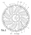
- FIGS Grinding tools (1) shown as Cut-off tools are designed.
- the Cut-off tool can be used as a cut-off wheel (17), especially diamond cutting disc, drill bit (18) or are designed as a flexible saw cable (19).
- the grinding tools (1) each have a supporting body (4) in a suitable different configuration and at least one abrasive coating (5) at a suitable point on the Carrying body (4).
- the grinding surface (5) is located preferably on the outer circumference or overlapping on adjacent edge area (especially in the Cut-off tool) or on the front (e.g. Cup) of the supporting body (4).
- the abrasive coating (5) can consist of one or more grinding elements (12), which are designed as separate parts and with the Support body (4) in any suitable manner, e.g. by Welding, soldering, sintering or the like connected are. Alternatively, the abrasive coating (5) can be made in one piece with be connected to the supporting body (4).
- the grinding tools (1) are bound Grinding tools designed which have a grinding surface (5) in matrix form with a binder (15) and therein embedded grinding wheels (13) and Have abrasive particles (25). They are also hard and low-hard abrasives (10.14) available. The thickness of the Grinding surface (5) is considerably larger than that Diameter of the various grinding wheels contained (13) and abrasives (10.14).
- the abrasive coating (5) has one preferably metallic binder (15) and more than Hollow grain balls (13) trained abrasive, wherein he also one or more types of hard abrasives (10) as abrasive particles (25) and one or more types contains less hard abrasive (14).
- the less hard abrasives (14) are on the outer Surface (24) of the hollow grain spheres (13) arranged.
- the Binders (15) are thus the hard abrasive particles (25) and the hollow grain spheres (13) side by side and preferably evenly distributed as in a matrix embedded.
- the hard and less hard abrasives (10, 14) can be used here from a single uniform material or from Mixtures of different materials exist.
- Another modification is possible in the binder (15) in addition to the hard abrasive particles (10,25) additionally embed less hard abrasives (14).
- the binder (15) can be made of suitable powder Metals and other additives exist. You can e.g. Be iron, tungsten and / or bronze, these being Materials in pure form or in mixed form can.
- the abrasive coating (5) is made of powder or Starting materials present in particle form suitably, e.g. produced by sintering.
- the hard abrasives (10) have a suitable one Particle shape and preferably consist of diamond or made of cubic boron nitride.
- the less hard abrasives (14) consist, for example, of corundum or Silicon carbide. In particular, you can choose whole or partly consist of ceramic corundum.
- the less hard abrasives (14) preferably have a hardness of approx. 16 - 27 GPa (HV1).
- the hard ones Abrasives (10) have e.g. a hardness of approx. 45 GPa (HV1) for cubic boron nitride or a hardness of approx. 70 GPa (HV1) for diamond.
- a preferred combination of hard and less hard Abrasives (10.14) are present when the Difference in hardness between them at least 15 GPa (HV1) is.
- the diameter of the hollow grain spheres (13) including the included in it hard abrasive (14) is preferably 1 to 10 times the average Diameter of the or one of the hard Abrasive particles (10.25). Hollow beads (13) preferably have a diameter of 1 mm or larger.
- the hard abrasive particles (10, 25) have one Diameters from approx. 0.2 mm to 0.8 mm. In Figure 8, the Ratios shown for clarity.
- the diameter of the on the hollow grain sphere (13) arranged less hard abrasive (14) preferably a smaller diameter than the hard ones Abrasives (10), preferably on the order of a third.
- FIG. 8 shows e.g. in the lower right half of the picture schematically one Hollow grain ball (13) in 2-component design, while in a hollow grain sphere (13) in the upper left half of the picture 3-component version is shown.
- the jacket (24) the hollow grain ball (13) from a ceramic or organic material, where, because of the higher thermal and mechanical resilience ceramic Material has advantages.
- the grainy, less hard Abrasives (14), e.g. Korrund is in this Embodiment directly in the jacket (24) or that Surface material of the hollow hollow sphere (13) integrated., a so-called two-component hollow spherical grain is formed.
- this is granular low-hard abrasives (14) by means of an additional, preferably ceramic binder (16) with the outer Surface (24) of the hollow grain ball (13) connected.
- an additional, preferably ceramic binder (16) with the outer Surface (24) of the hollow grain ball (13) connected it is recommended to the body of the Hollow grain ball (13) also made of a ceramic Train material.
- Figure 1 shows a cut-off tool (1) in the form of a Cut-off wheel (17), in particular one Diamond cutting wheel. It has a supporting body (4) in the form of a flat and essentially circular master blade made of steel or another Material that has a central bore (2) for the Axis of rotation (3) and a rotary drive connection and preferably a variety of small hole-shaped ones Has openings (7) in spiral lines (9) are arranged.
- the design can be done in the EP-A-1 099 524 correspond to the design shown.
- the grinding surface (5) consists of several curved ones block-like or segment-shaped grinding elements (12), which as a cutting ring evenly around the circumference of the Are distributed and with the The outer edge of the base sheet by laser welding or on other suitable type are connected.
- Figure 2 shows for this purpose the cutting wheel (17) in the broken Cross section with the weld seam (6) between the outer edge of the master blade and the abutting grinding element (12).
- Figure 2 shows this arrangement schematically dashed lines.
- FIGs 4 and 5 is a grinding tool (1) in the form of a flexible saw cable (19) shown.
- the Carrying body (4) is here of a wire core (20) formed, consistently or in places by one Coil spring (21) is enclosed in places the abrasive coating (5) forming in the longitudinal direction distanced grinding elements (12) is applied.
- the Grinding elements (12) form the so-called grinding beads or beads of the saw cable (19).
- the soul (20) who Spring (21) and also partial areas of the abrasive coating (5) are enclosed by an elastic covering (20) which consists of a suitable plastic that is attached to the the aforementioned parts are cast or molded.
- the Saw cable (19) can be trained accordingly of WO 98/35778.
- FIG. 6 shows a variant of the grinding tool (1) in Shown a so-called drill bit (18).
- the support body (4) here has an essentially cylindrical one tubular and pot-like shape, on the free end face Edge of the abrasive coating (5) in the form of several evenly distributed in a circle and circumferentially spaced grinding elements (12) is arranged.
- the Grinding elements (5) can be placed one below the other in the foot area connected to form a toothed slip ring, what is shown in the upper half of Figure 6.
- the grinding elements (5) individually arranged and directly connected to the support body (4) be what is indicated in the lower half of Figure 6 is.
- the support body (4) can be made of metal, plastic or a other suitable material, the Grinding elements (12) in a suitable manner permanently or possibly interchangeably connected to the support body (4).
- the grinding elements (12) a curved shape and are circumferential aligned.
- the grinding elements (12) have an essentially radial orientation.
- FIG. 7 shows a further variant of a grinding tool (1), which here as a curved or flat cup (23) is formed.
- the supporting body (4) has e.g. a pot-like shape with a central bore (2).
- the Abrasive coating (5) here again consists of several block-shaped grinding elements (12) on the front of the cup wheel (23), i.e. at the bottom of a Outer ring and possibly also on connecting webs permanently or are arranged interchangeably.
- the grinding elements (12) are oriented essentially in the circumferential direction and can be slightly slanted or have a curved shape in the circumferential direction.
- the Cutting wheel (17) in the manner of a whole sintered disc be formed, in which the Support body or disc body and the abrasive coating are integrally connected.
- the sintered one Disk body can be concentric in several divide annular sections that are homogeneous and are integrally connected by sintering. In these ring sections are different material Compositions of the sintered material present.
- Modifications of the exemplary embodiments shown are in possible in different ways. Basically, it can Grinding tool (1) with its supporting body (4) and its Abrasive coating (5) have any suitable shape and adapt to different purposes to let.
- the grinding tool (1) can not only be used for cutting or slitting hard materials, but also for Surface removal can be used.
- the specified Material components can be interchanged or can be combined with one another as required.
Landscapes
- Engineering & Computer Science (AREA)
- Chemical & Material Sciences (AREA)
- Mechanical Engineering (AREA)
- Ceramic Engineering (AREA)
- Inorganic Chemistry (AREA)
- Polishing Bodies And Polishing Tools (AREA)
- Lubricants (AREA)
Abstract
Description
Das erfindungsgemäße Schleifwerkzeug hat den Vorteil, dass es eine wesentlich bessere Schneidleistung und eine längere Standzeit bietet. Insbesondere kann hierbei auch die Schnittgeschwindigkeit gegenüber vorbekannten Schleifwerkzeugen erhöht und über längere Zeit aufrecht erhalten werden.
- Figur 1:
- ein Schleifwerkzeug in Form einer Trennschleifscheibe mit einem Tragkörper und einem Schleifbelag in Draufsicht,
- Figur 2:
- einen Querschnitt durch die Trennschleifscheibe gemäß Schnittlinie II - II von Figur 1,
- Figur 3:
- eine andere Trennschleifscheibe in Draufsicht,
- Figur 4:
- ein Schleifwerkzeug in Form eines Sägeseils mit Schleifperlen,
- Figur 5:
- eine geschnittene und vergrößerte Darstellung einer Schleifperle,
- Figur 6:
- ein Schleifwerkzeug in Form einer Bohrkrone,
- Figur 7:
- ein Schleifwerkzeug in Form eines Schleiftopfes und
- Figur 8:
- einen vergrößerten schematischen Ausschnitt des Schleifbelags mit Kornhohlkugeln und Diamantpartikeln in einem Bindemittel.
- 1
- Schleifwerkzeug
- 2
- Zentralbohrung
- 3
- Drehachse
- 4
- Tragkörper, Scheibenkörper
- 5
- Schleifbelag
- 6
- Verbindungsnaht, Schweißnaht
- 7
- Durchbrechung
- 8
- zusätzlicher Schneidbelag, Diamantbelag
- 9
- Spirallinie
- 10
- hartes Schleifmittel, Diamant, kubisches Bornitrid
- 11
- Hinterschnitt
- 12
- Schleifelement
- 13
- Schleifkörper, Kornhohlkugel
- 14
- minderhartes Schleifmittel, Korrund, Siliziumkarbid
- 15
- Bindemittel, Matrix für Schleifbelag
- 16
- Bindemittel für Kornhohlkugel
- 17
- Trennschleifscheibe, Diamant-Trennschleifscheibe
- 18
- Bohrkrone
- 19
- Sägeseil
- 20
- Seele
- 21
- Feder
- 22
- elastische Umhüllung
- 23
- Schleiftopf
- 24
- Mantel, äußere Oberfläche der Kornhohlkugel
- 25
- Schleifpartikel
Claims (16)
- Gebundenes Schleifwerkzeug, vorzugsweise Trennschleifwerkzeug, enthaltend einen Schleifbelag (5) mit einem vorzugsweise metallischen Bindemittel (15) und Schleifmaterialien, dadurch gekennzeichnet, dassder Schleifbelag (5) eine Mischung von Schleifkörpern (13) und Schleifpartikeln (25) enthält,die Schleifkörper (13) als Kornhohlkugeln ausgebildet sind,der Schleifbelag (5) ein oder mehrere Arten harter Schleifmittel (10) sowie ein oder mehrere Arten minderharter Schleifmittel (14) enthält,wobei die minderharten Schleifmittel (14) an der äußeren Oberfläche der Kornhohlkugeln (13) angeordnet sind unddie harten Schleifmittel (10) die Schleifpartikel (25) bilden.
- Schleifwerkzeug nach Anspruch 1, dadurch gekennzeichnet, dass das Schleifwerkzeug (1) einen Tragkörper (4) mit einem umfangseitig oder stirnseitig angeordneten Schleifbelag (5) aufweist.
- Schleifwerkzeug nach Anspruch 1 oder 2, dadurch gekennzeichnet, dass als harte Schleifmittel (10) Diamant und/oder kubisches Bornitrid enthalten sind.
- Schleifwerkzeug nach einem der vorhergehenden Ansprüche, dadurch gekennzeichnet, dass als minderharte Schleifmittel Korund und/oder Siliziumkarbid enthalten sind.
- Schleifwerkzeug nach Anspruch 4, dadurch gekennzeichnet, dass die minderharten Schleifmittel (14) ganz oder teilweise aus keramischem Korund bestehen.
- Schleifwerkzeug nach einem der vorhergehenden Ansprüche, dadurch gekennzeichnet, dass der Härteunterschied zwischen dem harten (10) und dem minderharten Schleifmittel (14) mindestens 15 Gpa (HV 1) beträgt.
- Schleifwerkzeug nach einem der vorhergehenden Ansprüche, dadurch gekennzeichnet, dass die Kornhohlkugeln (13) aus einem keramischen Material bestehen, in das minderharte körnige Schleifmittel (14) ohne ein weiteres Bindemittel unmittelbar in die äußere Oberfläche (24) der Kornhohlkugeln (13) eingebunden sind.
- Schleifwerkzeug nach einem der vorhergehenden Ansprüche, dadurch gekennzeichnet, dass der Körper der Kornhohlkugel (13) aus einem keramischen Material besteht und das minderharte Schleifmittel (14) mittels eines keramischen Bindemittels (16) mit der äußeren Oberfläche (24) der Kornhohlkugel (13) verbunden ist.
- Schleifwerkzeug nach einem der vorhergehenden Ansprüche, dadurch gekennzeichnet, dass der Durchmesser der Kornhohlkugel (13) einschließlich des darin eingebundenen minderharten Schleifmittels (14) das 1 bis 10-fache des mittleren Durchmessers des oder eines der harten Schleifmittel (10) beträgt.
- Schleifwerkzeug nach einem der vorhergehenden Ansprüche, dadurch gekennzeichnet, dass die minderharten körnigen Schleifmittel (14) einen kleineren Durchmesser als die harten Schleifmittelpartikel (10,25) aufweist.
- Schleifwerkzeug nach einem der vorhergehenden Ansprüche, dadurch gekennzeichnet, dass der Schleifbelag (5) von ein oder mehreren Schleifelementen (12) gebildet ist, die mit dem Tragkörper (4) verbunden sind.
- Schleifwerkzeug nach Anspruch 11, dadurch gekennzeichnet, dass der Tragkörper (4) aus einem anderen Material als der Schleifbelag (5) besteht.
- Schleifwerkzeug nach einem der vorhergehenden Ansprüche 1 bis 10, dadurch gekennzeichnet, dass der Schleifbelag (5) Bestandteil eines in Gänze oder zumindest zum Teil gesinterten Tragkörpers (4) ist.
- Schleifwerkzeug nach einem der vorhergehenden Ansprüche, dadurch gekennzeichnet, dass der Tragkörper (4) außer dem Schleifbelag (5) mindestens einen zusätzlichen Schneidbelag (8) aufweist.
- Schleifwerkzeug nach einem der vorhergehenden Ansprüche, dadurch gekennzeichnet, dass das Trennschleifwerkzeug (1) als Trennschleifscheibe (17), als Bohrkrone (18) oder als flexibles Sägeseil (19) ausgebildet ist.
- Schleifwerkzeug nach einem der vorhergehenden Ansprüche, dadurch gekennzeichnet, dass das Schleifwerkzeug (1) als Schleiftopf (23) ausgebildet ist.
Applications Claiming Priority (2)
| Application Number | Priority Date | Filing Date | Title |
|---|---|---|---|
| DE20203238U DE20203238U1 (de) | 2002-03-01 | 2002-03-01 | Schleifwerkzeug, insbesondere Trennschleifwerkzeug |
| DE20203238U | 2002-03-01 |
Publications (2)
| Publication Number | Publication Date |
|---|---|
| EP1340593A1 true EP1340593A1 (de) | 2003-09-03 |
| EP1340593B1 EP1340593B1 (de) | 2005-11-16 |
Family
ID=27588683
Family Applications (1)
| Application Number | Title | Priority Date | Filing Date |
|---|---|---|---|
| EP03004472A Expired - Lifetime EP1340593B1 (de) | 2002-03-01 | 2003-02-27 | Schleifwerkzeug, insbesondere Trennschleifwerkzeug |
Country Status (5)
| Country | Link |
|---|---|
| EP (1) | EP1340593B1 (de) |
| AT (1) | ATE309885T1 (de) |
| DE (2) | DE20203238U1 (de) |
| DK (1) | DK1340593T3 (de) |
| ES (1) | ES2253595T3 (de) |
Cited By (2)
| Publication number | Priority date | Publication date | Assignee | Title |
|---|---|---|---|---|
| EP1442861A3 (de) * | 2003-02-03 | 2004-08-18 | HILTI Aktiengesellschaft | Schneidblatt mit Geräuschdämpfungsbohrung |
| EP3036064A4 (de) * | 2013-08-23 | 2017-05-24 | Saint-Gobain K.K. | Schleifartikel |
Families Citing this family (1)
| Publication number | Priority date | Publication date | Assignee | Title |
|---|---|---|---|---|
| KR100778280B1 (ko) * | 2007-02-02 | 2007-11-22 | 조성행 | 절삭팁 |
Citations (4)
| Publication number | Priority date | Publication date | Assignee | Title |
|---|---|---|---|---|
| GB2102445A (en) * | 1981-06-20 | 1983-02-02 | Abrafract Manufacturing Limite | Abrasive material and method of making it |
| SU1726220A1 (ru) * | 1989-07-14 | 1992-04-15 | Научно-Исследовательский Институт Конструкционных Материалов И Технологических Процессов При Мгту@ Им.Н.Э.Баумана | Абразивный инструмент дл доводки |
| EP1099524A2 (de) * | 1999-06-15 | 2001-05-16 | DIEWE-Diamantwerkzeuge GmbH | Trennscheibe mit in einer Spiralform angeordneten Durchbrechungen |
| WO2002016082A1 (de) * | 2000-08-23 | 2002-02-28 | Hermes Schleifmittel Gmbh & Co. | Honwerkzeug |
Family Cites Families (3)
| Publication number | Priority date | Publication date | Assignee | Title |
|---|---|---|---|---|
| ATA853572A (de) * | 1972-10-05 | 1975-08-15 | Tschirf Ludwig Dipl Ing Dr Tec | Schleifkorngemisch und schleifkorn |
| DE2350139C3 (de) * | 1973-10-05 | 1984-05-10 | Norddeutsche Schleifmittel-Industrie Christiansen & Co (GmbH & Co), 2000 Hamburg | Hohlkörperförmiger Schleifkörper |
| DE2951067A1 (de) * | 1979-12-19 | 1981-08-20 | Norddeutsche Schleifmittel-Industrie Christiansen & Co, GmbH & Co, 2000 Hamburg | Schleifwerkzeug, in welchem keramikgebundene schleifkornkonglomerate durch ein organisches bindemittel miteinander bzw. mit einer unterlage verbunden sind |
-
2002
- 2002-03-01 DE DE20203238U patent/DE20203238U1/de not_active Expired - Lifetime
-
2003
- 2003-02-27 ES ES03004472T patent/ES2253595T3/es not_active Expired - Lifetime
- 2003-02-27 AT AT03004472T patent/ATE309885T1/de active
- 2003-02-27 DK DK03004472T patent/DK1340593T3/da active
- 2003-02-27 DE DE50301640T patent/DE50301640D1/de not_active Expired - Lifetime
- 2003-02-27 EP EP03004472A patent/EP1340593B1/de not_active Expired - Lifetime
Patent Citations (4)
| Publication number | Priority date | Publication date | Assignee | Title |
|---|---|---|---|---|
| GB2102445A (en) * | 1981-06-20 | 1983-02-02 | Abrafract Manufacturing Limite | Abrasive material and method of making it |
| SU1726220A1 (ru) * | 1989-07-14 | 1992-04-15 | Научно-Исследовательский Институт Конструкционных Материалов И Технологических Процессов При Мгту@ Им.Н.Э.Баумана | Абразивный инструмент дл доводки |
| EP1099524A2 (de) * | 1999-06-15 | 2001-05-16 | DIEWE-Diamantwerkzeuge GmbH | Trennscheibe mit in einer Spiralform angeordneten Durchbrechungen |
| WO2002016082A1 (de) * | 2000-08-23 | 2002-02-28 | Hermes Schleifmittel Gmbh & Co. | Honwerkzeug |
Non-Patent Citations (1)
| Title |
|---|
| DATABASE WPI Section Ch Week 199311, Derwent World Patents Index; Class L02, AN 1993-092242, XP002244016 * |
Cited By (2)
| Publication number | Priority date | Publication date | Assignee | Title |
|---|---|---|---|---|
| EP1442861A3 (de) * | 2003-02-03 | 2004-08-18 | HILTI Aktiengesellschaft | Schneidblatt mit Geräuschdämpfungsbohrung |
| EP3036064A4 (de) * | 2013-08-23 | 2017-05-24 | Saint-Gobain K.K. | Schleifartikel |
Also Published As
| Publication number | Publication date |
|---|---|
| DK1340593T3 (da) | 2006-03-27 |
| EP1340593B1 (de) | 2005-11-16 |
| DE50301640D1 (de) | 2005-12-22 |
| DE20203238U1 (de) | 2003-07-10 |
| ES2253595T3 (es) | 2006-06-01 |
| ATE309885T1 (de) | 2005-12-15 |
Similar Documents
| Publication | Publication Date | Title |
|---|---|---|
| DE2643617A1 (de) | Saegedraht | |
| DE69812358T2 (de) | Hochleistungsschleif-schneidfläche | |
| DE69922230T2 (de) | Diamantiertes Blatt mit felgenförmigen Schneidrand zur Verwendung in Schleif- und Schneidvorrichtungen | |
| EP3898037B1 (de) | Verfahren zur herstellung eines bearbeitungssegmentes für die trockenbearbeitung von betonwerkstoffen | |
| EP3670050A1 (de) | Bearbeitungssegment für ein bearbeitungswerkzeug | |
| DE1502642A1 (de) | Diamantformwerkzeug | |
| EP3670037A1 (de) | Verfahren zur herstellung eines bearbeitungssegmentes für die trockenbearbeitung von betonwerkstoffen | |
| DE10130477A1 (de) | Schleifscheibe mit Segmenten zum Verhindern einseitiger Abnutzung | |
| DE1951480A1 (de) | Werkzeug zum Saegen,Schneiden,Trennen u.dgl.,Arbeitselement zur Bildung eines solchen Werkzeuges sowie Herstellungsverfahren dazu | |
| DE2916347B2 (de) | Lagerstuhl für Direktantriebe von Tiefbohrmeißeln o.dgl. in einem Bohrloch arbeitenden Werkzeugen oder Geräten | |
| AT504926B1 (de) | Abrichtwerkzeug | |
| DE8420322U1 (de) | Schleiftrennscheibe | |
| EP0896867A2 (de) | Sägeblatt mit thermisch entkoppelnder Verbindung von Schneidesegmenten auf Stammblatt | |
| EP1340593B1 (de) | Schleifwerkzeug, insbesondere Trennschleifwerkzeug | |
| EP0540566B1 (de) | Schneidwerkzeug | |
| DE6925061U (de) | Schleifwerkzeug | |
| CH701596A1 (de) | Abrichtwerkzeug. | |
| DE4300417C2 (de) | Rotierendes oder schwingendes Schleifwerkzeug mit einem Grundkörper, der aus räumlich angeordneten und miteinander verbundenen Stegen aufgebaut ist, sowie Herstellungsverfahren für ein derartiges Schleifwerkzeug | |
| AT400543B (de) | Metallgebundenes abrasivwerkzeug mit füllstoff | |
| EP0489092B1 (de) | Abrichten von schleifscheiben | |
| EP3928895A1 (de) | Verfahren zur herstellung eines grünlings und verfahren zur weiterverarbeitung des grünlings in ein bearbeitungssegment | |
| EP3928905A1 (de) | Verfahren zur herstellung eines grünlings und verfahren zur weiterverarbeitung des grünlings in ein bearbeitungssegment | |
| DE102009030484A1 (de) | Segmenttrennschleifscheibe | |
| DE102019117799B4 (de) | Zerspanungswerkzeug mit asymmetrischen Zähnen mit Schneidpartikeln | |
| EP3437761A1 (de) | Verfahren zur herstellung eines bearbeitungssegmentes für ein abrasives bearbeitungswerkzeug |
Legal Events
| Date | Code | Title | Description |
|---|---|---|---|
| PUAI | Public reference made under article 153(3) epc to a published international application that has entered the european phase |
Free format text: ORIGINAL CODE: 0009012 |
|
| AK | Designated contracting states |
Kind code of ref document: A1 Designated state(s): AT BE BG CH CY CZ DE DK EE ES FI FR GB GR HU IE IT LI LU MC NL PT SE SI SK TR |
|
| AX | Request for extension of the european patent |
Extension state: AL LT LV MK RO |
|
| 17P | Request for examination filed |
Effective date: 20031126 |
|
| AKX | Designation fees paid |
Designated state(s): AT BE BG CH CY CZ DE DK EE ES FI FR GB GR HU IE IT LI LU MC NL PT SE SI SK TR |
|
| 17Q | First examination report despatched |
Effective date: 20041210 |
|
| GRAP | Despatch of communication of intention to grant a patent |
Free format text: ORIGINAL CODE: EPIDOSNIGR1 |
|
| GRAS | Grant fee paid |
Free format text: ORIGINAL CODE: EPIDOSNIGR3 |
|
| GRAA | (expected) grant |
Free format text: ORIGINAL CODE: 0009210 |
|
| AK | Designated contracting states |
Kind code of ref document: B1 Designated state(s): AT BE BG CH CY CZ DE DK EE ES FI FR GB GR HU IE IT LI LU MC NL PT SE SI SK TR |
|
| PG25 | Lapsed in a contracting state [announced via postgrant information from national office to epo] |
Ref country code: SI Free format text: LAPSE BECAUSE OF FAILURE TO SUBMIT A TRANSLATION OF THE DESCRIPTION OR TO PAY THE FEE WITHIN THE PRESCRIBED TIME-LIMIT Effective date: 20051116 Ref country code: FI Free format text: LAPSE BECAUSE OF FAILURE TO SUBMIT A TRANSLATION OF THE DESCRIPTION OR TO PAY THE FEE WITHIN THE PRESCRIBED TIME-LIMIT Effective date: 20051116 Ref country code: CZ Free format text: LAPSE BECAUSE OF FAILURE TO SUBMIT A TRANSLATION OF THE DESCRIPTION OR TO PAY THE FEE WITHIN THE PRESCRIBED TIME-LIMIT Effective date: 20051116 Ref country code: SK Free format text: LAPSE BECAUSE OF FAILURE TO SUBMIT A TRANSLATION OF THE DESCRIPTION OR TO PAY THE FEE WITHIN THE PRESCRIBED TIME-LIMIT Effective date: 20051116 Ref country code: IE Free format text: LAPSE BECAUSE OF FAILURE TO SUBMIT A TRANSLATION OF THE DESCRIPTION OR TO PAY THE FEE WITHIN THE PRESCRIBED TIME-LIMIT Effective date: 20051116 |
|
| REG | Reference to a national code |
Ref country code: GB Ref legal event code: FG4D Free format text: NOT ENGLISH |
|
| REG | Reference to a national code |
Ref country code: CH Ref legal event code: EP |
|
| REG | Reference to a national code |
Ref country code: IE Ref legal event code: FG4D Free format text: LANGUAGE OF EP DOCUMENT: GERMAN |
|
| REF | Corresponds to: |
Ref document number: 50301640 Country of ref document: DE Date of ref document: 20051222 Kind code of ref document: P |
|
| REG | Reference to a national code |
Ref country code: CH Ref legal event code: NV Representative=s name: E. BLUM & CO. PATENTANWAELTE |
|
| PG25 | Lapsed in a contracting state [announced via postgrant information from national office to epo] |
Ref country code: BG Free format text: LAPSE BECAUSE OF FAILURE TO SUBMIT A TRANSLATION OF THE DESCRIPTION OR TO PAY THE FEE WITHIN THE PRESCRIBED TIME-LIMIT Effective date: 20060216 Ref country code: GR Free format text: LAPSE BECAUSE OF FAILURE TO SUBMIT A TRANSLATION OF THE DESCRIPTION OR TO PAY THE FEE WITHIN THE PRESCRIBED TIME-LIMIT Effective date: 20060216 Ref country code: SE Free format text: LAPSE BECAUSE OF FAILURE TO SUBMIT A TRANSLATION OF THE DESCRIPTION OR TO PAY THE FEE WITHIN THE PRESCRIBED TIME-LIMIT Effective date: 20060216 |
|
| PG25 | Lapsed in a contracting state [announced via postgrant information from national office to epo] |
Ref country code: MC Free format text: LAPSE BECAUSE OF NON-PAYMENT OF DUE FEES Effective date: 20060228 Ref country code: LU Free format text: LAPSE BECAUSE OF NON-PAYMENT OF DUE FEES Effective date: 20060228 |
|
| GBT | Gb: translation of ep patent filed (gb section 77(6)(a)/1977) |
Effective date: 20060301 |
|
| REG | Reference to a national code |
Ref country code: DK Ref legal event code: T3 |
|
| PG25 | Lapsed in a contracting state [announced via postgrant information from national office to epo] |
Ref country code: HU Free format text: LAPSE BECAUSE OF FAILURE TO SUBMIT A TRANSLATION OF THE DESCRIPTION OR TO PAY THE FEE WITHIN THE PRESCRIBED TIME-LIMIT Effective date: 20060517 |
|
| REG | Reference to a national code |
Ref country code: ES Ref legal event code: FG2A Ref document number: 2253595 Country of ref document: ES Kind code of ref document: T3 |
|
| REG | Reference to a national code |
Ref country code: IE Ref legal event code: FD4D |
|
| ET | Fr: translation filed | ||
| PLBE | No opposition filed within time limit |
Free format text: ORIGINAL CODE: 0009261 |
|
| STAA | Information on the status of an ep patent application or granted ep patent |
Free format text: STATUS: NO OPPOSITION FILED WITHIN TIME LIMIT |
|
| 26N | No opposition filed |
Effective date: 20060817 |
|
| REG | Reference to a national code |
Ref country code: CH Ref legal event code: PFA Owner name: DIEWE-DIAMANTWERKZEUGE GMBH Free format text: DIEWE-DIAMANTWERKZEUGE GMBH#HAUPTSTRASSE 19#86510 ASBACH /RIED (DE) -TRANSFER TO- DIEWE-DIAMANTWERKZEUGE GMBH#HAUPTSTRASSE 19#86510 ASBACH /RIED (DE) |
|
| PG25 | Lapsed in a contracting state [announced via postgrant information from national office to epo] |
Ref country code: EE Free format text: LAPSE BECAUSE OF FAILURE TO SUBMIT A TRANSLATION OF THE DESCRIPTION OR TO PAY THE FEE WITHIN THE PRESCRIBED TIME-LIMIT Effective date: 20051116 |
|
| PG25 | Lapsed in a contracting state [announced via postgrant information from national office to epo] |
Ref country code: TR Free format text: LAPSE BECAUSE OF FAILURE TO SUBMIT A TRANSLATION OF THE DESCRIPTION OR TO PAY THE FEE WITHIN THE PRESCRIBED TIME-LIMIT Effective date: 20051116 |
|
| PG25 | Lapsed in a contracting state [announced via postgrant information from national office to epo] |
Ref country code: CY Free format text: LAPSE BECAUSE OF FAILURE TO SUBMIT A TRANSLATION OF THE DESCRIPTION OR TO PAY THE FEE WITHIN THE PRESCRIBED TIME-LIMIT Effective date: 20051116 |
|
| PGFP | Annual fee paid to national office [announced via postgrant information from national office to epo] |
Ref country code: FR Payment date: 20120228 Year of fee payment: 10 |
|
| PGFP | Annual fee paid to national office [announced via postgrant information from national office to epo] |
Ref country code: PT Payment date: 20120216 Year of fee payment: 10 |
|
| PGFP | Annual fee paid to national office [announced via postgrant information from national office to epo] |
Ref country code: BE Payment date: 20120221 Year of fee payment: 10 Ref country code: GB Payment date: 20120222 Year of fee payment: 10 Ref country code: IT Payment date: 20120224 Year of fee payment: 10 Ref country code: DK Payment date: 20120216 Year of fee payment: 10 |
|
| PGFP | Annual fee paid to national office [announced via postgrant information from national office to epo] |
Ref country code: NL Payment date: 20120224 Year of fee payment: 10 |
|
| PGFP | Annual fee paid to national office [announced via postgrant information from national office to epo] |
Ref country code: CH Payment date: 20130220 Year of fee payment: 11 |
|
| PGFP | Annual fee paid to national office [announced via postgrant information from national office to epo] |
Ref country code: ES Payment date: 20120221 Year of fee payment: 10 Ref country code: AT Payment date: 20130222 Year of fee payment: 11 |
|
| BERE | Be: lapsed |
Owner name: *DIEWE-DIAMANTWERKZEUGE G.M.B.H. Effective date: 20130228 |
|
| REG | Reference to a national code |
Ref country code: PT Ref legal event code: MM4A Free format text: LAPSE DUE TO NON-PAYMENT OF FEES Effective date: 20130827 |
|
| REG | Reference to a national code |
Ref country code: NL Ref legal event code: V1 Effective date: 20130901 |
|
| REG | Reference to a national code |
Ref country code: DK Ref legal event code: EBP |
|
| GBPC | Gb: european patent ceased through non-payment of renewal fee |
Effective date: 20130227 |
|
| PG25 | Lapsed in a contracting state [announced via postgrant information from national office to epo] |
Ref country code: NL Free format text: LAPSE BECAUSE OF NON-PAYMENT OF DUE FEES Effective date: 20130901 Ref country code: PT Free format text: LAPSE BECAUSE OF NON-PAYMENT OF DUE FEES Effective date: 20130827 |
|
| REG | Reference to a national code |
Ref country code: FR Ref legal event code: ST Effective date: 20131031 |
|
| PG25 | Lapsed in a contracting state [announced via postgrant information from national office to epo] |
Ref country code: GB Free format text: LAPSE BECAUSE OF NON-PAYMENT OF DUE FEES Effective date: 20130227 Ref country code: BE Free format text: LAPSE BECAUSE OF NON-PAYMENT OF DUE FEES Effective date: 20130228 Ref country code: DK Free format text: LAPSE BECAUSE OF NON-PAYMENT OF DUE FEES Effective date: 20130228 Ref country code: FR Free format text: LAPSE BECAUSE OF NON-PAYMENT OF DUE FEES Effective date: 20130228 |
|
| REG | Reference to a national code |
Ref country code: ES Ref legal event code: FD2A Effective date: 20140408 |
|
| PG25 | Lapsed in a contracting state [announced via postgrant information from national office to epo] |
Ref country code: ES Free format text: LAPSE BECAUSE OF NON-PAYMENT OF DUE FEES Effective date: 20130228 |
|
| REG | Reference to a national code |
Ref country code: CH Ref legal event code: PL |
|
| REG | Reference to a national code |
Ref country code: AT Ref legal event code: MM01 Ref document number: 309885 Country of ref document: AT Kind code of ref document: T Effective date: 20140227 |
|
| PG25 | Lapsed in a contracting state [announced via postgrant information from national office to epo] |
Ref country code: LI Free format text: LAPSE BECAUSE OF NON-PAYMENT OF DUE FEES Effective date: 20140228 Ref country code: CH Free format text: LAPSE BECAUSE OF NON-PAYMENT OF DUE FEES Effective date: 20140228 |
|
| PG25 | Lapsed in a contracting state [announced via postgrant information from national office to epo] |
Ref country code: AT Free format text: LAPSE BECAUSE OF NON-PAYMENT OF DUE FEES Effective date: 20140227 |
|
| PG25 | Lapsed in a contracting state [announced via postgrant information from national office to epo] |
Ref country code: IT Free format text: LAPSE BECAUSE OF NON-PAYMENT OF DUE FEES Effective date: 20140227 |
|
| PGFP | Annual fee paid to national office [announced via postgrant information from national office to epo] |
Ref country code: DE Payment date: 20220216 Year of fee payment: 20 |
|
| REG | Reference to a national code |
Ref country code: DE Ref legal event code: R071 Ref document number: 50301640 Country of ref document: DE |