EP1340916A2 - Pompe à vide du type à vis - Google Patents
Pompe à vide du type à vis Download PDFInfo
- Publication number
- EP1340916A2 EP1340916A2 EP03004552A EP03004552A EP1340916A2 EP 1340916 A2 EP1340916 A2 EP 1340916A2 EP 03004552 A EP03004552 A EP 03004552A EP 03004552 A EP03004552 A EP 03004552A EP 1340916 A2 EP1340916 A2 EP 1340916A2
- Authority
- EP
- European Patent Office
- Prior art keywords
- vacuum pump
- screw rotors
- exhaust port
- suction port
- pump according
- Prior art date
- Legal status (The legal status is an assumption and is not a legal conclusion. Google has not performed a legal analysis and makes no representation as to the accuracy of the status listed.)
- Withdrawn
Links
Images


Classifications
-
- F—MECHANICAL ENGINEERING; LIGHTING; HEATING; WEAPONS; BLASTING
- F04—POSITIVE - DISPLACEMENT MACHINES FOR LIQUIDS; PUMPS FOR LIQUIDS OR ELASTIC FLUIDS
- F04C—ROTARY-PISTON, OR OSCILLATING-PISTON, POSITIVE-DISPLACEMENT MACHINES FOR LIQUIDS; ROTARY-PISTON, OR OSCILLATING-PISTON, POSITIVE-DISPLACEMENT PUMPS
- F04C29/00—Component parts, details or accessories of pumps or pumping installations, not provided for in groups F04C18/00 - F04C28/00
- F04C29/12—Arrangements for admission or discharge of the working fluid, e.g. constructional features of the inlet or outlet
-
- F—MECHANICAL ENGINEERING; LIGHTING; HEATING; WEAPONS; BLASTING
- F04—POSITIVE - DISPLACEMENT MACHINES FOR LIQUIDS; PUMPS FOR LIQUIDS OR ELASTIC FLUIDS
- F04C—ROTARY-PISTON, OR OSCILLATING-PISTON, POSITIVE-DISPLACEMENT MACHINES FOR LIQUIDS; ROTARY-PISTON, OR OSCILLATING-PISTON, POSITIVE-DISPLACEMENT PUMPS
- F04C18/00—Rotary-piston pumps specially adapted for elastic fluids
- F04C18/08—Rotary-piston pumps specially adapted for elastic fluids of intermeshing-engagement type, i.e. with engagement of co-operating members similar to that of toothed gearing
- F04C18/12—Rotary-piston pumps specially adapted for elastic fluids of intermeshing-engagement type, i.e. with engagement of co-operating members similar to that of toothed gearing of other than internal-axis type
- F04C18/14—Rotary-piston pumps specially adapted for elastic fluids of intermeshing-engagement type, i.e. with engagement of co-operating members similar to that of toothed gearing of other than internal-axis type with toothed rotary pistons
- F04C18/16—Rotary-piston pumps specially adapted for elastic fluids of intermeshing-engagement type, i.e. with engagement of co-operating members similar to that of toothed gearing of other than internal-axis type with toothed rotary pistons with helical teeth, e.g. chevron-shaped, screw type
-
- F—MECHANICAL ENGINEERING; LIGHTING; HEATING; WEAPONS; BLASTING
- F04—POSITIVE - DISPLACEMENT MACHINES FOR LIQUIDS; PUMPS FOR LIQUIDS OR ELASTIC FLUIDS
- F04C—ROTARY-PISTON, OR OSCILLATING-PISTON, POSITIVE-DISPLACEMENT MACHINES FOR LIQUIDS; ROTARY-PISTON, OR OSCILLATING-PISTON, POSITIVE-DISPLACEMENT PUMPS
- F04C2220/00—Application
- F04C2220/10—Vacuum
- F04C2220/12—Dry running
-
- F—MECHANICAL ENGINEERING; LIGHTING; HEATING; WEAPONS; BLASTING
- F04—POSITIVE - DISPLACEMENT MACHINES FOR LIQUIDS; PUMPS FOR LIQUIDS OR ELASTIC FLUIDS
- F04C—ROTARY-PISTON, OR OSCILLATING-PISTON, POSITIVE-DISPLACEMENT MACHINES FOR LIQUIDS; ROTARY-PISTON, OR OSCILLATING-PISTON, POSITIVE-DISPLACEMENT PUMPS
- F04C2250/00—Geometry
- F04C2250/10—Geometry of the inlet or outlet
-
- F—MECHANICAL ENGINEERING; LIGHTING; HEATING; WEAPONS; BLASTING
- F04—POSITIVE - DISPLACEMENT MACHINES FOR LIQUIDS; PUMPS FOR LIQUIDS OR ELASTIC FLUIDS
- F04C—ROTARY-PISTON, OR OSCILLATING-PISTON, POSITIVE-DISPLACEMENT MACHINES FOR LIQUIDS; ROTARY-PISTON, OR OSCILLATING-PISTON, POSITIVE-DISPLACEMENT PUMPS
- F04C29/00—Component parts, details or accessories of pumps or pumping installations, not provided for in groups F04C18/00 - F04C28/00
- F04C29/0092—Removing solid or liquid contaminants from the gas under pumping, e.g. by filtering or deposition; Purging; Scrubbing; Cleaning
Definitions
- the present invention relates to an oil-free screw type vacuum pump, provided with a suction port and a discharge port, for discharging gas.
- the vacuum pump according to the present invention is preferably applicable to discharge such gas that is sucked from a process chamber during surface treatment in a process for manufacturing, for example, semiconductor products, electronic products and so on, and that contains gaseous components which may risk operation of the vacuum pump.
- CVD chemical vapor deposition apparatus
- the chemical vapor deposition apparatus for example, includes a reaction chamber, a heater for heating this reaction chamber, a furnace port flange provided below this reaction chamber, a stock gas supply system connected to the furnace port flange, and an exhaust system connected to an upper part inside the reaction chamber.
- a silica boat carrying thereon a number of objects to be treated is arranged at a predetermined position in the reaction chamber, and the stock gas such as SiH4, SiH2Cl2, NH3, etc. is supplied to the reaction chamber under a reduced pressure and while heating, to form a reaction-formed film such as a poly Si film, a silicone nitride film, etc. on the objects to be treated.
- the gas required for producing the semiconductors has been supplied to a wafer which is arranged inside a vacuum chamber to conduct the treatment of the wafer. All the gas after the treatment in the vacuum chamber has been sucked from the vacuum chamber by means of a vacuum pump, and thereafter, has been exhausted to the atmosphere or to a treatment device through an outlet of the pump.
- CVD chemical vapor deposition apparatus
- etching apparatus the gas required for producing the semiconductors has been supplied to a wafer which is arranged inside a vacuum chamber to conduct the treatment of the wafer. All the gas after the treatment in the vacuum chamber has been sucked from the vacuum chamber by means of a vacuum pump, and thereafter, has been exhausted to the atmosphere or to a treatment device through an outlet of the pump.
- an oil-free dry vacuum pump has been employed so that oil molecules may not leak to a process chamber.
- the vacuum pump for the apparatus for manufacturing the semiconductors besides using singly the dry vacuum pump such as a screw type pump, a turbo molecule pump, etc., there has been employed a multi-step vacuum pump including a plurality of the pumps combined together to increase exhausting efficiency.
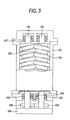
- the screw type dry vacuum pump has two shafts 101, 102 held in parallel in a casing 100. Screw rotors 103, 104, which have screw grooves in mesh with each other, are fixed to the shafts 101, 102.
- One of the shafts i.e.
- the shaft 101 is driven to rotate by means of a motor 105, and the rotation is transmitted to the other shaft 102 by way of a gear 106 which is provided at the end of the shaft 101.
- the casing 100 is provided with a suction port 107 and an exhaust port 108.
- Function of the screw type vacuum pump includes a suction step of sucking the gas from the suction port 107 into the rotors, a transfer step of transferring the gas within the rotors, and a discharge step of discharging the gas from the exhaust port 108.
- Precipitation and formation of the solid matters may be carried out through chemical reactions between gas components to be exhausted by the pump, reactions of the gas components on a surface, and/or catalytic effects. Besides such chemical reactions, formation of the solid matters may occur also with a change of agglomeration state caused by a rise of pressure or cooling.
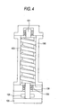
- the exhaust port 108 of the conventional screw type dry vacuum pump has been provided in a bottom part of the housing, as shown in Fig. 4, in order to increase exhausting efficiency. Therefore, because bearings 109 for rotatably fixing the screw rotors have been arranged in the bottom part, a sectional shape of the exhaust port has been restricted in size.
- the suction port 107 has been provided in a ceiling portion of the casing 100 in order to increase a conductance because the vacuum pump, generally arranged vertically, is disposed just below the vacuum chamber.
- the vacuum pump such as the screw type dry vacuum pump which has a function of exhausting by pressurizing the gas
- the pressure of the reaction-forming gas has risen in the pressurizing process just before exhaustion, and solid products have been created because of a change of the coagulation state near the exhaust port.
- the exhaust port of the screw type dry vacuum pump has been generally provided in a bottom face at an exhausting side of the housing which contains the screws, and the gas has been exhausted from the bottom face.
- it has been impossible to make a sectional area of the exhaust port large, because there has been provided a structure including the bearings for fixing the screw rotors and seal mechanisms for preventing a leak of lubricating oil to the exhaust chamber. For this reason, there has been such a problem that when the above described solid products have been adhered to the exhaust port and deposited there, the solid products may block the exhaust port in a short period, and possible working time of the vacuum pump may be decreased.
- the adhesion of the produced coagulum has occur also on the portion of the housing in the vicinity of the suction port.
- the present invention has been made to solve the above described problems, and an object of the invention is to provide a screw type vacuum pump which can remove restriction of working time due to a defect caused by block of an exhaust passage, etc., because reaction products produced by solidification of reaction-forming gas have been deposited, and which can lengthen a maintenance period.
- a screw type vacuum pump which includes a housing provided with a rotor chamber, a pair of screw rotors in mesh with each other rotably provided in the rotor chamber, a transfer chamber of gas formed between an inner wall of the housing and flutes of the aforesaid pair of screw rotors, and a suction port and an exhaust port communicated to the transfer chamber, the gas being sucked from the suction port into the transfer chamber and exhausted from the exhaust port, the aforesaid exhaust port is provided in a side face of the housing.
- the invention is characterized in that the aforesaid exhaust port formed in the side face of the housing is shaped to have a smaller area than the transfer chamber which is formed between an inner wall of the housing and flutes of the aforesaid screw rotors.
- the invention is characterized in that the exhaust port is positioned in an endmost part at an exhausting side of the screw rotors.
- the invention is further characterized in that a part of the aforesaid exhaust chamber is connected to the exhaust port, after a lower end face of the aforesaid transfer chamber has reached a lower end face at an exhausting side of the rotors.
- a screw type vacuum pump which includes a housing provided with a rotor chamber, a pair of screw rotors in mesh with each other rotably provided in the rotor chamber, a transfer chamber of gas formed between an inner wall of the housing and grooves of the aforesaid pair of screw rotors, and a suction port and an exhaust port communicated to the transfer chamber, the gas being sucked from the suction port into the transfer chamber and exhausted from the exhaust port, the aforesaid suction port is provided in a side face of the housing. The side face is confronted with the screw rotors in a direction perpendicular to axes of the screw rotors.
- the invention is characterized in that an opening area of the suction port is equal to or less than (preferably, substantially equal to) an area of the transfer chamber. Accordingly, since a flow speed of gas can be reduced as the area of the suction port is increased, it is possible to prevent the bulk of the reaction-forming products, which has dropped in the vicinity of the suction port, from entering into the exhaust chamber due to the high speed gas flow.
- the invention is characterized in that the suction port is at least partially located at a position where the suction side end portion of the screw rotor is located. Accordingly, the suction port can be located in the side face of the housing beyond the exhaust chamber defined by the housing and the screw rotors (i.e. the suction portion can be located in the end portion of the housing where the exhaust chamber is not formed). This arrangement makes the opening of the suction port larger to prevent clogging of the suction port by the reaction-forming products.
- the invention is characterized in that the shape of the suction port is such that the communication between the transfer chamber and the suction port is interrupted prior to a time point at which the transfer chamber is closed by teeth portions of the suction side end surfaces of the screw rotors.
- the invention is characterized in that a trap is attached to the suction port.
- the trap prevents the products from entering into the meshing portions of the screw rotors even if the bulk of the products is sucked along the gas flow.
- the trap may be a mesh that covers the suction port, a groove that is disposed in a pipe or a portion in the vicinity of the suction port, etc. In case that the trap is detachable, the products collected therein or thereby can be easily removed without disassembly of the pump.
- the invention is characterized in that the suction port and the exhaust port are formed in opposite surfaces of the housing.
- the suction port and the exhaust port are arranged opposite from each other in a direction perpendicular to the axes of the screw rotors, and accordingly, it is possible to avoid the increase in the axial length of the vacuum pump arranged vertically.
- FIGs. 1 and 2 are views showing a screw type dry vacuum pump according to a first embodiment of the invention.
- Figs. 1 and 2 are a sectional front view and a sectional side view of an essential part schematically showing an inner structure of the vacuum pump in this embodiment.
- the vacuum pump includes a housing 11 provided with a suction port 11a and an exhaust port 11b, a female and a male screw rotors 21, 22 which are contained in parallel so as to be meshed with each other in non contact meshed manner, leaving a predetermined clearance (a minute gap) in the housing 11, bearings 23a, 23b which are interposed between the housing 11 and the screw rotors 21, 22, seal members 24a, 24b for sealing axial bores, asynchronous gears 25 integrally mounted to the screw rotors 21, 22 so as to synchronously rotate the rotors 21, 22 in reverse directions, and a drive unit, such as a motor, 27 connected to one end of the rotor 22.
- a drive unit such as a motor, 27 connected to one end of the rotor 22.
- the female screw rotor 21 and the male screw rotor 22 have such an outer diameter and an axial length as leaving the predetermined clearance, for example, of 50 micron, with respect to an inner wall face of the housing 11.
- operation chambers 31 in a shape of a plurality of spirals which are partitioned from each other by the meshed parts of the screw rotors 21, 22, and adapted to be transferred in an axial direction of the rotation axis along with the rotation of the screw rotors 21, 22.
- These operation chambers 31 are increased in their capacity along with the rotation of the screw rotor 21, 22 in a transfer section at the left end side in Fig. 1, and are communicated with the suction port 11a of the housing as shown in Fig. 2 while increasing the capacity.
- the operation chambers 31 are transferred to the right side in the drawing after the gas has been sucked, and the capacity is decreased in a transfer section at the right end side in Fig. 1. Then, in a section where the capacity of the operation chambers has become below a predetermined capacity after the gas has been pressurized, the operation chamber at the right end side in Fig. 1 is communicated with the exhaust port 11b to exhaust the gas.
- the area of the exhaust port can be made larger as compared with the case in which the exhaust port is provided in the bottom face of the housing. Accordingly, it is possible to remarkably prolong the time until the exhaust port is blocked with the deposits which have been produced by the reaction forming gas. Moreover, in case where the exhaust port is provided in the bottom face, when the gas is exhausted to the exterior of the vacuum pump, it is necessary to provide the exhaust passage for completely separating it from a chamber filled with oil and provided with the bearings or the like. Therefore, the passage in which the deposits are piled becomes longer, and possibility of blocking the exhaust port and the exhaust passage will be increased.
- the exhaust passage in the exterior can be directly connected to the hole, and there will be no anxiety that the deposits may be piled in the exhaust passage inside the housing. Further, because the exhaust port is exposed from the housing of the pump, the deposits can be easily removed on occasion of maintenance, and the maintenance time can be decreased.
- FIGs. 5 and 6 show a screw type dry vacuum pump according to a second embodiment of the invention, in which the novel arrangement of the exhaust port as discussed in connection with the first embodiment is used not only as the exhaust port but also as the suction port.
- the suction port 111a is formed in a side face of the housing 11.
- the side face is confronted with the screw rotors 21, 22 in a direction perpendicular to axes of the screw rotors 21, 22. That is, as shown in Fig. 6, the suction port 111a is formed at the uppermost portion of the side face of the housing 11 facing the screws of the screw rotors 21, 22. Even if the bulk of the reaction-forming products deposited on an inner wall of a suction pipe is peeled off therefrom to drop to the suction port 111a, the bulk of the reaction-forming products is prevented from directly dropping into the exhaust chamber.
- the transfer chamber 101c is formed by the inner wall of the housing 11 and the meshing teeth of the screw rotors 21, 22.
- An opening area of the suction port 111a (and an opening area of the exhaust port 11b) is equal to or less than, preferably, substantially equal to, an area of the transfer chamber 101c.
- the area of the transfer chamber 101c means an area of one compartment where the one compartment corresponds to an amount to be transferred by one rotation of the screw rotors 21, 22 and the area is a projection area of the one compartment as viewed in a direction perpendicular to axes of the screw rotors 21, 22.
- the suction port 111a (the exhaust port 11b) is at least partially located at a position where the suction side end portion (the exhaust side end portion) of the screw rotor 21, 22 is located. That is, the suction port 111a (the exhaust port 11b) is located in the side face (the opposite side face) of the housing 11 beyond the exhaust chamber defined by the housing 11 and the screw rotors 21, 22.
- the shape of the suction port 111a is such that the communication between the transfer chamber 101c and the suction port 111a is interrupted prior to a time point at which the transfer chamber 101c is closed by teeth of the suction side end surfaces of the screw rotors 21, 22.
- a trap 120 in the form of a mesh is disposed on an inlet of the suction port 111a to prevent the bulk of the reaction-forming products from entering into the exhaust chamber along the flow of the exhaust gas flowing in the pipe 121 even if the bulk of the products drops into the pipe 121.
- An additional trap 301 in the form of a storage chamber or a storage groove for storing the reaction-forming products therein is disposed on the pipe 121 connected to the suction port 111a to prevent the entry of the reaction-forming products into the exhaust chamber.
- the trap 301 may be detachably fixed to the pipe 121 via an O-ring, for easier maintenance purpose, so that the products collected in the trap 301 can be easily removed.
- the suction port 111a and the exhaust port 11b are symmetrically arranged with respect to a plane containing axes of the screw rotors 21, 22.
- reference numeral 127 is a drive, such as a motor, which has a rotation shaft 120 connected to the screw rotor 21.
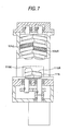
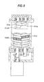
- Figs. 7 and 8 show a screw type dry vacuum pump according to a third embodiment of the invention, which differs from the second embodiment only in shapes of the suction port and the exhaust port.
- an upper, left part 111bL extends along a shape of a left transfer chamber 101cL when the left transfer chamber 101cL is moved to the exhaust port 111b
- an upper, right part 111bR extends along a shape of a right transfer chamber 101cR, just below the left transfer chamber 101cL, when the right transfer chamber 101cR is moved to the exhaust port 111b.
- a lower, left part 211aL extends along a shape of the left transfer chamber 101cL when the left transfer chamber 101cL is moved to the suction port 211a
- a lower, right part 211aR extends along a shape of the right transfer chamber 101cR, just below the left transfer chamber 101cL, when the right transfer chamber 101cR is moved to the suction port 211a.
Landscapes
- Engineering & Computer Science (AREA)
- Mechanical Engineering (AREA)
- General Engineering & Computer Science (AREA)
- Applications Or Details Of Rotary Compressors (AREA)
Applications Claiming Priority (4)
| Application Number | Priority Date | Filing Date | Title |
|---|---|---|---|
| JP2002055097 | 2002-02-28 | ||
| JP2002055097 | 2002-02-28 | ||
| JP2002196590A JP4111763B2 (ja) | 2002-07-04 | 2002-07-04 | 縦置きスクリュー式真空ポンプ |
| JP2002196590 | 2002-07-04 |
Publications (2)
| Publication Number | Publication Date |
|---|---|
| EP1340916A2 true EP1340916A2 (fr) | 2003-09-03 |
| EP1340916A3 EP1340916A3 (fr) | 2003-11-05 |
Family
ID=27736580
Family Applications (1)
| Application Number | Title | Priority Date | Filing Date |
|---|---|---|---|
| EP03004552A Withdrawn EP1340916A3 (fr) | 2002-02-28 | 2003-02-28 | Pompe à vide du type à vis |
Country Status (5)
| Country | Link |
|---|---|
| US (1) | US7052259B2 (fr) |
| EP (1) | EP1340916A3 (fr) |
| KR (1) | KR20030071585A (fr) |
| CN (1) | CN1441168A (fr) |
| TW (1) | TWI277694B (fr) |
Cited By (3)
| Publication number | Priority date | Publication date | Assignee | Title |
|---|---|---|---|---|
| WO2010143031A3 (fr) * | 2009-06-10 | 2011-05-12 | Toyota Jidosha Kabushiki Kaisha | Compresseur de fluide et véhicule à pile à combustible |
| WO2022229650A1 (fr) * | 2021-04-30 | 2022-11-03 | Edwards Limited | Stator pour pompe à vide |
| US12345261B2 (en) | 2021-04-30 | 2025-07-01 | Edwards Limited | Stator for a vacuum pump |
Families Citing this family (11)
| Publication number | Priority date | Publication date | Assignee | Title |
|---|---|---|---|---|
| KR20080084470A (ko) * | 2007-03-16 | 2008-09-19 | 삼성전자주식회사 | 컨텐트의 보호 기능을 가진 휴대용 메모리 장치 및 그휴대용 메모리 장치 생성 방법 |
| US7765993B2 (en) * | 2007-04-05 | 2010-08-03 | Gm Global Technology Operations, Inc. | Compressor inlet duct |
| US20090098003A1 (en) * | 2007-10-11 | 2009-04-16 | General Electric Company | Multiphase screw pump |
| US8096288B2 (en) * | 2008-10-07 | 2012-01-17 | Eaton Corporation | High efficiency supercharger outlet |
| KR101125568B1 (ko) * | 2009-12-14 | 2012-03-22 | 삼성모바일디스플레이주식회사 | 식각 장치 |
| CN102410219A (zh) * | 2011-11-24 | 2012-04-11 | 威海智德真空科技有限公司 | 一种立式干式螺杆真空泵 |
| TWI633612B (zh) * | 2014-06-19 | 2018-08-21 | 蘭姆研究股份公司 | 用以與處理晶圓狀物件用之設備一起使用的收集器 |
| CN104265634B (zh) * | 2014-09-19 | 2016-06-01 | 珠海格力电器股份有限公司 | 一种排气轴承座、螺杆压缩机及空调机组 |
| CN107355386B (zh) * | 2017-09-07 | 2020-12-25 | 珠海格力电器股份有限公司 | 排气组件及压缩机 |
| CN108825503B (zh) * | 2018-08-31 | 2024-01-23 | 重庆开山流体机械有限公司 | 喷油螺杆式真空泵的补气装置 |
| EP3808983B1 (fr) * | 2019-10-15 | 2024-01-03 | Ebara Corporation | Pompe à vide avec chauffage dans le couvercle latéral |
Family Cites Families (18)
| Publication number | Priority date | Publication date | Assignee | Title |
|---|---|---|---|---|
| US1191423A (en) * | 1913-01-15 | 1916-07-18 | H & S Pump Company | Pump. |
| US1635271A (en) * | 1925-08-12 | 1927-07-12 | Laval Separator Co De | Vacuum pump |
| US1821523A (en) * | 1929-01-16 | 1931-09-01 | Montelius Carl Oscar Josef | Rotary pump, compressor, or measuring device |
| US2463080A (en) * | 1945-02-17 | 1949-03-01 | Schwitzer Cummins Company | Interengaging impeller fluid pump |
| US2705922A (en) * | 1953-04-06 | 1955-04-12 | Dresser Ind | Fluid pump or motor of the rotary screw type |
| US3289600A (en) * | 1964-03-13 | 1966-12-06 | Joseph E Whitfield | Helically threaded rotors for screw type pumps, compressors and similar devices |
| SE428043C (sv) * | 1981-09-15 | 1989-12-14 | Stal Refrigeration Ab | Kompressor med radiellt inlopp till en skruvformig rotor |
| SE457822B (sv) * | 1986-11-28 | 1989-01-30 | Svenska Rotor Maskiner Ab | Foerfarande foer aastadkommande av selektivt styrda tryckpulser i en gasmassa samt anordning foer genomfoerande av foerfarandet |
| JPH01247787A (ja) * | 1988-02-29 | 1989-10-03 | Leybold Ag | 多段真空ポンプ |
| JPH0712071A (ja) | 1993-06-29 | 1995-01-17 | Ishikawajima Harima Heavy Ind Co Ltd | スクリュー型圧縮機用ケーシングの製造方法 |
| JPH07217563A (ja) | 1994-01-31 | 1995-08-15 | Ebara Corp | スクリュー流体機械の中空ロータ |
| JPH08121367A (ja) * | 1994-10-31 | 1996-05-14 | Ishikawajima Harima Heavy Ind Co Ltd | リショルムコンプレッサ用シール装置 |
| JPH1082385A (ja) | 1996-09-09 | 1998-03-31 | Ishikawajima Harima Heavy Ind Co Ltd | リショルム型コンプレッサのケーシング構造 |
| KR100386753B1 (ko) * | 1998-03-23 | 2003-06-09 | 다이코 기카이 고교 가부시키가이샤 | 드라이 진공펌프 |
| EP0952351A1 (fr) | 1998-04-21 | 1999-10-27 | Ateliers Busch S.A. | Machine volumétrique |
| IT1309299B1 (it) * | 1999-06-23 | 2002-01-22 | Samputensili Spa | Compressore rotativo a vite per gas refrigerante da utilizzare in unimpianto di condizionamento o refrigerazione di piccola potenza. |
| EP1286053A1 (fr) * | 2001-08-21 | 2003-02-26 | Ford Global Technologies, Inc., A subsidiary of Ford Motor Company | Pompe rotative avec reflux |
| US6884050B2 (en) * | 2003-04-16 | 2005-04-26 | General Motors Corporation | Roots supercharger with extended length helical rotors |
-
2003
- 2003-02-27 TW TW092104232A patent/TWI277694B/zh not_active IP Right Cessation
- 2003-02-28 US US10/377,215 patent/US7052259B2/en not_active Expired - Fee Related
- 2003-02-28 CN CN03106790A patent/CN1441168A/zh active Pending
- 2003-02-28 EP EP03004552A patent/EP1340916A3/fr not_active Withdrawn
- 2003-02-28 KR KR10-2003-0012864A patent/KR20030071585A/ko not_active Ceased
Cited By (4)
| Publication number | Priority date | Publication date | Assignee | Title |
|---|---|---|---|---|
| WO2010143031A3 (fr) * | 2009-06-10 | 2011-05-12 | Toyota Jidosha Kabushiki Kaisha | Compresseur de fluide et véhicule à pile à combustible |
| US9905865B2 (en) | 2009-06-10 | 2018-02-27 | Toyota Jidosha Kabushiki Kaisha | Fluid compressor and fuel cell vehicle |
| WO2022229650A1 (fr) * | 2021-04-30 | 2022-11-03 | Edwards Limited | Stator pour pompe à vide |
| US12345261B2 (en) | 2021-04-30 | 2025-07-01 | Edwards Limited | Stator for a vacuum pump |
Also Published As
| Publication number | Publication date |
|---|---|
| KR20030071585A (ko) | 2003-09-03 |
| TW200307089A (en) | 2003-12-01 |
| US7052259B2 (en) | 2006-05-30 |
| US20030161749A1 (en) | 2003-08-28 |
| CN1441168A (zh) | 2003-09-10 |
| EP1340916A3 (fr) | 2003-11-05 |
| TWI277694B (en) | 2007-04-01 |
Similar Documents
| Publication | Publication Date | Title |
|---|---|---|
| US7052259B2 (en) | Vacuum exhausting apparatus | |
| KR930006375B1 (ko) | 스크류 진공펌프 | |
| KR100730073B1 (ko) | 진공 배기 장치 | |
| JP6418838B2 (ja) | ドライポンプ及び排ガス処理方法 | |
| EP2715139B1 (fr) | Pompe à vide | |
| US5131825A (en) | Multi-stage vacuum pump with reaction chamber between stages | |
| JP4000611B2 (ja) | 真空排気システム | |
| EP1866076B1 (fr) | Procede et appareillage pour traiter un flux de gaz | |
| CN107850074A (zh) | 液环泵 | |
| WO2004083643A1 (fr) | Pompe volumetrique a vide | |
| JP4111763B2 (ja) | 縦置きスクリュー式真空ポンプ | |
| EP1205666A2 (fr) | Pompe à vide sèche du type à vis | |
| KR100773358B1 (ko) | 유체 노즐을 갖는 진공펌프 및 배기 시스템 | |
| JP2005171766A (ja) | ドライポンプ及びドライポンプの運転方法 | |
| US4943215A (en) | Multistage vacuum pump with bore for fouling removal | |
| JP2003322094A (ja) | 真空排気装置 | |
| JPH11270482A (ja) | 真空ポンプ | |
| JP3818709B2 (ja) | メカニカルポンプ | |
| JP4107364B2 (ja) | 真空装置 | |
| JPH0765585B2 (ja) | 半導体製造装置に用いるドライスクリュ真空ポンプ | |
| JP2008144766A (ja) | 真空装置 | |
| EP4239197B1 (fr) | Pompe à vide | |
| CN119604686A (zh) | 螺杆压缩机 | |
| CN121474128A (zh) | 一种防粉尘堆积的干式真空泵 | |
| JPS61152992A (ja) | スクリユ−流体機械 |
Legal Events
| Date | Code | Title | Description |
|---|---|---|---|
| PUAI | Public reference made under article 153(3) epc to a published international application that has entered the european phase |
Free format text: ORIGINAL CODE: 0009012 |
|
| AK | Designated contracting states |
Kind code of ref document: A2 Designated state(s): AT BE BG CH CY CZ DE DK EE ES FI FR GB GR HU IE IT LI LU MC NL PT SE SI SK TR |
|
| AX | Request for extension of the european patent |
Extension state: AL LT LV MK RO |
|
| PUAL | Search report despatched |
Free format text: ORIGINAL CODE: 0009013 |
|
| AK | Designated contracting states |
Kind code of ref document: A3 Designated state(s): AT BE BG CH CY CZ DE DK EE ES FI FR GB GR HU IE IT LI LU MC NL PT SE SI SK TR |
|
| AX | Request for extension of the european patent |
Extension state: AL LT LV MK RO |
|
| 17P | Request for examination filed |
Effective date: 20040128 |
|
| 17Q | First examination report despatched |
Effective date: 20040429 |
|
| AKX | Designation fees paid |
Designated state(s): AT BE BG CH CY CZ DE DK EE ES FI FR GB GR HU IE IT LI LU MC NL PT SE SI SK TR |
|
| STAA | Information on the status of an ep patent application or granted ep patent |
Free format text: STATUS: THE APPLICATION IS DEEMED TO BE WITHDRAWN |
|
| 18D | Application deemed to be withdrawn |
Effective date: 20090901 |