EP1340945B2 - Appareil pour traitement et préparation d'aliments avec réchauffage à gaz - Google Patents
Appareil pour traitement et préparation d'aliments avec réchauffage à gaz Download PDFInfo
- Publication number
- EP1340945B2 EP1340945B2 EP02004761A EP02004761A EP1340945B2 EP 1340945 B2 EP1340945 B2 EP 1340945B2 EP 02004761 A EP02004761 A EP 02004761A EP 02004761 A EP02004761 A EP 02004761A EP 1340945 B2 EP1340945 B2 EP 1340945B2
- Authority
- EP
- European Patent Office
- Prior art keywords
- pipe
- cooking
- heat exchanger
- burner
- cooking chamber
- Prior art date
- Legal status (The legal status is an assumption and is not a legal conclusion. Google has not performed a legal analysis and makes no representation as to the accuracy of the status listed.)
- Expired - Lifetime
Links
- 238000002485 combustion reaction Methods 0.000 title claims description 12
- 238000010438 heat treatment Methods 0.000 title description 3
- 238000010411 cooking Methods 0.000 claims description 30
- 239000000203 mixture Substances 0.000 claims description 10
- 239000007788 liquid Substances 0.000 claims description 2
- 238000009423 ventilation Methods 0.000 claims 3
- XLYOFNOQVPJJNP-UHFFFAOYSA-N water Substances O XLYOFNOQVPJJNP-UHFFFAOYSA-N 0.000 description 11
- 238000010304 firing Methods 0.000 description 4
- 230000008020 evaporation Effects 0.000 description 2
- 238000001704 evaporation Methods 0.000 description 2
- 238000005452 bending Methods 0.000 description 1
- 238000004891 communication Methods 0.000 description 1
- 238000010276 construction Methods 0.000 description 1
- 238000000034 method Methods 0.000 description 1
Images



Classifications
-
- F—MECHANICAL ENGINEERING; LIGHTING; HEATING; WEAPONS; BLASTING
- F24—HEATING; RANGES; VENTILATING
- F24C—DOMESTIC STOVES OR RANGES ; DETAILS OF DOMESTIC STOVES OR RANGES, OF GENERAL APPLICATION
- F24C15/00—Details
- F24C15/32—Arrangements of ducts for hot gases, e.g. in or around baking ovens
- F24C15/322—Arrangements of ducts for hot gases, e.g. in or around baking ovens with forced circulation
Definitions
- the present invention relates to a device for treating and preparing food, wherein the device is a cooking chamber, in which the food is treated or cooked, a motor-driven fan, which serves to circulate the cooking chamber prevailing in the cooking chamber, a burner for combustion of a Gas-air mixture is used, and has a heat exchange device having a heat exchanger tube means, which gives the fan to.
- a heat exchanger device for cooking appliances is for example from the DE 197 08 231 A1 known.
- the heat exchanger device of this prior art comprises a substantially horizontal combustion chamber, which is in communication with a heat exchanger tube into which the burned gas-air mixture is fed.
- the heat exchanger tube runs along the four sides of the cooking chamber in the direction away from the combustion chamber and reverses at the end of the fourth side by means of a cantilevered bending to again cover the same distance parallel to the pipe string leaving the combustion chamber.
- the only heat exchanger tube extends along the combustion chamber to below the cantilevered bend to dissipate the exhaust gas to the outside.
- a device for treating and preparing food namely a microwave oven
- the device has a housing with a cooking space in which the food is treated or cooked.
- the device has a motor-driven fan wheel, which serves to circulate the cooking chamber prevailing in the cooking chamber.
- a burner is provided which generates a flame for the combustion of the gas-air mixture during operation, wherein the burner is located outside the housing of the device and above it.
- the apparatus comprises a heat exchanger means having a heat exchanger tube means extending spirally in at least two surrounds around the impeller, wherein the flame generated during operation penetrates from above into the opening of the heat exchanger tube means.
- the heat exchanger tube means comprises two pipe strands which extend continuously substantially in a border or loop around the fan.
- the burner is located completely inside the housing and extends in the lower area of this only in the horizontal direction.
- the heat exchanger tube device extends the DE 298 00 523 U1 also in the vertical direction from top to bottom, so that the exhaust gas flow at the end of its path against its natural buoyancy direction must flow down.
- the present invention is therefore an object of the invention to provide a device for treating and preparing food with a cooking chamber, which is heated by gas firing, wherein the heat exchanger device provides a significantly improved heat transfer, which makes a significantly lower heating power possible, thereby significantly lower Exhaust losses occur.
- the three pipe strands are arranged triangularly in the tube longitudinal direction.
- the heat exchanger tubes additionally serve as a highly efficient evaporation device when, as provided in the present invention, water is injected via a feed line directly into the fan and transported from this to the outside becomes. Due to the radial spreading of the injected water, the water that has not yet evaporated on the outer circumference of the fan wheel is thrown onto the pipe strings and can finally evaporate there. This is advantageously also avoided that not yet evaporated water thrown to the cooking appliance inner wall.
- the pipe strands extend substantially along all four sides of the cooking chamber, but not along the burner. This will become one on the one hand realized a compact design of the cooking appliance and on the other hand increases the possible diameter of the Brennnerhunt, whereby a better and more complete combustion of the gas-air mixture is achieved.
- a flow profile is such that due to the friction of the gas at the pipe inner wall there is the lowest flow velocity and in the middle of the highest speed. This leads to a reduced heat exchanger performance, because the fast-flowing middle layer of the gas of a heat exchanger function can be little or no time spent.
- at least one pipe string preferably has all pipe strands at least one flow deflecting device. With the help of the flow deflecting device, the flowing gas can be converted from a laminar flow back into the turbulent flow, so that areas in the middle of the flow get out again and thus the efficiency of the heat exchange process is significantly increased.
- the advantage is also created that the length of the respective pipe string can be significantly shortened compared to the prior art.
- two flow diverters are spaced apart from one another in each tubing string so that multiple flow changes from a laminar flow to a turbulent flow to increase the efficiency of the heat exchanger are realized.
- the burner chamber is arranged substantially vertically, a particularly efficient combustion of the gas-air mixture is achieved, wherein the flame is directed downward in the burner chamber.
- This has the advantage that the hottest flow rate is introduced in the bottom of the cooking chamber, whereby a more uniform heat distribution is achieved in the oven.
- a guide of the exhaust gas is made possible so that the gas path in the device outside the cooking chamber can be kept as short as possible.
- FIG. 1 is shown schematically in side view, the structure of a device 1 according to the invention for treating and preparing food, in the form of a combi steamer having a housing 3.
- a cooking chamber 5 is provided, in which the food to be treated can be introduced.
- the cooking chamber 5 is closed at its front in a conventional manner with a door 7 and opened.
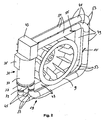
- FIG. 2 Behind a substantially vertically arranged the air baffle 25 is a radial fan 9, its construction clearly FIG. 2 is apparent.
- the radial fan 9 is driven by an asynchronous motor 11.
- the asynchronous motor 11 is arranged behind a rear wall 13 of the cooking chamber 5, and has a drive shaft 15 which is connected to the radial fan 9 for driving it.
- a supply air duct 17 is provided, in which a controllable flap 19 is arranged.
- a water inlet 21 is further provided which has a controllable inlet valve 23.
- the water inlet 21 ends in the central region of the fan 9, that is, the water to be evaporated is injected into the central region of the fan 9 and thrown radially outward due to the rotation of the fan 9, whereby already evaporates a portion of the water.
- the air guide plate 25 provided between the radial fan 9 and the cooking chamber 5 serves to distribute the air in the cooking chamber.
- a drain 27 is furthermore provided, via which liquid, in particular vapor, can drain off and which also serves to equalize the pressure.
- the heat exchanger device 29 extends around the radial fan 9 and follows substantially the inner contour of the cooking device 1.
- the heat exchanger device 29 is fed by a gas firing 31, which has a burner chamber 33.
- the burner chamber 33 is as out FIG. 2 visible, arranged vertically. It has a gas inlet 35, through which a gas-air mixture is introduced into the burner chamber 33.
- the pipe strands 41 extend in a border or loop around the impeller 9 and terminate in an exhaust collecting and dispensing device 43rd
- Each tubing string 41 has a substantially short first vertical tube section 45, a first substantially horizontal tube section 47, a second substantially vertical tube section 49 and a second substantially horizontal tube section.
- the pipe sections 45 to 51 are connected via pipe bend sections 53.
- the heat exchange gas moves in the tubing 41 before the flow deflector 55 substantially according to a flow profile 57.
- the laminar flow 57 is swirled, as indicated by the arrow 58.
- a uniform flow occurs, as indicated by the turbulent flow profile 59.
- FIG. 2 schematically only two flow deflection devices 55 are shown in the frontmost pipe string 41.
- at least two flow deflecting devices 55 are arranged in each of the pipe strands 41, wherein a further flow deflecting device 55 can be arranged in the first horizontal pipe section 47 and / or a further flow deflecting device 55 can be arranged in the second horizontal pipe section 51.
- FIG. 2 schematically illustrated embodiments of the flow deflecting device 55 in that the back pressure and thus the applied fan power can be minimized.
- the fan can be kept small, which probably promotes the compact design of the overall device and reduces the energy required for the operation of the fan.
- FIG. 1 In FIG. 1 is the triangular arrangement of the pipe strands 41 clearly visible.
- the ejected from the fan 9 in the radial direction of water strikes the pipe strands 41, wherein as from FIG. 1 As can be seen, these completely cover the radial application space of the fan.
- the ejected water strikes the pipe strands 41 and not on the inner wall 6 of the cooking appliance, whereby an optimal evaporation of the introduced water is achieved.
- FIG. 4 the gas firing 31 is shown schematically.
- a substantially circular grid 61 is arranged, and the gas-air mixture, which enters the burner chamber 33 via the gas inlet 35, flows through the grid 61.
- an ignition device 63 which is the gas-air mixture ignites and a dashed illustrated Brennkegel 65 is formed, which extends vertically downwards in the burner chamber 33.
- the arrangement of the flame cone 65 has the advantage of a substantially complete combustion of the gas-air mixture, wherein due to the grid, the flame cone 65 composed of a plurality of individual flames due to the lattice structure of the grid 61 composed.
- the present invention thus provides a device for treating and preparing foodstuffs with a gas firing system designed in a very advantageous manner and an advantageously designed heat exchanger device.
Landscapes
- Engineering & Computer Science (AREA)
- Chemical & Material Sciences (AREA)
- Combustion & Propulsion (AREA)
- Mechanical Engineering (AREA)
- General Engineering & Computer Science (AREA)
- Baking, Grill, Roasting (AREA)
- Heat-Exchange Devices With Radiators And Conduit Assemblies (AREA)
Claims (4)
- Appareil (1) pour le traitement et la préparation de produits alimentaires comprenant :un boîtier (3) avec un espace de cuisson (5), dans lequel sont traités ou cuits les produits alimentaires,une roue de ventilateur (9) entraînée par moteur, qui sert à brasser l'atmosphère régnant dans l'espace de cuisson (5),un brûleur (31) qui produit une flamme en fonctionnement pour la combustion d'un mélange air-gaz et qui est disposé complètement à l'intérieur du boîtier (3), etun dispositif d'échange de chaleur (29), qui présente un système de tubes d'échange de chaleur (41), qui entoure la roue de ventilateur (9),caractérisé en ce quele système de tubes d'échange de chaleur présente trois lignes de tubes (41) qui s'étendent en continu essentiellement en une bordure périphérique ou boucle autour de la roue de ventilateur (9), et que les trois lignes de tubes (41) sont disposées en triangle dans la direction longitudinale des tubes,que l'appareil (1) présente une zone inférieure qui comporte une issue (27) au travers de laquelle peut s'échapper du liquide, en particulier des buées,que la chambre de combustion (33) est disposée essentiellement de façon verticale et dirigée sur la zone inférieure de l'appareil (1), etque la flamme (65) produite en fonctionnement est orientée vers le bas dans la chambre de combustion (33).
- Appareil de cuisson suivant la revendication 1, caractérisé en ce que les lignes de tubes (41) s'étendent essentiellement le long des quatre côtés de l'espace de cuisson, mais pas le long du brûleur (31).
- Appareil de cuisson suivant l'une des revendications 1 et 2, caractérisé en ce qu'au moins un dispositif de déviation d'écoulement (55) est disposé dans au moins une ligne de tube (41).
- Appareil de cuisson suivant la revendication 3, caractérisé en ce qu'au moins deux dispositifs de déviation d'écoulement (55) sont disposés à distance mutuelle dans chaque ligne de tube (41).
Priority Applications (5)
| Application Number | Priority Date | Filing Date | Title |
|---|---|---|---|
| EP02004761A EP1340945B2 (fr) | 2002-03-01 | 2002-03-01 | Appareil pour traitement et préparation d'aliments avec réchauffage à gaz |
| DE50208407T DE50208407D1 (de) | 2002-03-01 | 2002-03-01 | Gerät zum Behandeln und Zubereiten von Nahrungsmitteln mit gasbefeuerter Heizung |
| DK02004761.9T DK1340945T4 (da) | 2002-03-01 | 2002-03-01 | Apparat til behandling og tilberedning af fødevarer med gasfyret opvarmning samt varmeudveksleranordning til et sådant apparat |
| US10/375,382 US7325480B2 (en) | 2002-03-01 | 2003-02-27 | Apparatus for treating and preparing food by gas-fired heating and a heat exchange device for such an apparatus |
| JP2003054629A JP2003262339A (ja) | 2002-03-01 | 2003-02-28 | ガスの火による加熱によって食品を処理して準備する装置、及び、そのような装置のための熱交換手段 |
Applications Claiming Priority (1)
| Application Number | Priority Date | Filing Date | Title |
|---|---|---|---|
| EP02004761A EP1340945B2 (fr) | 2002-03-01 | 2002-03-01 | Appareil pour traitement et préparation d'aliments avec réchauffage à gaz |
Publications (3)
| Publication Number | Publication Date |
|---|---|
| EP1340945A1 EP1340945A1 (fr) | 2003-09-03 |
| EP1340945B1 EP1340945B1 (fr) | 2006-10-11 |
| EP1340945B2 true EP1340945B2 (fr) | 2009-08-26 |
Family
ID=27675677
Family Applications (1)
| Application Number | Title | Priority Date | Filing Date |
|---|---|---|---|
| EP02004761A Expired - Lifetime EP1340945B2 (fr) | 2002-03-01 | 2002-03-01 | Appareil pour traitement et préparation d'aliments avec réchauffage à gaz |
Country Status (5)
| Country | Link |
|---|---|
| US (1) | US7325480B2 (fr) |
| EP (1) | EP1340945B2 (fr) |
| JP (1) | JP2003262339A (fr) |
| DE (1) | DE50208407D1 (fr) |
| DK (1) | DK1340945T4 (fr) |
Families Citing this family (33)
| Publication number | Priority date | Publication date | Assignee | Title |
|---|---|---|---|---|
| DK1340945T4 (da) * | 2002-03-01 | 2010-01-25 | Eloma Gmbh Innovative Koch Und | Apparat til behandling og tilberedning af fødevarer med gasfyret opvarmning samt varmeudveksleranordning til et sådant apparat |
| DE202004016446U1 (de) * | 2004-10-23 | 2006-03-23 | Wss Gmbh | Wärmetauschereinrichtung |
| CN102771523B (zh) | 2008-01-28 | 2015-04-22 | 杜克制造公司 | 对流式炉 |
| DE202008010227U1 (de) | 2008-07-31 | 2009-12-10 | Klouda, Jaroslav, Dipl.-Ing. | Gasvormischbrenner und Wärmetauschersystem für Koch-, Gar- und andere thermische Geräte |
| IT1392974B1 (it) * | 2009-02-17 | 2012-04-02 | Premark Feg Llc | Scambiatore di calore per un dispositivo di processamento di cibo e forno provvisto dello stesso |
| IT1402171B1 (it) * | 2010-07-21 | 2013-08-28 | Premark Feg Llc | Dispositivo di processamento di cibo, in particolare forno, provvisto di uno scambiatore di calore migliorato |
| EP2420744A1 (fr) * | 2010-08-18 | 2012-02-22 | Eloma GmbH | Echangeur thermique à gaz pour appareils de traitement d'aliments et un tel appareil |
| KR101278621B1 (ko) | 2011-12-13 | 2013-07-05 | 이노엔 주식회사 | 조리기기용 열교환기 |
| KR101381561B1 (ko) * | 2012-10-26 | 2014-04-04 | 린나이코리아 주식회사 | 열교환기 및 이를 구비한 컨벡션 오븐 |
| KR101370415B1 (ko) * | 2012-10-29 | 2014-03-06 | 린나이코리아 주식회사 | 경사 배열식 열교환기 및 이를 구비한 컨벡션 오븐 |
| KR101381562B1 (ko) * | 2012-10-31 | 2014-04-04 | 린나이코리아 주식회사 | 타원 단면식 열교환기 및 이를 구비한 컨벡션 오븐 |
| KR101428870B1 (ko) * | 2012-11-27 | 2014-08-14 | 엘지전자 주식회사 | 가스 오븐 레인지 |
| US9372005B2 (en) | 2012-11-30 | 2016-06-21 | Alto-Shaam, Inc. | Heat exchanger for oven |
| WO2014196676A1 (fr) * | 2013-06-07 | 2014-12-11 | 이노엔 주식회사 | Échangeur de chaleur pour appareil de cuisson |
| KR101564505B1 (ko) * | 2014-04-03 | 2015-10-29 | 엘지전자 주식회사 | 조리기기 |
| USD762289S1 (en) * | 2014-07-15 | 2016-07-26 | Dometic Sweden Ab | Heat exchanger |
| KR101663888B1 (ko) | 2015-02-13 | 2016-10-14 | 엘지전자 주식회사 | 조리기기 |
| USD787041S1 (en) | 2015-09-17 | 2017-05-16 | Whirlpool Corporation | Gas burner |
| US10837651B2 (en) | 2015-09-24 | 2020-11-17 | Whirlpool Corporation | Oven cavity connector for operating power accessory trays for cooking appliance |
| KR101721832B1 (ko) * | 2015-11-23 | 2017-03-31 | 인하대학교 산학협력단 | 오븐용 열교환기 |
| US11777190B2 (en) | 2015-12-29 | 2023-10-03 | Whirlpool Corporation | Appliance including an antenna using a portion of appliance as a ground plane |
| US10145568B2 (en) | 2016-06-27 | 2018-12-04 | Whirlpool Corporation | High efficiency high power inner flame burner |
| KR101742185B1 (ko) | 2016-10-25 | 2017-05-30 | 주식회사 효신테크 | 열교환기 |
| US10551056B2 (en) | 2017-02-23 | 2020-02-04 | Whirlpool Corporation | Burner base |
| US10451290B2 (en) | 2017-03-07 | 2019-10-22 | Whirlpool Corporation | Forced convection steam assembly |
| US10660162B2 (en) | 2017-03-16 | 2020-05-19 | Whirlpool Corporation | Power delivery system for an induction cooktop with multi-output inverters |
| CN107216887B (zh) * | 2017-06-26 | 2023-08-04 | 中冶华天工程技术有限公司 | 焦炉荒煤气上升管换热器 |
| US10627116B2 (en) | 2018-06-26 | 2020-04-21 | Whirlpool Corporation | Ventilation system for cooking appliance |
| US10619862B2 (en) | 2018-06-28 | 2020-04-14 | Whirlpool Corporation | Frontal cooling towers for a ventilation system of a cooking appliance |
| US10837652B2 (en) | 2018-07-18 | 2020-11-17 | Whirlpool Corporation | Appliance secondary door |
| CN110715520A (zh) * | 2019-09-09 | 2020-01-21 | 陈国� | 一种环保节能的烘干装置 |
| US12305886B2 (en) * | 2020-12-14 | 2025-05-20 | Rheem Manufacturing Company | Heating systems with unhoused centrifugal fan and wraparound heat exchanger |
| EP4014806A1 (fr) * | 2020-12-18 | 2022-06-22 | Koninklijke Philips N.V. | Friteuse à air |
Citations (1)
| Publication number | Priority date | Publication date | Assignee | Title |
|---|---|---|---|---|
| US5556566A (en) † | 1994-06-22 | 1996-09-17 | Zanussi Grandi Impianti S.P.A. | Combined gas-microwave cooking oven with steam operation |
Family Cites Families (15)
| Publication number | Priority date | Publication date | Assignee | Title |
|---|---|---|---|---|
| US3889099A (en) * | 1974-07-31 | 1975-06-10 | Gen Electric | Door cooling system |
| US4110916A (en) * | 1976-08-30 | 1978-09-05 | Bemrose Harold E | Forced air food drier |
| US5215000A (en) * | 1988-03-29 | 1993-06-01 | A.R.M.I.N.E.S. | Method and apparatus for thermal treatment of alimentary substances |
| FR2650061B1 (fr) * | 1989-07-19 | 1991-11-15 | Gaz De France | Four perfectionne fonctionnant a la vapeur et/ou au gaz |
| DE4125696C1 (en) * | 1991-08-02 | 1993-02-18 | Eloma Gmbh Grosskuechentechnik, 8031 Maisach, De | Steam cooker with air fan wheel - vaporises water before reaching heaters with water inlets controlled by valves |
| IT1253697B (it) * | 1991-08-05 | 1995-08-22 | Zanussi Grandi Impianti Spa | Forno di cottura a gas a convezione forzata. |
| IT231984Y1 (it) * | 1993-11-15 | 1999-08-10 | Zanussi Grandi Impianti Spa | Forno di cottura dotato di dispositivo perfezionato di controllo vapore |
| FR2728656B1 (fr) * | 1994-12-21 | 2000-02-18 | Fagor S Coop Ltda | Four commercial de cuisinage combine a gaz |
| DE29800523U1 (de) | 1998-01-14 | 1999-05-12 | Greuel, Peter, 53123 Bonn | Umluftofen |
| DE19824172A1 (de) * | 1998-05-29 | 1999-12-09 | Rational Gmbh | Gargerät mit Energiespeicher- und Energieentnahmesystem |
| IT1311159B1 (it) * | 1999-11-30 | 2002-03-04 | Angelo Grandi Cucine Spa | Dispositivo scambiatore di calore per forni adibiti alla cottura dialimenti |
| NL1014044C2 (nl) * | 2000-01-10 | 2001-07-19 | Levens Group B V | Door gasbrander verwarmde oven. |
| IT1315481B1 (it) * | 2000-07-25 | 2003-02-18 | Gierre Srl | Forno a convezione forzata per la cottura di alimenti |
| DK1340945T4 (da) * | 2002-03-01 | 2010-01-25 | Eloma Gmbh Innovative Koch Und | Apparat til behandling og tilberedning af fødevarer med gasfyret opvarmning samt varmeudveksleranordning til et sådant apparat |
| DK1342414T3 (da) * | 2002-03-07 | 2006-10-02 | Eloma Gmbh | Fremgangsmåde til måling af fugtighed i et apparat til behandling og tilberedelse af födevarer såvel som apparat til behandling og tilberedelse af födevarer |
-
2002
- 2002-03-01 DK DK02004761.9T patent/DK1340945T4/da active
- 2002-03-01 EP EP02004761A patent/EP1340945B2/fr not_active Expired - Lifetime
- 2002-03-01 DE DE50208407T patent/DE50208407D1/de not_active Expired - Lifetime
-
2003
- 2003-02-27 US US10/375,382 patent/US7325480B2/en not_active Expired - Fee Related
- 2003-02-28 JP JP2003054629A patent/JP2003262339A/ja active Pending
Patent Citations (1)
| Publication number | Priority date | Publication date | Assignee | Title |
|---|---|---|---|---|
| US5556566A (en) † | 1994-06-22 | 1996-09-17 | Zanussi Grandi Impianti S.P.A. | Combined gas-microwave cooking oven with steam operation |
Also Published As
| Publication number | Publication date |
|---|---|
| DK1340945T3 (da) | 2007-02-19 |
| US20030164096A1 (en) | 2003-09-04 |
| DK1340945T4 (da) | 2010-01-25 |
| DE50208407D1 (de) | 2006-11-23 |
| EP1340945B1 (fr) | 2006-10-11 |
| EP1340945A1 (fr) | 2003-09-03 |
| JP2003262339A (ja) | 2003-09-19 |
| US7325480B2 (en) | 2008-02-05 |
Similar Documents
| Publication | Publication Date | Title |
|---|---|---|
| EP1340945B1 (fr) | Appareil pour traitement et préparation d'aliments avec réchauffage à gaz | |
| DE60018118T2 (de) | Kombinierter ofen mit dreistufigem wasserzerstäuber | |
| DE69200704T2 (de) | Gasbeheizter Ofen mit erzwungener Konvektion. | |
| DE60027482T2 (de) | Verfahren und vorrichtung zur erzeugung von konvektionsenergie | |
| DE724998C (de) | Druckaustauscher, z. B. fuer Kaeltemaschinen | |
| DE1426648B2 (de) | Schnelldampferzeuger | |
| DE1802196A1 (de) | Brennereinheit fuer Heizkoerper | |
| DE60018251T2 (de) | Wärmetauscher für Nahrungsmittelofen. | |
| DE1778150A1 (de) | Gasheizgeraet | |
| EP1010384B1 (fr) | Appareil de cuisson et méthode pour réchauffer un produit de cuisson à l'aide de vapeur | |
| EP0128463A2 (fr) | Appareil de chauffage des locaux pour des locaux de petite dimension | |
| DE20003485U1 (de) | Backofen mit beheiztem Dampferzeuger | |
| EP1321720A1 (fr) | Dispositif d' échangeur de chaleur | |
| DE3428330C2 (de) | Backofen | |
| DE857684C (de) | Heizkessel mit von einem Wassermantel umgebener Verbrennungskammer | |
| DE2508727A1 (de) | Waermetauscher | |
| EP0406173B1 (fr) | Chaudière | |
| DE19731544A1 (de) | Dampfgarofen mit einer Dampferzeugereinheit | |
| EP2661585B1 (fr) | Ensemble brûleur pour un appareil mobile pouvant être chauffé, notamment pour un appareil de cuisson mobile | |
| DE2943590A1 (de) | Verfahren zum befeuern eines kessels und kessel zur durchfuehrung des verfahrens | |
| DE10220624A1 (de) | Gemischter Backofen mit hoher Leistung zum Backen mit Konvektion und/oder Dämpfen | |
| DE60002592T2 (de) | Gasdurchlaufofen insbesondere für kautschuk produkte | |
| EP2551603A2 (fr) | Système de chauffage de salle avec technique de valeur de combustion | |
| DE1579797C3 (de) | Wandlufterhitzer | |
| DE1937034U (de) | Wandlufterhitzer. |
Legal Events
| Date | Code | Title | Description |
|---|---|---|---|
| PUAI | Public reference made under article 153(3) epc to a published international application that has entered the european phase |
Free format text: ORIGINAL CODE: 0009012 |
|
| AK | Designated contracting states |
Kind code of ref document: A1 Designated state(s): AT BE CH CY DE DK ES FI FR GB GR IE IT LI LU MC NL PT SE TR |
|
| AX | Request for extension of the european patent |
Extension state: AL LT LV MK RO SI |
|
| 17P | Request for examination filed |
Effective date: 20040217 |
|
| AKX | Designation fees paid |
Designated state(s): BE DE DK IT NL |
|
| 17Q | First examination report despatched |
Effective date: 20050311 |
|
| GRAP | Despatch of communication of intention to grant a patent |
Free format text: ORIGINAL CODE: EPIDOSNIGR1 |
|
| RTI1 | Title (correction) |
Free format text: DEVICE FOR TREATING AND PREPARING FOODSTUFFS WITH GAS COMBUSTION HEATING |
|
| GRAS | Grant fee paid |
Free format text: ORIGINAL CODE: EPIDOSNIGR3 |
|
| GRAA | (expected) grant |
Free format text: ORIGINAL CODE: 0009210 |
|
| RAP1 | Party data changed (applicant data changed or rights of an application transferred) |
Owner name: ELOMA GMBH - INNOVATIVE KOCH- UND BACKTECHNIK |
|
| AK | Designated contracting states |
Kind code of ref document: B1 Designated state(s): BE DE DK IT NL |
|
| REF | Corresponds to: |
Ref document number: 50208407 Country of ref document: DE Date of ref document: 20061123 Kind code of ref document: P |
|
| PLBI | Opposition filed |
Free format text: ORIGINAL CODE: 0009260 |
|
| PLAX | Notice of opposition and request to file observation + time limit sent |
Free format text: ORIGINAL CODE: EPIDOSNOBS2 |
|
| 26 | Opposition filed |
Opponent name: ANGELO PO GRANDI CUCINE S.P.A. Effective date: 20070710 |
|
| NLR1 | Nl: opposition has been filed with the epo |
Opponent name: ANGELO PO GRANDI CUCINE S.P.A. |
|
| PLAF | Information modified related to communication of a notice of opposition and request to file observations + time limit |
Free format text: ORIGINAL CODE: EPIDOSCOBS2 |
|
| PLBP | Opposition withdrawn |
Free format text: ORIGINAL CODE: 0009264 |
|
| PLBB | Reply of patent proprietor to notice(s) of opposition received |
Free format text: ORIGINAL CODE: EPIDOSNOBS3 |
|
| PUAH | Patent maintained in amended form |
Free format text: ORIGINAL CODE: 0009272 |
|
| STAA | Information on the status of an ep patent application or granted ep patent |
Free format text: STATUS: PATENT MAINTAINED AS AMENDED |
|
| 27A | Patent maintained in amended form |
Effective date: 20090826 |
|
| AK | Designated contracting states |
Kind code of ref document: B2 Designated state(s): BE DE DK IT NL |
|
| NLR2 | Nl: decision of opposition |
Effective date: 20090826 |
|
| NLR3 | Nl: receipt of modified translations in the netherlands language after an opposition procedure | ||
| REG | Reference to a national code |
Ref country code: DK Ref legal event code: T4 |
|
| REG | Reference to a national code |
Ref country code: DE Ref legal event code: R082 Ref document number: 50208407 Country of ref document: DE Representative=s name: VON LIERES BRACHMANN SCHULZE PATENTANWAELTE, DE Ref country code: DE Country of ref document: DE |
|
| PGFP | Annual fee paid to national office [announced via postgrant information from national office to epo] |
Ref country code: NL Payment date: 20140320 Year of fee payment: 13 |
|
| PGFP | Annual fee paid to national office [announced via postgrant information from national office to epo] |
Ref country code: BE Payment date: 20140320 Year of fee payment: 13 |
|
| REG | Reference to a national code |
Ref country code: NL Ref legal event code: MM Effective date: 20150401 |
|
| PG25 | Lapsed in a contracting state [announced via postgrant information from national office to epo] |
Ref country code: NL Free format text: LAPSE BECAUSE OF NON-PAYMENT OF DUE FEES Effective date: 20150401 |
|
| PG25 | Lapsed in a contracting state [announced via postgrant information from national office to epo] |
Ref country code: BE Free format text: LAPSE BECAUSE OF NON-PAYMENT OF DUE FEES Effective date: 20150331 |
|
| PGFP | Annual fee paid to national office [announced via postgrant information from national office to epo] |
Ref country code: IT Payment date: 20200325 Year of fee payment: 19 Ref country code: DK Payment date: 20200323 Year of fee payment: 19 |
|
| PGFP | Annual fee paid to national office [announced via postgrant information from national office to epo] |
Ref country code: DE Payment date: 20200327 Year of fee payment: 19 |
|
| REG | Reference to a national code |
Ref country code: DE Ref legal event code: R119 Ref document number: 50208407 Country of ref document: DE |
|
| REG | Reference to a national code |
Ref country code: DK Ref legal event code: EBP Effective date: 20210331 |
|
| PG25 | Lapsed in a contracting state [announced via postgrant information from national office to epo] |
Ref country code: DE Free format text: LAPSE BECAUSE OF NON-PAYMENT OF DUE FEES Effective date: 20211001 |
|
| PG25 | Lapsed in a contracting state [announced via postgrant information from national office to epo] |
Ref country code: IT Free format text: LAPSE BECAUSE OF NON-PAYMENT OF DUE FEES Effective date: 20210301 Ref country code: DK Free format text: LAPSE BECAUSE OF NON-PAYMENT OF DUE FEES Effective date: 20210331 |