EP1340986A2 - Boítier d'un compteur d'électricité - Google Patents
Boítier d'un compteur d'électricité Download PDFInfo
- Publication number
- EP1340986A2 EP1340986A2 EP03003411A EP03003411A EP1340986A2 EP 1340986 A2 EP1340986 A2 EP 1340986A2 EP 03003411 A EP03003411 A EP 03003411A EP 03003411 A EP03003411 A EP 03003411A EP 1340986 A2 EP1340986 A2 EP 1340986A2
- Authority
- EP
- European Patent Office
- Prior art keywords
- plug
- wires
- terminals
- wire
- socket terminal
- Prior art date
- Legal status (The legal status is an assumption and is not a legal conclusion. Google has not performed a legal analysis and makes no representation as to the accuracy of the status listed.)
- Withdrawn
Links
- 230000005611 electricity Effects 0.000 title 1
- 238000006073 displacement reaction Methods 0.000 claims description 3
- 239000011810 insulating material Substances 0.000 claims description 2
- 238000007792 addition Methods 0.000 description 1
- 230000008878 coupling Effects 0.000 description 1
- 238000010168 coupling process Methods 0.000 description 1
- 238000005859 coupling reaction Methods 0.000 description 1
- 238000009434 installation Methods 0.000 description 1
- 239000012774 insulation material Substances 0.000 description 1
- 238000000034 method Methods 0.000 description 1
- 238000012986 modification Methods 0.000 description 1
- 230000004048 modification Effects 0.000 description 1
- 238000006467 substitution reaction Methods 0.000 description 1
Images


Classifications
-
- G—PHYSICS
- G01—MEASURING; TESTING
- G01R—MEASURING ELECTRIC VARIABLES; MEASURING MAGNETIC VARIABLES
- G01R11/00—Electromechanical arrangements for measuring time integral of electric power or current, e.g. of consumption
- G01R11/02—Constructional details
- G01R11/04—Housings; Supporting racks; Arrangements of terminals
Definitions
- the present invention relates to a distribution board equipped with an uninterruptible socket terminal block, which enables a watt-hour meter to be replaced without interrupting the supply of indoor power, and more particularly to a distribution board equipped with an uninterruptible socket terminal block, which enables a watt-hour meter equipped thereon to be easily replaced, and enables drop wires and indoor power wires to be easily separated from and connected to the watt-hour meter by using an associated power-converting plugs, without necessity of interrupting supply of indoor power, without regard to the confined space of the distribution board and the standard of terminals applied in the watt-hour meter.
- electric power necessary for all household consumers, is introduced to an indoor distribution board from drop wires of an electric pole connected to an electric power company's distribution lines through an indoor watt-hour meter.
- An installation of drop wires between the electric pole and a consumer's watt-hour meter in the distribution board is usually the responsibility of the electric power company, while a wiring operation of indoor electric wires leading out of the watt-hour meter is the responsibility of a consumer and is carried out by a usual electrical contractor.
- the watt-hour meter for measuring the quantity of electric energy consumed by the consumer is installed by the electric power company. After about seven years of use, the used watt-hour meter mounted on the distribution board is replaced by the electric power company with a new one. At this point, the electric power supplied to the consumer's house must be interrupted in order to replace the used watt-hour meter.
- the drop wires, for conducting primary electrical power to the watt-hour meter, and the indoor power wires, for drawing secondary electrical power out of the watt-hour meter must be separated from the watt-hour meter and again connected thereto.
- an electrician has to perform procedures of separating the drop wires and the indoor power wires from terminals of a terminal block, stripping coverings from both ends of the drop wires and the indoor power wires to expose conducting core wires thereof, and again connecting the exposed intermediate wires to the corresponding terminals of the terminal block.
- safety hazards due to handling of electric wires and inconvenience due to interruption of supply of indoor electric power inevitably accompany such operation.
- an object of the present invention is to provide a distribution board equipped with an uninterruptible socket terminal block, which enables a watt-hour meter equipped thereon to be easily replaced and enables drop wires and indoor power wires to be easily separated from and connected to the watt-hour meter by using its associated power-converting plug, without necessity of interrupting the supply of primary electric power to the consumer's house, without regard to the confined space of the distribution board or the standard of terminals applied in the watt-hour meter.
- the present invention provides a distribution board comprising: an uninterruptible socket terminal block including a plurality of socket terminal connectors, each of socket terminal connectors having a pair of wire-connector terminals extending in directions opposite each other and a plug-connector terminal extending from the conjunction portion between the pair of wire-connector terminals in a direction perpendicular to the pair of wire-connector terminals, the wire-connectors, which extend in one direction, being connected to drop wires for conducting primary electric power and indoor power wires for conducting secondary electric power, and the other wire-connectors, which extend in the other direction, being connected to intermediate wires for connecting the drop wires and the indoor power wires to terminals of a watt-hour meter; and a power-converting plug including a plurality of plug terminals to be connected to the corresponding plug-connector terminals of the socket terminal connectors, half of the plurality of plug terminals being connected to the other half of the plurality of plug terminals via plug-connecting wires;
- the socket terminal block may be made from an insulating material.
- the socket terminal block may be provided at the central line thereof with plug-inserting holes to receive the corresponding plug terminals and the corresponding plug-connector terminals, and may be provided at both side surfaces thereof with wire-inserting holes to receive the corresponding wire-connector terminals.
- the wire-connector terminals of the socket terminal connectors may include threaded holes into which screws are tightened to hold the wires inserted into the wire-connector terminals, and each pair of wire-connector terminals are provided at the conjunction portion thereof with a plug-positioning groove that the plug-connector terminal is placed thereinto and fixed thereto.
- the distribution board may include a wire-retainer provided at covering portions of the intermediate wires connected to the drop wires and the indoor power wires, in order to hold the wires without displacement of the wires.
- the distribution board may include a wire-adjusting unit, which comprises upper and lower housings provided with a plurality of recesses at facing surfaces thereof and adapted to be tightened to each other by fastening means, and a plurality of pairs of plug terminals disposed between the corresponding recesses of the upper and lower housings and extending toward both the socket terminal block and the watt-hour meter, whereby each pair of plug terminals are properly fixed at desired positions between the upper and lower housings according to a distance defined between the watt-hour meter and the socket terminal block.
- a wire-adjusting unit which comprises upper and lower housings provided with a plurality of recesses at facing surfaces thereof and adapted to be tightened to each other by fastening means, and a plurality of pairs of plug terminals disposed between the corresponding recesses of the upper and lower housings and extending toward both the socket terminal block and the watt-hour meter, whereby each pair of plug terminals are properly fixed at desired positions between the upper and lower housings according to a distance defined between the
- FIG. 1 shows a distribution board according to the present invention, in which terminals of an uninterruptible socket terminal block 20 are connected to terminals of a meter terminal block 11 of a watt-hour meter 10, and
- FIG. 2 shows a distribution board according to the present invention, in which an additional power-converting plug 40 is connected to the socket terminal block 20, so as to replace the watt-hour meter 10 without interruption of the supply of primary electric power from a drop wire to an indoor power wire 13.
- FIG. 3 is an exploded perspective view showing a coupling structure of the socket terminal block 20 and the power-converting plug 40 according to the present invention
- FIG. 4 shows a wire-retainer 43 adapted to hold an intermediate wire 14 connected to the meter terminal block 11 of the watt-hour meter 10 to prevent displacement of the electric wire, according to the present invention.
- the distribution board according to the present invention is intended to allow the watt-hour meter 10 to be replaced without disconnecting the indoor power wires 13.
- the primary drop wires 12 for conducting primary electric power and the intermediate wires 14 for conducting secondary electric power are inserted into wire-inserting holes 34 of wire-connector terminals 35 of a socket terminal connector unit 30 embedded in the socket terminal block 20, and then connected thereto by screws passing through threaded holes 26 formed at the wire-connector terminals 35.
- Terminals of the meter terminal block 11 are connected to the wire-connector terminals 35 from the direction of the watt-hour meter 10, in the same connecting manner.
- the socket terminal block 20 is provided with the power-converting plug 40, such that plug terminals 41 of the power-converting plug 40 are connected to corresponding plug-connector terminals 31 of the socket terminal block 20.
- the plug terminals 41 for the drop wires 12 are connected to the corresponding plug terminals 41 for the indoor power wires 13 by plug-connecting wires 42.
- the socket terminal block 20 which is made from an insulation material, is provided along the central line thereof with vertical plug-inserting holes 21 into which the plug terminals 41 of the power-converting plug 40 are inserted.
- the socket terminal block 20 is further provided at its upper surface with screw recesses 22 to be positioned at both sides of the plug-inserting holes 21, and is provided at its front and rear side surfaces with horizontal wire-inserting holes 23.
- the socket terminal block 20 also includes block-mounting wings 24 at both its sides.
- the socket terminal connector unit 30 embedded in the socket terminal block 20 includes the vertical plug-connector terminals 31 along the central line thereof, into which the plug terminals 41 of the power-converting plug 40 are inserted, and the horizontal wire-connector terminals 35 extending from the corresponding plug-connector terminals 31 forward and backward, into which the exposed core wires of the drop wire 12, the indoor power wire 13 and the intermediate wires 14 are inserted.
- the horizontal wire-connector terminals 35 which extend from the plug-connector terminals 31 forward and backward, are provided with threaded holes 36, so as to fix the wires 12, 13 and 14 thereto via screws passing through the threaded holes 36.
- Each of the wire-connector terminals 35 is provided at its center portion with a plug-positioning groove 33, so that the plug-connector terminal 31 is placed in the plug-positioning groove 33 and joined thereto by screws.
- the distribution according to the present invention may be additionally provided with a wire-retainer 43, which surrounds the unexposed covering portions of the intermediate wires 14.
- the drop wires 12 and the indoor power wires 13 are connected to the terminals of the meter terminal block 11 positioned under the watt-hour meter 10 mounted on the distribution board 16, via the socket terminal block 20.
- the socket terminal block 20 is preferably positioned below the watt-hour meter 10, so as to allow the watt-hour meter 10 to be easily replaced regardless of the confined space of the distribution board 16 or the standard of the terminals applied in the watt-hour meter 10, the socket terminal block 20 may be installed outside the distribution board 16 if necessary.
- the distribution board 16 may be provided with the wire-retainer 43 so as to cause the intermediate wires 14 of the drop wires 12 and the indoor power wires 13 to be firmly connected to the terminals of the meter terminal block 11 of the watt-hour meter 10. Therefore, since the wire-retainer 43 firmly holds covering portions 15 of the intermediate wires 14, the intermediate wires 14 can be uniformly arranged and stably maintained between the socket terminal block 20 and the meter terminal block 11.
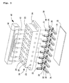
- the wire-adjusting unit 50 which may be used in place of the wire-retainer 43 in order to adjust lengths of the intermediate wires 14 when there are differences between the lengths of the intermediate wires 14 between the meter terminal block 11 of the watt-hour meter 10 and the socket terminal block 20.
- the wire-adjusting unit 50 includes a pair of upper and lower housings 52, each of which has a plurality of front terminal recesses 55 and a plurality of rear terminal recesses 55.
- a plurality of pairs of plug terminals 53 are disposed on the front and rear terminal recesses 55 of the lower housings 52, such that the rear plug terminals 53 to be connected to the terminals of the meter terminal block 11 are positioned according to the size of the meter terminal block 11.
- connecting pieces 56 each having a through hole 51, are placed upon the stepped portions 54 of the front and rear plug terminals 53, and the upper housing 52 is placed upon the lower housing 52 with the plug terminals 53 and the connecting pieces 56 thereon. Subsequently, the upper and lower housings 52 are tightened to each other by bolts passing through the through holes 51.
- the drop wires 12 and the indoor power wires 13 can be stably connected to the terminals of the meter terminal block 11 of the watt-hour meter 10 via the socket terminal block 20. More specifically, stripped wires of the drop wires 12 and the indoor power wires 13 are inserted into the wire-inserting holes 34 of the wire-connector terminals 35 of the socket terminal connector unit 30 embedded in the socket terminal block 20, and then firmly fixed thereto by tightening screws through the threaded holes 36. Thereafter, the intermediate wires 14 are also connected between the terminals of the socket terminal block 20 and the terminals of the meter terminal block 11, in the same manner as the drop wires 12 and the indoor power wires 13.
- the plug terminals 41 of the power-converting plug 40 are first inserted into the plug-inserting holes 21 of the socket terminal block 20, as shown in FIGS. 2 and 3. Consequently, electrical power supplied from the drop wires 12 is not only transmitted to the terminals of the meter terminal block 11 of the watt-hour meter 10 through the wire-connector terminals 35 of the socket terminal block 20, but also transmitted to the indoor power wires 13 through the plug terminals 41 of the power-converting plug 40.
- the watt-hour meter 10 can be easily replaced by joining the power-converting plug 40 to the socket terminal block 20, without interruption of the supply of electric power.
- the power-converting plug 40 must be prepared to meet the standard applied to the socket terminal block 20.
- the intermediate wires 14 can be connected between the watt-hour meter 10 and the socket terminal block 20 via the wire-adjusting unit 50, as shown in FIG. 5. This is simply achieved by adjusting positions of the plug terminals 53 provided at any one of both sides of the wire-adjusting unit 50.
- the present invention provides a distribution board equipped with an uninterruptible socket terminal block, which allows a watt-hour meter to be easily replaced without interrupting the supply of primary electric power from a drop wire to an indoor power wire. Therefore, the distribution board according to the present invention can solve various problems, i.e., inconvenience due to interruption of the supply of electric power to a consumer's house, consumer's complaints regarding the interruption of the supply of electric power, several visitations and operations for adapting a new watt-hour meter having a different standard to a current distribution board, and increase of cost due to the above problems.
Landscapes
- Physics & Mathematics (AREA)
- General Physics & Mathematics (AREA)
- Connections Arranged To Contact A Plurality Of Conductors (AREA)
- Distribution Board (AREA)
Applications Claiming Priority (2)
| Application Number | Priority Date | Filing Date | Title |
|---|---|---|---|
| KR1020020010531A KR20030038297A (ko) | 2001-11-02 | 2002-02-27 | 무정전 콘센트단자블럭을 채용한 배전함 |
| KR2002010531 | 2002-02-27 |
Publications (2)
| Publication Number | Publication Date |
|---|---|
| EP1340986A2 true EP1340986A2 (fr) | 2003-09-03 |
| EP1340986A3 EP1340986A3 (fr) | 2004-02-25 |
Family
ID=27725826
Family Applications (1)
| Application Number | Title | Priority Date | Filing Date |
|---|---|---|---|
| EP03003411A Withdrawn EP1340986A3 (fr) | 2002-02-27 | 2003-02-14 | Boítier d'un compteur d'électricité |
Country Status (4)
| Country | Link |
|---|---|
| US (1) | US6747864B2 (fr) |
| EP (1) | EP1340986A3 (fr) |
| JP (1) | JP2004003974A (fr) |
| CN (1) | CN1441523A (fr) |
Cited By (3)
| Publication number | Priority date | Publication date | Assignee | Title |
|---|---|---|---|---|
| AT502688B1 (de) * | 2006-03-27 | 2007-05-15 | Emil Dyrcz | Steckverbinder für wechselstromzähler |
| EP2741520A1 (fr) * | 2012-12-04 | 2014-06-11 | HAGER CONTROLS (Société par Actions Simplifiée) | Module domotique à câblage traversant surveillé |
| EP2693576A4 (fr) * | 2012-03-31 | 2014-10-22 | Huawei Device Co Ltd | Base de puissance électrique, passerelle de puissance électrique, et corps de passerelle de puissance électrique |
Families Citing this family (23)
| Publication number | Priority date | Publication date | Assignee | Title |
|---|---|---|---|---|
| DE202005003124U1 (de) * | 2005-02-26 | 2006-07-06 | Weidmüller Interface GmbH & Co. KG | Verteiler mit Kontakteinsätzen und Führungshülsen |
| CN101599608B (zh) * | 2008-06-02 | 2011-09-28 | 中航光电科技股份有限公司 | 一种短接装置及具有该装置的多芯插座 |
| US9179560B2 (en) * | 2010-10-25 | 2015-11-03 | Korea Electric Terminal Co., Ltd. | Board block for vehicles |
| CN102798743A (zh) * | 2012-08-29 | 2012-11-28 | 重庆市电力公司电力科学研究院 | 电能表接线端子盒 |
| CN102914676A (zh) * | 2012-10-17 | 2013-02-06 | 宁夏电力公司石嘴山供电局 | 新型智能电能表箱 |
| US9622355B2 (en) * | 2013-07-08 | 2017-04-11 | Delphi Technologies, Inc. | Environmentally sealed electrical housing assembly with integrated connector |
| CN103913611A (zh) * | 2014-04-03 | 2014-07-09 | 云南电力试验研究院(集团)有限公司电力研究院 | 一种使电能表不断电插拔的装置 |
| CN104090138A (zh) * | 2014-07-16 | 2014-10-08 | 国家电网公司 | 一种不停电更换单相电能表的接线端子 |
| CN105717330A (zh) * | 2014-12-04 | 2016-06-29 | 上海西门子线路保护系统有限公司 | 低压开关的介电测试连接装置 |
| CN105259388A (zh) * | 2015-11-19 | 2016-01-20 | 悦动智能电器有限公司 | 一种更换电能表的工具 |
| CN105424999B (zh) * | 2015-11-30 | 2018-02-06 | 宁波功成电气有限公司 | 可快速不断电更换电能表的接插件 |
| JP6250111B1 (ja) * | 2016-08-10 | 2017-12-20 | 中国電力株式会社 | 無停電取替工具 |
| CN109742620A (zh) * | 2019-02-28 | 2019-05-10 | 苏州浪潮智能科技有限公司 | 一种调变式信号连接器 |
| US11119123B2 (en) * | 2019-03-11 | 2021-09-14 | Honeywell International Inc. | Power meter with movable terminal blocks |
| CN110082576A (zh) * | 2019-06-20 | 2019-08-02 | 国网江苏省电力有限公司无锡供电分公司 | 单相智能电能表底座 |
| CN111180916A (zh) * | 2020-01-17 | 2020-05-19 | 杭州优朴信息技术有限公司 | 一种带切断开关的端子排座 |
| CN112294044B (zh) * | 2020-10-09 | 2022-09-16 | 国网山东省电力公司博兴县供电公司 | 一种用于电力营销的电力元件展示装置 |
| US12141007B2 (en) | 2022-07-11 | 2024-11-12 | Pure Storage, Inc. | Monitoring a power connection topology of a data center |
| CN115395415B (zh) * | 2022-08-26 | 2025-04-04 | 浙江华辉电气股份有限公司 | 无需断电快速换表装置及其使用方法 |
| CA221651S (en) * | 2022-11-24 | 2025-03-06 | Osho Ltd | Electrical distribution board |
| CA221654S (en) * | 2022-11-24 | 2025-03-06 | Osho Ltd | Electrical distribution board |
| CA221652S (en) * | 2022-11-24 | 2025-03-06 | Osho Ltd | Electrical distribution board |
| KR102610129B1 (ko) * | 2023-07-14 | 2023-12-07 | 권태관 | 무정전 적산 전력계 융합 단자대 |
Family Cites Families (11)
| Publication number | Priority date | Publication date | Assignee | Title |
|---|---|---|---|---|
| JPS6212870A (ja) * | 1985-07-10 | 1987-01-21 | Toshiba Corp | 電力量計の端子構造 |
| JPH07198753A (ja) * | 1993-12-28 | 1995-08-01 | Fuji Electric Co Ltd | 電力量計の端子装置 |
| JPH07248343A (ja) * | 1994-03-10 | 1995-09-26 | 資哲 ▲はい▼島 | 無停電用通電カセツト及び短絡カセツト付端子盤 |
| US5627724A (en) * | 1995-06-14 | 1997-05-06 | Square D Company | Combination service entrance device with provisions for distributing power to multiple service disconnects |
| US5657200A (en) * | 1996-01-11 | 1997-08-12 | Square D Company | Tubular bus arrangement for power transport in electrical devices |
| US5775942A (en) * | 1996-09-11 | 1998-07-07 | Thomas & Betts Corporation | Clamp jaw, lever bypass meter socket |
| DE19653475A1 (de) * | 1996-12-20 | 1998-06-25 | Siemens Ag | Anschlußvorrichtung für einen Drehstromzähler |
| US6498717B2 (en) * | 1998-01-28 | 2002-12-24 | Christopher Howard Matthews | Surface mounted panel adapter for a socket mounted electricity meter |
| US6150734A (en) * | 1998-03-10 | 2000-11-21 | Delphi Technologies, Inc. | Electrical distribution system |
| US6402566B1 (en) * | 1998-09-15 | 2002-06-11 | Tvm Group, Inc. | Low profile connector assembly and pin and socket connectors for use therewith |
| US6561844B1 (en) * | 2001-11-13 | 2003-05-13 | Eaton Corporation | Lug for providing both electrical and mechanical connection between buses and watt hour meter sockets |
-
2003
- 2003-02-12 US US10/364,366 patent/US6747864B2/en not_active Expired - Fee Related
- 2003-02-14 EP EP03003411A patent/EP1340986A3/fr not_active Withdrawn
- 2003-02-24 JP JP2003046448A patent/JP2004003974A/ja active Pending
- 2003-02-26 CN CN03106606A patent/CN1441523A/zh active Pending
Cited By (4)
| Publication number | Priority date | Publication date | Assignee | Title |
|---|---|---|---|---|
| AT502688B1 (de) * | 2006-03-27 | 2007-05-15 | Emil Dyrcz | Steckverbinder für wechselstromzähler |
| EP2693576A4 (fr) * | 2012-03-31 | 2014-10-22 | Huawei Device Co Ltd | Base de puissance électrique, passerelle de puissance électrique, et corps de passerelle de puissance électrique |
| US9588138B2 (en) | 2012-03-31 | 2017-03-07 | Huawei Device Co., Ltd. | Electric base, electric gateway, and electric gateway body |
| EP2741520A1 (fr) * | 2012-12-04 | 2014-06-11 | HAGER CONTROLS (Société par Actions Simplifiée) | Module domotique à câblage traversant surveillé |
Also Published As
| Publication number | Publication date |
|---|---|
| JP2004003974A (ja) | 2004-01-08 |
| EP1340986A3 (fr) | 2004-02-25 |
| CN1441523A (zh) | 2003-09-10 |
| US20030161092A1 (en) | 2003-08-28 |
| US6747864B2 (en) | 2004-06-08 |
Similar Documents
| Publication | Publication Date | Title |
|---|---|---|
| US6747864B2 (en) | Distribution board with uninterruptible socket terminal block | |
| US8011937B2 (en) | Unitary member with multiple outlets having surge protection circuitry | |
| US6201187B1 (en) | Pre-wired universal junction block | |
| US6497592B1 (en) | Voltage terminal connector assembly | |
| US8503149B2 (en) | Apparatus and method for scalable power distribution | |
| US7851704B2 (en) | Modular wiring system | |
| US6443783B1 (en) | Electrical terminal connector | |
| US11070040B1 (en) | Quick connect electrical junction box | |
| KR20030038297A (ko) | 무정전 콘센트단자블럭을 채용한 배전함 | |
| US8536820B2 (en) | Modular electric socket assembly and assembly method thereof | |
| US7632159B2 (en) | Electrical connector | |
| CN101545792A (zh) | 用于多位置计量的引线分配第五卡爪系统 | |
| KR20180068446A (ko) | 콘센트 설치 구조 | |
| US4340772A (en) | Cover plates for electrical utility and other boxes as used in concealed wiring system of buildings | |
| WO2011015923A1 (fr) | Fiche | |
| CN106058510B (zh) | 验电接地接口通用装置 | |
| CN114883997B (zh) | 具有轨道式母线槽和插接箱的热插拔系统 | |
| JP2016163363A (ja) | 分電盤 | |
| JP2016163362A (ja) | 分電盤 | |
| JP2018153096A (ja) | 計測ユニットおよび分電盤 | |
| US20210043355A1 (en) | Transformer Assembly and Method(s) of Use Thereof | |
| KR100965561B1 (ko) | 공동주택의 전기공급제어를 위한 제어박스 | |
| US6496358B2 (en) | Breaker apparatus and breaker unit | |
| CN222785603U (zh) | 一种带有快速接头的电力轨道以及轨道插座 | |
| CA2591638C (fr) | Element unitaire comprenant plusieurs prises de courant dotees de circuits de protection contre les surcharges |
Legal Events
| Date | Code | Title | Description |
|---|---|---|---|
| PUAI | Public reference made under article 153(3) epc to a published international application that has entered the european phase |
Free format text: ORIGINAL CODE: 0009012 |
|
| 17P | Request for examination filed |
Effective date: 20030214 |
|
| AK | Designated contracting states |
Kind code of ref document: A2 Designated state(s): AT BE BG CH CY CZ DE DK EE ES FI FR GB GR HU IE IT LI LU MC NL PT SE SI SK TR |
|
| AX | Request for extension of the european patent |
Extension state: AL LT LV MK RO |
|
| PUAL | Search report despatched |
Free format text: ORIGINAL CODE: 0009013 |
|
| AK | Designated contracting states |
Kind code of ref document: A3 Designated state(s): AT BE BG CH CY CZ DE DK EE ES FI FR GB GR HU IE IT LI LU MC NL PT SE SI SK TR |
|
| AX | Request for extension of the european patent |
Extension state: AL LT LV MK RO |
|
| AKX | Designation fees paid |
Designated state(s): DE ES FR GB IT NL |
|
| STAA | Information on the status of an ep patent application or granted ep patent |
Free format text: STATUS: THE APPLICATION IS DEEMED TO BE WITHDRAWN |
|
| 18D | Application deemed to be withdrawn |
Effective date: 20050830 |