EP1341065A2 - Verfahren zur Bearbeitung von Werkstücken mit geraden Oberflächenausnehmungen - Google Patents
Verfahren zur Bearbeitung von Werkstücken mit geraden Oberflächenausnehmungen Download PDFInfo
- Publication number
- EP1341065A2 EP1341065A2 EP03001234A EP03001234A EP1341065A2 EP 1341065 A2 EP1341065 A2 EP 1341065A2 EP 03001234 A EP03001234 A EP 03001234A EP 03001234 A EP03001234 A EP 03001234A EP 1341065 A2 EP1341065 A2 EP 1341065A2
- Authority
- EP
- European Patent Office
- Prior art keywords
- tool
- axis
- workpiece
- angle
- machining
- Prior art date
- Legal status (The legal status is an assumption and is not a legal conclusion. Google has not performed a legal analysis and makes no representation as to the accuracy of the status listed.)
- Granted
Links
Images


Classifications
-
- G—PHYSICS
- G05—CONTROLLING; REGULATING
- G05B—CONTROL OR REGULATING SYSTEMS IN GENERAL; FUNCTIONAL ELEMENTS OF SUCH SYSTEMS; MONITORING OR TESTING ARRANGEMENTS FOR SUCH SYSTEMS OR ELEMENTS
- G05B19/00—Program-control systems
- G05B19/02—Program-control systems electric
- G05B19/18—Numerical control [NC], i.e. automatically operating machines, in particular machine tools, e.g. in a manufacturing environment, so as to execute positioning, movement or co-ordinated operations by means of program data in numerical form
- G05B19/408—Numerical control [NC], i.e. automatically operating machines, in particular machine tools, e.g. in a manufacturing environment, so as to execute positioning, movement or co-ordinated operations by means of program data in numerical form characterised by data handling or data format, e.g. reading, buffering or conversion of data
- G05B19/4086—Coordinate conversions; Other special calculations
-
- B—PERFORMING OPERATIONS; TRANSPORTING
- B23—MACHINE TOOLS; METAL-WORKING NOT OTHERWISE PROVIDED FOR
- B23C—MILLING
- B23C3/00—Milling particular work; Special milling operations; Machines therefor
- B23C3/28—Grooving workpieces
-
- G—PHYSICS
- G05—CONTROLLING; REGULATING
- G05B—CONTROL OR REGULATING SYSTEMS IN GENERAL; FUNCTIONAL ELEMENTS OF SUCH SYSTEMS; MONITORING OR TESTING ARRANGEMENTS FOR SUCH SYSTEMS OR ELEMENTS
- G05B2219/00—Program-control systems
- G05B2219/30—Nc systems
- G05B2219/49—Nc machine tool, till multiple
- G05B2219/49113—Align elements like hole and drill, centering tool, probe, workpiece
-
- G—PHYSICS
- G05—CONTROLLING; REGULATING
- G05B—CONTROL OR REGULATING SYSTEMS IN GENERAL; FUNCTIONAL ELEMENTS OF SUCH SYSTEMS; MONITORING OR TESTING ARRANGEMENTS FOR SUCH SYSTEMS OR ELEMENTS
- G05B2219/00—Program-control systems
- G05B2219/30—Nc systems
- G05B2219/49—Nc machine tool, till multiple
- G05B2219/49121—C-axis for turning, fifth axis for milling
-
- G—PHYSICS
- G05—CONTROLLING; REGULATING
- G05B—CONTROL OR REGULATING SYSTEMS IN GENERAL; FUNCTIONAL ELEMENTS OF SUCH SYSTEMS; MONITORING OR TESTING ARRANGEMENTS FOR SUCH SYSTEMS OR ELEMENTS
- G05B2219/00—Program-control systems
- G05B2219/30—Nc systems
- G05B2219/49—Nc machine tool, till multiple
- G05B2219/49313—Machining about eccentric center different from rotational center of workpiece
-
- G—PHYSICS
- G05—CONTROLLING; REGULATING
- G05B—CONTROL OR REGULATING SYSTEMS IN GENERAL; FUNCTIONAL ELEMENTS OF SUCH SYSTEMS; MONITORING OR TESTING ARRANGEMENTS FOR SUCH SYSTEMS OR ELEMENTS
- G05B2219/00—Program-control systems
- G05B2219/30—Nc systems
- G05B2219/50—Machine tool, machine tool null till machine tool work handling
- G05B2219/50053—Machine non circular, non-round cross section, hexagonal, rectangular
-
- G—PHYSICS
- G05—CONTROLLING; REGULATING
- G05B—CONTROL OR REGULATING SYSTEMS IN GENERAL; FUNCTIONAL ELEMENTS OF SUCH SYSTEMS; MONITORING OR TESTING ARRANGEMENTS FOR SUCH SYSTEMS OR ELEMENTS
- G05B2219/00—Program-control systems
- G05B2219/30—Nc systems
- G05B2219/50—Machine tool, machine tool null till machine tool work handling
- G05B2219/50054—Drill on skew surface
-
- G—PHYSICS
- G05—CONTROLLING; REGULATING
- G05B—CONTROL OR REGULATING SYSTEMS IN GENERAL; FUNCTIONAL ELEMENTS OF SUCH SYSTEMS; MONITORING OR TESTING ARRANGEMENTS FOR SUCH SYSTEMS OR ELEMENTS
- G05B2219/00—Program-control systems
- G05B2219/30—Nc systems
- G05B2219/50—Machine tool, machine tool null till machine tool work handling
- G05B2219/50213—Grooving of different forms or parallel to each other, grooving cycle
-
- G—PHYSICS
- G05—CONTROLLING; REGULATING
- G05B—CONTROL OR REGULATING SYSTEMS IN GENERAL; FUNCTIONAL ELEMENTS OF SUCH SYSTEMS; MONITORING OR TESTING ARRANGEMENTS FOR SUCH SYSTEMS OR ELEMENTS
- G05B2219/00—Program-control systems
- G05B2219/30—Nc systems
- G05B2219/50—Machine tool, machine tool null till machine tool work handling
- G05B2219/50353—Tool, probe inclination, orientation to surface, posture, attitude
-
- Y—GENERAL TAGGING OF NEW TECHNOLOGICAL DEVELOPMENTS; GENERAL TAGGING OF CROSS-SECTIONAL TECHNOLOGIES SPANNING OVER SEVERAL SECTIONS OF THE IPC; TECHNICAL SUBJECTS COVERED BY FORMER USPC CROSS-REFERENCE ART COLLECTIONS [XRACs] AND DIGESTS
- Y10—TECHNICAL SUBJECTS COVERED BY FORMER USPC
- Y10T—TECHNICAL SUBJECTS COVERED BY FORMER US CLASSIFICATION
- Y10T408/00—Cutting by use of rotating axially moving tool
- Y10T408/03—Processes
-
- Y—GENERAL TAGGING OF NEW TECHNOLOGICAL DEVELOPMENTS; GENERAL TAGGING OF CROSS-SECTIONAL TECHNOLOGIES SPANNING OVER SEVERAL SECTIONS OF THE IPC; TECHNICAL SUBJECTS COVERED BY FORMER USPC CROSS-REFERENCE ART COLLECTIONS [XRACs] AND DIGESTS
- Y10—TECHNICAL SUBJECTS COVERED BY FORMER USPC
- Y10T—TECHNICAL SUBJECTS COVERED BY FORMER US CLASSIFICATION
- Y10T408/00—Cutting by use of rotating axially moving tool
- Y10T408/08—Cutting by use of rotating axially moving tool with means to regulate operation by use of templet, tape, card, or other replaceable information supply
-
- Y—GENERAL TAGGING OF NEW TECHNOLOGICAL DEVELOPMENTS; GENERAL TAGGING OF CROSS-SECTIONAL TECHNOLOGIES SPANNING OVER SEVERAL SECTIONS OF THE IPC; TECHNICAL SUBJECTS COVERED BY FORMER USPC CROSS-REFERENCE ART COLLECTIONS [XRACs] AND DIGESTS
- Y10—TECHNICAL SUBJECTS COVERED BY FORMER USPC
- Y10T—TECHNICAL SUBJECTS COVERED BY FORMER US CLASSIFICATION
- Y10T408/00—Cutting by use of rotating axially moving tool
- Y10T408/91—Machine frame
- Y10T408/93—Machine frame including pivotally mounted tool-carrier
-
- Y—GENERAL TAGGING OF NEW TECHNOLOGICAL DEVELOPMENTS; GENERAL TAGGING OF CROSS-SECTIONAL TECHNOLOGIES SPANNING OVER SEVERAL SECTIONS OF THE IPC; TECHNICAL SUBJECTS COVERED BY FORMER USPC CROSS-REFERENCE ART COLLECTIONS [XRACs] AND DIGESTS
- Y10—TECHNICAL SUBJECTS COVERED BY FORMER USPC
- Y10T—TECHNICAL SUBJECTS COVERED BY FORMER US CLASSIFICATION
- Y10T409/00—Gear cutting, milling, or planing
- Y10T409/30—Milling
- Y10T409/30084—Milling with regulation of operation by templet, card, or other replaceable information supply
- Y10T409/30112—Process
-
- Y—GENERAL TAGGING OF NEW TECHNOLOGICAL DEVELOPMENTS; GENERAL TAGGING OF CROSS-SECTIONAL TECHNOLOGIES SPANNING OVER SEVERAL SECTIONS OF THE IPC; TECHNICAL SUBJECTS COVERED BY FORMER USPC CROSS-REFERENCE ART COLLECTIONS [XRACs] AND DIGESTS
- Y10—TECHNICAL SUBJECTS COVERED BY FORMER USPC
- Y10T—TECHNICAL SUBJECTS COVERED BY FORMER US CLASSIFICATION
- Y10T409/00—Gear cutting, milling, or planing
- Y10T409/30—Milling
- Y10T409/303752—Process
- Y10T409/303808—Process including infeeding
-
- Y—GENERAL TAGGING OF NEW TECHNOLOGICAL DEVELOPMENTS; GENERAL TAGGING OF CROSS-SECTIONAL TECHNOLOGIES SPANNING OVER SEVERAL SECTIONS OF THE IPC; TECHNICAL SUBJECTS COVERED BY FORMER USPC CROSS-REFERENCE ART COLLECTIONS [XRACs] AND DIGESTS
- Y10—TECHNICAL SUBJECTS COVERED BY FORMER USPC
- Y10T—TECHNICAL SUBJECTS COVERED BY FORMER US CLASSIFICATION
- Y10T409/00—Gear cutting, milling, or planing
- Y10T409/30—Milling
- Y10T409/304088—Milling with means to remove chip
Definitions
- the invention relates to a method for processing of workpieces with straight surface recesses z.
- the object of the invention is to reduce the design effort reduce and still a simple control of the Machining process exclusively through a straight line Relative movement between tool and workpiece in the frame the Cartesian coordinate system of the machine tool to enable.
- a particularly advantageous embodiment of the invention is to see that the workpiece is hanging with free chip fall is processed.
- a special case of hanging processing is the recording of the workpiece in a vertically arranged Work spindle.
- the free chip fall has the advantage that guideways and other machine tool facilities not be affected, and that when Workpiece no thermal problems due to in the workpiece remaining, glowing shavings arise.
- the vertical work spindle brings the usual advantages of this type of machine with themselves, for example, that after the pick-up process easy handling of the workpieces possible is.
- a work spindle 2 On a vertically arranged headstock 1 is a work spindle 2 in the Z direction of the Cartesian coordinate system the machine tool is slidably arranged.
- the Headstock 1 is in X-and by means of a slide, not shown Slidable Y direction.
- a workpiece 4 In a chuck 3 of the work spindle 2 a workpiece 4 is held, in which straight, but interlocked in opposite directions over the workpiece axis
- Surface recesses 8 are made should.
- a milling tool 5 To produce these surface recesses serves a milling tool 5, which is held in a milling spindle 6 is one in a tool turret, not shown machine tool, also not shown, and is drivable.
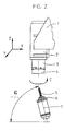
- the axis of the milling spindle 6, denoted by 7, points out Figure 2 can be seen, compared to that by the axes X and Y.
- certain plane an angle that is denoted by ⁇ and represents a solid angle, which results from that the milling spindle with respect to the workpiece 4 an angle of attack ⁇ to achieve a deviation from the circular shape Profile cross section and takes up another angle, which is necessary to a certain helix angle achieve.
- a cam disk 4 is shown in FIGS. 3 and 4, that forms the workpiece.
- On the outer circumference of this Workpiece recesses 8 are formed, by means of the machine tool according to FIGS. 1 and 2 to be manufactured.
- the X axis of the machine coordinate system forms with the X axis of the workpiece coordinate system an angle.
- the Z axes of both systems run parallel to each other. These angles between the two X-axes are in the control system of the machine tool, d. H. taken into account in the software. From this results the possibility of using surface recesses both a left slope as well as a right slope without Swiveling the milling spindle only by interpolation between the axes X, Y and Z of the machine coordinate system to reach.
- the milling spindle in your Location does not have to be changed.
Landscapes
- Engineering & Computer Science (AREA)
- Human Computer Interaction (AREA)
- Manufacturing & Machinery (AREA)
- Physics & Mathematics (AREA)
- General Physics & Mathematics (AREA)
- Automation & Control Theory (AREA)
- Mechanical Engineering (AREA)
- Numerical Control (AREA)
- Milling Processes (AREA)
Abstract
Description
- Figur 1:
- eine schematische Darstellung eines Spindelstockes mit Arbeitsspindel und Werkzeug in X-Richtung;
- Figur 2:
- eine Seitenansicht der Darstellung nach Figur 1;
- Figur 3:
- eine Draufsicht auf eine Kurvenscheibe; und
- Figur 4:
- eine Seitenansicht der Kurvenscheibe nach Figur 3.
Claims (3)
- Verfahren zur Bearbeitung von Werkstücken mit Oberflächenausnehmungen, zum Beispiel Nuten, mit von der Kreisform abweichendem Querschnitt, bei dem die Werkzeugachse zur Erzielung des gewünschten Querschnitts unter einem Anstellwinkel zur Z-Achse im kartesischen Koordinatensystem der Werkzeugmaschine eingestellt wird und zur Bearbeitung einer Oberflächenausnehmung mit einem Schrägungswinkel zwischen Werkstückachse und Längsachse der Oberflächenausnehmung eine Relativverschiebung zwischen Werkstück und Werkzeug in Richtung der Z-Achse und in Abhängigkeit von dem Schrägungswinkel auch in X-Richtung des kartesischen Koordinatensystems der Werkzeugmaschine durchgeführt wird und bei dem der Wechsel von einer Oberflächenausnehmung zur nächsten Oberflächenausnehmung mit gleichem Schrägungswinkel durch Relativverdrehung zwischen Werkstück und Werkzeug in Richtung der C-Achse erfolgt, dadurch gekennzeichnet, dass zur Bearbeitung zuerst der Anstellwinkel des Werkzeuges eingestellt wird, dass dann die kartesischen Koordinatensysteme von Werkstück und Werkzeug solange relativ zueinander verdreht werden, bis die Projektion der Werkzeugachse auf die X-Y-Ebene parallel zu einer angenommenen Hauptachse des Maschinenkoordinatensystems liegt, dass bei einem Schrägungswinkel von 0° die Oberflächenausnehmung ausschließlich durch Relativverschiebung von Werkzeug und Werkstück in Richtung der Z-Achse und bei Schrägungswinkeln von ± > 0° die Bearbeitung ausschließlich durch Relativverschiebung in allen drei Achsen des Maschinenkoordinatensystems erfolgt, und dass das Werkzeug relativ zum Werkstück für die positiven Schrägungswinkel an der einen Seite und für die negativen Schrägungswinkel an der spiegelbildlich gegenüber liegenden Seite in Eingriff gebracht wird.
- Verfahren nach Anspruch 1, dadurch gekennzeichnet, dass das Werkstück hängend mit freiem Spänefall bearbeitet wird.
- Verfahren nach Anspruch 1 oder 2, dadurch gekennzeichnet, dass die Werkzeugachse abweichend von der Horizontalen und der Vertikalen windschief zur Werkstückachse eingestellt wird.
Applications Claiming Priority (2)
| Application Number | Priority Date | Filing Date | Title |
|---|---|---|---|
| DE10208411 | 2002-02-27 | ||
| DE10208411A DE10208411B4 (de) | 2002-02-27 | 2002-02-27 | Verfahren zur Bearbeitung von Werkstücken mit geraden Oberflächenausnehmungen |
Publications (3)
| Publication Number | Publication Date |
|---|---|
| EP1341065A2 true EP1341065A2 (de) | 2003-09-03 |
| EP1341065A3 EP1341065A3 (de) | 2004-05-26 |
| EP1341065B1 EP1341065B1 (de) | 2006-03-29 |
Family
ID=27675039
Family Applications (1)
| Application Number | Title | Priority Date | Filing Date |
|---|---|---|---|
| EP03001234A Expired - Lifetime EP1341065B1 (de) | 2002-02-27 | 2003-01-20 | Verfahren zur Bearbeitung von Werkstücken mit geraden Oberflächenausnehmungen |
Country Status (6)
| Country | Link |
|---|---|
| US (1) | US6908265B2 (de) |
| EP (1) | EP1341065B1 (de) |
| JP (1) | JP4558278B2 (de) |
| KR (1) | KR20030071517A (de) |
| CN (1) | CN1440850A (de) |
| DE (2) | DE10208411B4 (de) |
Cited By (1)
| Publication number | Priority date | Publication date | Assignee | Title |
|---|---|---|---|---|
| DE102010051284A1 (de) * | 2010-11-12 | 2012-05-16 | Mag Ias Gmbh | Verfahren zum Herstellen von schrägstehenden Nuten in der Außen- oder Innenumfangsfläche eines rotationssymmetrischen Grundkörpers |
Families Citing this family (7)
| Publication number | Priority date | Publication date | Assignee | Title |
|---|---|---|---|---|
| JP2005071016A (ja) * | 2003-08-22 | 2005-03-17 | Fanuc Ltd | 数値制御装置 |
| DE102007031695A1 (de) * | 2007-07-06 | 2009-01-08 | Sandvik Intellectual Property Ab | Verfahren zum Fräsen von Kugelbahnen und Scheibenfräser für Kugelbahnen |
| CN103028784B (zh) * | 2012-11-30 | 2015-04-15 | 武汉船用机械有限责任公司 | 一种锥孔内键槽的加工方法 |
| CN103433541B (zh) * | 2013-08-05 | 2015-04-15 | 烟台海德机床有限公司 | 等分槽铣削装置 |
| CN103752925A (zh) * | 2013-12-20 | 2014-04-30 | 柳州正菱集团有限公司 | 一种汽车刹车调整臂铸件的精铣键槽工艺 |
| CN104772529B (zh) * | 2015-04-14 | 2017-07-28 | 佛山市高明永川机车配件制造有限公司 | 一种链条链锁销轴自动搓槽设备 |
| CN109500438A (zh) * | 2018-11-18 | 2019-03-22 | 湖南新融创科技有限公司 | 一种铝合金手机外壳铣槽装置 |
Family Cites Families (23)
| Publication number | Priority date | Publication date | Assignee | Title |
|---|---|---|---|---|
| US1671354A (en) * | 1926-08-10 | 1928-05-29 | Leeuw Adolph L De | Inverted unitary chucking machine |
| DE1270928B (de) * | 1961-09-21 | 1968-06-20 | Birfield Eng Ltd | Vorrichtung zum Fraesen von Rillen in Werkstuecke |
| US3782847A (en) * | 1971-12-29 | 1974-01-01 | L Kulzer | Method and apparatus for reconditioning cylinder heads |
| US4543020A (en) * | 1983-05-16 | 1985-09-24 | Usm Corporation | Method of manufacturing large gears |
| US4589174A (en) * | 1984-03-27 | 1986-05-20 | Brigham Young University | Polar coordinate apparatus |
| JPS6179508A (ja) * | 1984-09-28 | 1986-04-23 | Komatsu Ltd | 数値制御式斜面加工方法 |
| JPH0643002B2 (ja) * | 1986-02-17 | 1994-06-08 | 株式会社森精機製作所 | Nc旋盤 |
| JPS63127867A (ja) * | 1986-11-18 | 1988-05-31 | G N Tool Kk | マシニングセンタを利用したヘリカル溝加工法 |
| JPS6435606A (en) * | 1987-07-30 | 1989-02-06 | Fanuc Ltd | Nc data preparing system for grooving |
| US4981402A (en) * | 1987-08-24 | 1991-01-01 | The Gleason Works | Multi-axis bevel and hypoid gear generating machine |
| DE3735858A1 (de) * | 1987-10-23 | 1989-05-03 | Chiron Werke Gmbh | Vorrichtung zum einbringen von befestigungsbohrungen oder ventilbohrungen in eine schuessel bzw. eine felge eines rades eines kraftfahrzeuges |
| JP2726735B2 (ja) * | 1990-05-24 | 1998-03-11 | ファナック株式会社 | 円筒補間方式 |
| JPH05200601A (ja) * | 1992-01-24 | 1993-08-10 | Takizawa Tekkosho:Kk | 工作機械 |
| JPH06230817A (ja) * | 1993-01-29 | 1994-08-19 | Fanuc Ltd | 加工位置回転プログラムシフト方法 |
| DE4422416C1 (de) * | 1994-06-29 | 1996-01-11 | Magnus Dipl Ing Gruener | Bearbeitungszentrum |
| JPH0885046A (ja) * | 1994-07-13 | 1996-04-02 | Hitachi Ltd | スクロール加工方法およびその装置ならびにスクロール圧縮機 |
| DE19514058C2 (de) * | 1995-04-13 | 1998-04-30 | Emag Masch Vertriebs Serv Gmbh | Drehmaschine mit mehreren Spindeln |
| US5759140A (en) * | 1995-04-19 | 1998-06-02 | Ingersoll Cm Systems, Inc. | Method and apparatus for machining holes in crankshafts |
| DE59705215D1 (de) | 1997-12-06 | 2001-12-06 | Iprotec Masch & Edelstahlprod | Verfahren zur Fertigbearbeitung der Kugelschale eines Gleichlaufgelenkes |
| DE29807842U1 (de) * | 1998-04-30 | 1998-07-30 | Emag-Maschinen Vertriebs- und Service GmbH, 73084 Salach | Bearbeitungsvorrichtung für die Bearbeitung bereits gehärteter Werkstücke |
| JP2959559B1 (ja) * | 1998-07-01 | 1999-10-06 | 住友電気工業株式会社 | 正面フライスカッタのクランプ機構 |
| DE19847378A1 (de) * | 1998-10-14 | 2000-04-27 | Zerbst Gmbh Werkzeugmasch | Bearbeitungsvorrichtung für Werkstücke |
| JP2001277235A (ja) * | 2000-04-04 | 2001-10-09 | Mitsubishi Materials Corp | コーナー溝加工方法及び加工装置 |
-
2002
- 2002-02-27 DE DE10208411A patent/DE10208411B4/de not_active Expired - Fee Related
-
2003
- 2003-01-20 EP EP03001234A patent/EP1341065B1/de not_active Expired - Lifetime
- 2003-01-20 DE DE50302777T patent/DE50302777D1/de not_active Expired - Lifetime
- 2003-02-21 JP JP2003044127A patent/JP4558278B2/ja not_active Expired - Lifetime
- 2003-02-26 CN CN03106398A patent/CN1440850A/zh active Pending
- 2003-02-26 KR KR10-2003-0011869A patent/KR20030071517A/ko not_active Withdrawn
- 2003-02-27 US US10/376,050 patent/US6908265B2/en not_active Expired - Lifetime
Cited By (3)
| Publication number | Priority date | Publication date | Assignee | Title |
|---|---|---|---|---|
| DE102010051284A1 (de) * | 2010-11-12 | 2012-05-16 | Mag Ias Gmbh | Verfahren zum Herstellen von schrägstehenden Nuten in der Außen- oder Innenumfangsfläche eines rotationssymmetrischen Grundkörpers |
| EP2452770A3 (de) * | 2010-11-12 | 2014-05-14 | MAG IAS GmbH | Verfahren zum Herstellen von schrägstehenden Nuten in der Außen- oder Innenumfangsfläche eines rotationssymmetrischen Grundkörpers |
| DE102010051284B4 (de) * | 2010-11-12 | 2014-11-20 | Mag Ias Gmbh | Verfahren und Werkzeugmaschine zum Herstellen von schrägstehenden Nuten in der Außen- oder Innenumfangsfläche eines rotationssymmetrischen Grundkörpers |
Also Published As
| Publication number | Publication date |
|---|---|
| DE50302777D1 (de) | 2006-05-18 |
| US20030161698A1 (en) | 2003-08-28 |
| CN1440850A (zh) | 2003-09-10 |
| EP1341065B1 (de) | 2006-03-29 |
| EP1341065A3 (de) | 2004-05-26 |
| KR20030071517A (ko) | 2003-09-03 |
| DE10208411B4 (de) | 2004-11-04 |
| US6908265B2 (en) | 2005-06-21 |
| JP4558278B2 (ja) | 2010-10-06 |
| DE10208411A1 (de) | 2003-09-11 |
| JP2004001180A (ja) | 2004-01-08 |
Similar Documents
| Publication | Publication Date | Title |
|---|---|---|
| DE69417882T2 (de) | Werkzeugeinstechverfahren für zahnradherstellverfahren | |
| EP2338640B1 (de) | Maschine zur Bearbeitung von optischen Werkstücken, insbesondere von Kunststoff-Brillengläsern | |
| EP1590712B1 (de) | Verfahren zur steuerung von relativbewegungen eines werkzeuges gegen ein werkstück | |
| EP0467892B1 (de) | Verfahren zur formgebenden bearbeitung von werkstücken | |
| EP1910003B1 (de) | Universalmaschine zur weichbearbeitung von kegelrädern und entsprechendes verfahren | |
| EP0665076B1 (de) | Verfahren zum Feinbearbeiten von Zahnrädern und dafür geeignetes innenverzahntes Werkzeug sowie Verfahren zum Abrichten dieses Werkzeugs und dafür geeignetes Abrichtrad | |
| EP2923790B1 (de) | Verfahren zum schleifenden Bearbeiten von Kegelrädern im Einzelteilverfahren | |
| EP2221693A2 (de) | Verfahren und Vorrichtung zum Erzeugen von Steuerdaten zum Steuern eines Werkzeugs an einer zumindest 5 Achsen umfassenden Werkzeugmaschine | |
| DE3519402A1 (de) | Nc-vertikalschleifmaschine | |
| EP1118428B2 (de) | Drehmaschine | |
| DE102015112577A1 (de) | Werkzeugmaschine | |
| DE102016102651A1 (de) | Vorrichtung und Verfahren zur spanenden Bearbeitung eines rotierenden Werkstücks | |
| EP3959028B1 (de) | Verfahren und vorrichtung zum herstellen von verzahnten werkstücken, insbesondere schiebemuffen, sowie werkzeug dafür | |
| EP3349934A1 (de) | Verfahren und vorrichtung zum herstellen und entgraten von verzahnungen | |
| DE102015012908B3 (de) | Verfahren und Vorrichtung zum Herstellen und Entgraten von Verzahnungen | |
| DE102007033767B4 (de) | Verfahren und Vorrichtung zur Bearbeitung von Werkstückoberflächen | |
| EP3999273A1 (de) | Werkzeugmaschine und verfahren für die wälzbearbeitung von rotationsteilen mit nutförmigen profilen | |
| DE102011119000A1 (de) | Verzahnmaschine und Verfahren zur Herstellung oder Bearbeitung von Verzahnungen | |
| DE102013003769A1 (de) | Verzahnmaschine | |
| EP1341065B1 (de) | Verfahren zur Bearbeitung von Werkstücken mit geraden Oberflächenausnehmungen | |
| DE102009039346A1 (de) | Verfahren zur spanenden Drehbearbeitung und Drehbearbeitungsvorrichtung | |
| CH697397B1 (de) | Verfahren und Vorrichtung zum Schleifen eines Profils eines Werkstücks. | |
| DE102015012190B3 (de) | Wälzfräsmaschine zum Herstellen und Entgraten von Verzahnungen | |
| EP3246125B1 (de) | Werkzeugschwenkaggregat für eine drehmaschine | |
| DE69222871T2 (de) | Verfahren zum ausrichten und zur winkeleinstellung von fräserschneiden mittels schärfen |
Legal Events
| Date | Code | Title | Description |
|---|---|---|---|
| PUAI | Public reference made under article 153(3) epc to a published international application that has entered the european phase |
Free format text: ORIGINAL CODE: 0009012 |
|
| AK | Designated contracting states |
Kind code of ref document: A2 Designated state(s): AT BE BG CH CY CZ DE DK EE ES FI FR GB GR HU IE IT LI LU MC NL PT SE SI SK TR |
|
| AX | Request for extension of the european patent |
Extension state: AL LT LV MK RO |
|
| PUAL | Search report despatched |
Free format text: ORIGINAL CODE: 0009013 |
|
| AK | Designated contracting states |
Kind code of ref document: A3 Designated state(s): AT BE BG CH CY CZ DE DK EE ES FI FR GB GR HU IE IT LI LU MC NL PT SE SI SK TR |
|
| AX | Request for extension of the european patent |
Extension state: AL LT LV MK RO |
|
| 17P | Request for examination filed |
Effective date: 20040426 |
|
| AKX | Designation fees paid |
Designated state(s): DE FR IT |
|
| GRAP | Despatch of communication of intention to grant a patent |
Free format text: ORIGINAL CODE: EPIDOSNIGR1 |
|
| GRAS | Grant fee paid |
Free format text: ORIGINAL CODE: EPIDOSNIGR3 |
|
| GRAA | (expected) grant |
Free format text: ORIGINAL CODE: 0009210 |
|
| AK | Designated contracting states |
Kind code of ref document: B1 Designated state(s): DE FR IT |
|
| PG25 | Lapsed in a contracting state [announced via postgrant information from national office to epo] |
Ref country code: IT Free format text: LAPSE BECAUSE OF FAILURE TO SUBMIT A TRANSLATION OF THE DESCRIPTION OR TO PAY THE FEE WITHIN THE PRESCRIBED TIME-LIMIT;WARNING: LAPSES OF ITALIAN PATENTS WITH EFFECTIVE DATE BEFORE 2007 MAY HAVE OCCURRED AT ANY TIME BEFORE 2007. THE CORRECT EFFECTIVE DATE MAY BE DIFFERENT FROM THE ONE RECORDED. Effective date: 20060329 |
|
| REF | Corresponds to: |
Ref document number: 50302777 Country of ref document: DE Date of ref document: 20060518 Kind code of ref document: P |
|
| ET | Fr: translation filed | ||
| PLBE | No opposition filed within time limit |
Free format text: ORIGINAL CODE: 0009261 |
|
| STAA | Information on the status of an ep patent application or granted ep patent |
Free format text: STATUS: NO OPPOSITION FILED WITHIN TIME LIMIT |
|
| 26N | No opposition filed |
Effective date: 20070102 |
|
| REG | Reference to a national code |
Ref country code: FR Ref legal event code: PLFP Year of fee payment: 14 |
|
| REG | Reference to a national code |
Ref country code: FR Ref legal event code: PLFP Year of fee payment: 15 |
|
| REG | Reference to a national code |
Ref country code: FR Ref legal event code: PLFP Year of fee payment: 16 |
|
| PGFP | Annual fee paid to national office [announced via postgrant information from national office to epo] |
Ref country code: IT Payment date: 20210129 Year of fee payment: 19 Ref country code: FR Payment date: 20210126 Year of fee payment: 19 |
|
| PGFP | Annual fee paid to national office [announced via postgrant information from national office to epo] |
Ref country code: DE Payment date: 20210127 Year of fee payment: 19 |
|
| REG | Reference to a national code |
Ref country code: DE Ref legal event code: R119 Ref document number: 50302777 Country of ref document: DE |
|
| PG25 | Lapsed in a contracting state [announced via postgrant information from national office to epo] |
Ref country code: DE Free format text: LAPSE BECAUSE OF NON-PAYMENT OF DUE FEES Effective date: 20220802 |
|
| PG25 | Lapsed in a contracting state [announced via postgrant information from national office to epo] |
Ref country code: FR Free format text: LAPSE BECAUSE OF NON-PAYMENT OF DUE FEES Effective date: 20220131 |
|
| PG25 | Lapsed in a contracting state [announced via postgrant information from national office to epo] |
Ref country code: IT Free format text: LAPSE BECAUSE OF NON-PAYMENT OF DUE FEES Effective date: 20220120 |