EP1341082A2 - Méthode pour la génération assistée par ordinateur d'une interface graphique d'utilisateur d'une unité de monitorisation ou de contrôle d'un appareil - Google Patents
Méthode pour la génération assistée par ordinateur d'une interface graphique d'utilisateur d'une unité de monitorisation ou de contrôle d'un appareil Download PDFInfo
- Publication number
- EP1341082A2 EP1341082A2 EP03003279A EP03003279A EP1341082A2 EP 1341082 A2 EP1341082 A2 EP 1341082A2 EP 03003279 A EP03003279 A EP 03003279A EP 03003279 A EP03003279 A EP 03003279A EP 1341082 A2 EP1341082 A2 EP 1341082A2
- Authority
- EP
- European Patent Office
- Prior art keywords
- user interface
- building
- basic structure
- detailed data
- controlled
- Prior art date
- Legal status (The legal status is an assumption and is not a legal conclusion. Google has not performed a legal analysis and makes no representation as to the accuracy of the status listed.)
- Ceased
Links
Images







Classifications
-
- G—PHYSICS
- G06—COMPUTING OR CALCULATING; COUNTING
- G06F—ELECTRIC DIGITAL DATA PROCESSING
- G06F8/00—Arrangements for software engineering
- G06F8/30—Creation or generation of source code
- G06F8/34—Graphical or visual programming
-
- G—PHYSICS
- G06—COMPUTING OR CALCULATING; COUNTING
- G06F—ELECTRIC DIGITAL DATA PROCESSING
- G06F8/00—Arrangements for software engineering
- G06F8/30—Creation or generation of source code
- G06F8/38—Creation or generation of source code for implementing user interfaces
-
- H—ELECTRICITY
- H04—ELECTRIC COMMUNICATION TECHNIQUE
- H04L—TRANSMISSION OF DIGITAL INFORMATION, e.g. TELEGRAPHIC COMMUNICATION
- H04L12/00—Data switching networks
- H04L12/28—Data switching networks characterised by path configuration, e.g. LAN [Local Area Networks] or WAN [Wide Area Networks]
- H04L12/2803—Home automation networks
- H04L12/2805—Home Audio Video Interoperability [HAVI] networks
-
- H—ELECTRICITY
- H04—ELECTRIC COMMUNICATION TECHNIQUE
- H04L—TRANSMISSION OF DIGITAL INFORMATION, e.g. TELEGRAPHIC COMMUNICATION
- H04L12/00—Data switching networks
- H04L12/28—Data switching networks characterised by path configuration, e.g. LAN [Local Area Networks] or WAN [Wide Area Networks]
- H04L12/2803—Home automation networks
- H04L12/2816—Controlling appliance services of a home automation network by calling their functionalities
- H04L12/282—Controlling appliance services of a home automation network by calling their functionalities based on user interaction within the home
Definitions
- the invention relates to a method for generating a graphical user interface and a device monitoring / control unit.
- HTML format H yper t ext M arkup L anguage
- WML format W ireless M arkup L anguage
- the invention is based on the problem of a method for computer-aided Generate a graphical user interface of a device monitoring unit and / or device control unit and a device monitoring / control unit specify with which or with a very simple monitoring and / or control a variety of devices easily using standard browser technology is made possible.
- a graphic User interface of a device monitoring unit and / or device control unit becomes a basic structure of the graphical on a basic configuration file UI determined.
- the basic structure ie the structure of a graphical user interface, preferably defined in accordance with the HTML format or the WML format, is stored in the basic configuration file.
- the base structure itself is coded configuration file base, preferably according to a meta data format, for example, in accordance with the XML format (E xtended M arkup L anguage).
- the basic structure contains information in particular as parameters, via which devices more detailed data in the graphical user interface in the graphical user interface recorded and displayed to a user should.
- the desired and specified device-specific static detailed data a device-specific device configuration file, which is usually provided by a Reference in the basic structure itself in the form of a pointer (clearly a path specification), preferably a URL.
- a device-specific device configuration file which is usually provided by a Reference in the basic structure itself in the form of a pointer (clearly a path specification), preferably a URL.
- the basic structure also contains information about which Devices each state information, generally any kind of changing, than dynamic information, hereinafter also referred to as dynamic detail data, be desired.
- the specified dynamic detail data which are from a are to be provided in each case to be monitored and / or controlled and which each have a current status of the to be monitored and / or the controlling device are determined.
- current in such a way that the state is determined in each case the device last provided as status information.
- the graphical user interface is generated according to the Basic structure, the static detailed data and the dynamic detailed data, where usually the static detailed data and the dynamic detailed data in the graphical user interface according to the basic structure.
- a monitoring / control unit has a processor unit for generating one graphical user interface, the processor unit being set up in such a way that the process steps described above can be carried out.
- the invention makes it possible in a very simple manner for a large number different devices a graphical user interface for monitoring and / or to control the different devices, the graphical User interface is formed from a general basic structure as well as the general one Basic structure of the device-specific, detailed static data, which can be accessed via the Time are unchangeable, but depend on the respective devices, whereby the static detailed data each in different, specific for the devices Device configuration files are included, which ensures that a Extension of the respective devices to be monitored or controlled by simply expand or add or remove a respective one device-specific device configuration file is enabled.
- Monitoring and / or control are also becoming more continuous State changes of the devices by taking into account the dynamic detailed data reached via a device to be monitored or controlled.
- the determination of the base structure and / or the static detail data and / or dynamic detail data is according to an embodiment of the invention according to a communication protocol of the application layer in the sense of the OSI reference model (O pen S ystem I nterconnection reference model).
- a communication protocol of the application layer in the sense of the OSI reference model (O pen S ystem I nterconnection reference model).
- the communication protocol in accordance with the HTTP standard (H yper t ext T ransport P rotocol) or the WAP standard (W ireless A pplication P rotocol) as the communication protocol of the application layer.
- the basic structure in a respective basic configuration file is according to a Design of an invention according to a metadata format, further preferably encoded according to XML format.
- the basic configuration file and / or the device configuration file can be in one Memory of a building gateway computing device, hereinafter also as a residential Gateway designated, be saved.
- the base structure is determined by the Control unit sends a basic structure request message to the building gateway computing device transmitted and based on the basic structure request message the desired basic structure is determined from the basic structure configuration file and it becomes a basic structure message from the building gateway computing device formed, which contains the requested basic structure.
- the base structure message formed is from the building gateway computing device transmitted to the control unit.
- a first one can be determined by the control unit in order to determine the static detailed data Detail data request message to the building gateway computing device are transmitted, whereupon the building gateway computing device desired first static detailed data from the respective device-specific device configuration files determined.
- the building gateway computing device then generates a first Generated detail data message, which contains the requested static detailed data.
- the first detailed data message is sent from the building gateway computing device to the Control unit transmitted.
- a control unit is also used to determine the dynamic detailed data second detailed data request message to the building gateway computing device transmitted, in which, according to the basic structure, contain second detailed data are.
- the building gateway computing device After receiving the second detail data request message, the building gateway computing device the respective status is determined for the respective device, i.e. the requested dynamic detailed data are read out and / or by the each device itself. Once the second detailed data has been determined, a second detailed data message containing this from the building gateway computing device formed and transmitted by this to the control unit.
- the basic structure request message, the first detailed data request message and the second detail data request message can be in a request message or be summarized in two request messages, in which the respective requested data can be requested.
- the data of the basic structure, the first detailed data and / or the second detailed data in a memory of the building gateway computing device themselves can be saved.
- the data from one or several other (server) computers or devices can be determined and after determination made by the building gateway computing device to the Control unit can be transmitted in the manner described above.
- the device to be monitored and / or controlled can be any communicable in a building and with a corresponding Be coupled device in the home bus system, preferably the device is a communication-capable household appliance.
- the second detailed data in this case from the domestic appliance to the device monitoring / control unit and / or to one Building gateway computing device according to an in-house communication protocol, if the device is a home appliance, according to a home appliance communication protocol transmitted.
- EHS communication protocol E uropean H OMe S ystems communication protocol
- HES communication protocol H ome E lectronic S ystem
- FIG. 1 shows a control system 100 with a large number of buildings 101, 102, 103, a public telecommunications network 104, an administration server computer 105 and external control units 106, 107, 108, 109.
- each building gateway computing device 110, 111, 112 a memory 113, 114, 115 and has a processor 116, 117, 118.
- At least one first communication interface (not shown) provided, which is set up for communication of the building gateway computing device 110, 111, 112 with one or more in the respective building arranged devices to be controlled 119, 120, 121, 122, 123, 124, 125, 126, 127, 128, 129, 130, which via respective communication connections 131, 132, 133, 134, 135, 136, 137, 138, 139, 140, 141, 142 with the respective building gateway computing device 110, 111, 112 are coupled, the devices to be controlled 119, 120, 121, 122 in the first building 101, the devices to be controlled 123, 124, 125 in the second building 102 and the devices to be controlled 126, 127, 128, 129, 130 in the third building 103 are arranged.
- the communication connections can 131, 132, 133, 134, 135, 136, 137, 138, 139, 140, 141, 142 using different transmission principles and thus also on using different communication protocols and communication media , which is usually several different first Communication interfaces in the respective building gateway computing device 110, 111, 112 are provided.
- each building gateway computing device 110, 111, 112 There is also a second communication interface in each building gateway computing device 110, 111, 112 provided, via which second Communication interface the building gateway computing device 110, 111, 112 is coupled to the public communication network 104.
- the communication via the public communication network 104 is performed using the T ransport C ontrol P rotocols (TCP) and the I nternet P rotocols (IP).
- TCP T ransport C ontrol P rotocols
- IP I nternet P rotocols
- the building gateway computing devices 110, 111, 112 are each second Communication links 143, 144, 145 with the public Telecommunications network 104 connected.
- the respective building gateway computing device 110, 111, 112 managing server computer 105 via a third communication link 146 coupled to the public communication network 104 and above with the respective Building gateway computing device 110, 111, 112.
- the external control units 106, 107, 108, 109 which are used to control the controlling devices 119, 120, 121, 122, 123, 124, 125, 126, 127, 128, 129, 130, are via a fourth communication link 147 (external control unit 106) the public communication network 104 to the respective building gateway computing devices 110, 111, 112 coupled or immediate, without a connection to build over the public communications network, over fifth Communication links 148, 149, 150 directly to the respective building gateway computing device 110, 111, 112, whereby in this case the communication under The communication protocols TCP and IP are used.
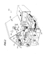
- FIG. 2 shows a sketch of a building 200 according to an exemplary embodiment of the invention.
- a building gateway computing device 201 is provided, which is designed as described in FIG . 1 .
- a characteristic of the building gateway computing device 201 is that the Management, in particular the installation and maintenance of the building gateway computing device 201 takes place via the server computer 105 and not via one User who has immediate access to the building gateway computing device 201 in the building receives 200.
- the personal computer 202 is connected to the building gateway computing device 201 coupled with the Internet, in other words, the first communication interface to Communication between the building gateway computing device 201 and the Personal computer 202 is set up for communication in accordance with the Internet Protocol.
- the garage door opener 203 is connected to the building gateway computing device 201 a Bluetooth communication link coupled, in other words, to Communication with the garage door opener 203 is the first communication interface designed according to the Bluetooth protocol and communication takes place via a Air interface.
- the digital camera 204 and the motion detector 205 are with the building gateway computing device 201 via a first designed as a USB interface Communication interface with the building gateway computing device 201 coupled and controllable by the USB communication protocol.
- the stereo system 206 and the video recorder 218 and the television 219 are with the Building gateway computing device 201 via one according to the HAVi standard established communication interface coupled and above that of the building gateway computing device 201 controllable.
- the lights 207, 208, 209 as well as the blind control 210 and the heating system 211 are connected to the building gateway computing device 201 via an according to the EIB / LonWorks communication protocol coupled and in accordance with this protocol from this controllable.
- the household appliances in particular the washing machine 212, and the Kitchen appliances, that is, the microwave 213, the refrigerator 214, the refrigerator 215, cooker 216 and dishwasher 217 are with the building gateway computing device 201 via a first set up according to the EHS standard Communication interface coupled and by this according to the EHS communication protocol controllable.
- FIG. 2 An external, preferably central, control unit 220 is also shown in FIG. 2 , which is used to control the devices 202, 203, 204, 205, 206, 207, 208, 209, 210, 211, 212, 213, 214 to be controlled , 215, 216, 217, 218, 219.
- the external control unit 220 is on via a direct communication link physical level set up according to the DECT standard, at the level of Transport layers using TCP and IP over one to communicate in this form of a second communication interface in the building gateway computing device 201 coupled with this.
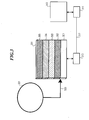
- FIG 3 shows the design of the building gateway computing device 201 according to the exemplary embodiment of the invention.
- FIG. 3 the design is symbolically indicated in the form of a block diagram.
- Hardware 301 is provided in the building gateway computing device 201, which a communication via a first Powerline modem 310, which to the Hardware 301, in particular to an input-output interface of hardware 301 is connected.
- any operating system can be used according to the invention, which the each platform-independent execution layer used is supported.
- a Java Virtual Machine 303 is platform-independent Execution layer computer program installed on which Java Virtual Machine one object-oriented service platform, an OSGI framework according to this exemplary embodiment 304, clearly a basic class system, installed.
- C # can be used as the execution layer, in which case UPnP as Communication protocol can be used.
- the building gateway computing device 201 is via the first powerline modem 310 with a second Powerline modem 311 via a power line as a Powerline communication link 312 coupled. With the second Powerline Modem 311 the respective device 313 to be controlled is coupled.
- Communication takes place via the powerline communication link 312 the building gateway computing device 201 and the device 313 to be controlled according to the EHS communication protocol.
- the powerline communication link 312 thus provides the local building network represents.
- server computer 321 coupled to the building gateway computer device 201 via the public communication network 320 is shown symbolically in FIG .
- a wide variety of principles and therefore can be used for physical data transmission different media using the public communication network 320 are used, for example an ISDN communication network, an ADSL communication network, a common analog telecommunications network, etc.
- FIG. 4 shows a more detailed illustration of the OSGI bundles 305 provided according to the invention.
- a bundle is generally to be understood as an object, the service interfaces and contains their implementations and other resources, for example HTML pages or pictures.
- a bundle clearly provides a functional component when it is is installed and activated within the respective service platform.
- Bundle a service or function ready, for example to control one controlling device or a service, preferably a higher quality service in the Framework of the OSI reference model, for example an application layer service, a service that communicates according to the respective protocol enables the application layer.
- a EHS driver bundle 401 As bundles in accordance with 305, a EHS driver bundle 401, a Java driver bundle 402, device-specific bundle 403, 404, 405, 406, bundles 407 for providing communication application layer protocols such as HTTP (H yper t ext T ransfer P rotocol), WAP ( W ireless A pplication P rotocol), mPRM.
- a GUI bundle 408 is also provided, which provides the services of the GUI layer described below. The services described below are made available as part of the gateway portal by means of a portal bundle 409 which is also provided.
- an SMS-bundle 410 which includes a short message service (S hort M essage S ervice SMS) service provides as well as a WAP-bundle 411, which allows communication mechanisms to communicate according to the WAP protocol.
- SMS short message service
- WAP-bundle 411 which allows communication mechanisms to communicate according to the WAP protocol.
- the bundles 401, 402, 403, 404, 405, 406, 407, 408, 409, 410 are each such set up that they the respective function described below, that is, the have implemented the respective service and thus provide it.
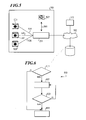
- the building gateway computing device 201 is connected to the devices 501 to be controlled, 502, 503 via communication links 504, 505, 506, according to this Embodiment via a powerline communication link and an EHS communication protocol controlling coupled.
- Devices 501, 502, 503 are according to this embodiment washing machines.
- the external control unit 507 according to FIG. 5 is coupled directly to the building gateway computer device 201 via an Internet / intranet communication connection 508, the term “direct” being understood such that the communication connection 508 is not established via the public communication network 509 via which public communication network 509 a server computer 510 is coupled to the building gateway computing device 201 in order to manage it.
- the devices to be controlled are using the EHS communication protocol via a Powerline communication interface with the Building gateway computing device 201 coupled.
- the building address is determined by the device that is sent to the local device first Building network is connected, generated and is connected to all other devices be connected to the local building network at a later time, distributed.
- the building gateway computing device 201 tries to control the building address by one at the time when the building gateway computing device 201 is connected to the control system Get device in building 200 (step 601).
- Step 602 in the event that the building gateway computing device 201 no building address from another EHS capable receives device to be controlled, generates a new building address (step 602) and it is then checked whether this newly generated building address already exists (Step 603).
- step 602 a branch is made in step 602 and a new building address is created generated and in turn checked whether this then generated building address also already exists. This loop continues until the building gateway computing device 201 a building address has been generated that has not yet exist.
- the building address generated is assigned to the device and saved (step 604).
- step 601 If a building address is already obtained in the first step (step 601), then branches immediately in step 604 and the building address obtained is sent to the device assigned and saved.
- the building gateway computing device 201 After the building gateway computing device 201 has a building address in itself has determined itself, it detects those devices that are already connected to the system, that is in other words, connected to the local building network.
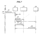
- This process is shown in more detail in the message flow diagram 700 in FIG . 7 .
- a user 701 contacts the building gateway computing device 201 via an external control unit, which step is shown in FIG . 7 with a contacting message 702.
- the building gateway computing device 201 generates its own building address for the external control unit (step 703) and then sends a request message 704 to all devices 705, 706 connected to the local building network, which in response to the Request message 704 send a response message 707, 708 back to the building gateway computing device 201, with which response message 707, 708 the devices 705, 706 indicate their presence within the control system.
- a new device to be controlled is connected to the local building network and, via this, to the building gateway computing device 201, a separate building address is assigned to the respective new device in accordance with the method shown in FIG .
- the building gateway computing device 201 is switched by the user 701 into a building address distribution mode, in which mode the device to be newly installed receives a new and unique building address from the building gateway computing device 201 for this device can.
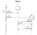
- FIG. 8 shows in a message flow diagram 800 the procedure in which the user 701 uses a building address distribution message 801 to the building gateway computing device 201 to switch to the building address distribution mode in which the building gateway computing device 201 does its own Sends the building address for a predetermined period of time to all devices connected to the local building network via the local building network.
- the user 701 After sending out the building address, the user 701 connects the device to the local building network and a registration message 802 is sent from the external control unit to the new device 803 to be controlled, whereupon the new device 803 to be controlled sends a building address request message 804 to the building Gateway computer device 201 sends, which generates a new building address for the new device 803 to be controlled in accordance with the method shown in FIG . 6 and transmits the newly generated building address in a building address message 805 to the device 803 to be controlled. Subsequently, the device 803 to be controlled sends a response message 806 to the building gateway computing device 201 upon receipt of a building address, by means of which the presence of the device 803 in the control system is indicated.
- the building gateway computing device 201 After the building addresses in the control system and to the local Building network connected devices to be controlled have been assigned, and all devices to be controlled are detected by the building gateway computing device 201 the building gateway computing device 201 registers with the connected devices to be controlled in order to access the respective functions of the Get devices.
- the building gateway computing device 201 Based on the information read in above, the building gateway computing device 201 a suitable device driver set up as device specific OSGI bundle selected (step 902). This selection is made according to the known mechanism defined in the OSGI standard.
- step 903 If no suitable device driver as an OSGI bundle in the memory of the building gateway computing device 201 has been found (step 903), then one Download request message 904 transmitted to the server computer 105 and a suitable device-specific driver bundle is in a reply message 905 from the Server computer 105 transmitted to the building gateway computing device 201 and saved there.
- Command 1001 to start a washing machine is transmitted by the building gateway computing device 201 a command message 1002 to the first powerline modem 310 sent and from this to the second Powerline modem (not shown) forwarded, via which the command message 1002 to the device 311 to be controlled is fed.
- the Command message 1002 from the first powerline modem 310 of the building gateway computing device 201 confirms that the command message to the second Powerline modem, which is assigned to the respective device 803 to be controlled without collision the data transmission has been transmitted.
- each of them can controlling device 311 on the user interface of the external control unit, which according to the exemplary embodiment using an HTTP browser client program is configured, data generated by the device 311 to be controlled to be provided.
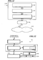
- 11 shows the logical structure of the computer program elements implemented in the building gateway computing device 201 in the form of a communication layer model 1100.
- EHS layer 1101 higher level that is to say the services of the EHS layer 1101 Device driver layer 1102 and above, the services of the device driver layer 1102 claiming GUI layer (graphical user interface layer) 1,103th
- a Trialog EHS modem 1104 becomes the first powerline modem via the EHS layer 1101 310 controlled, which is coupled to the powerline communication network 1105 is what a powerline communication link with the second powerline modem is about 311 can be built.
- the EHS communication component 1202 is also via a serial interface, according to this embodiment via an RS232 interface with the first Powerline modem 1104 coupled and above and via the Powerline communication network 1204 as a local building network with the also to the Powerline communication network 1204 connected devices to be controlled 1205, 1206.
- 1206 such as a refrigerator or a washing machine is a device driver bundle - also called Device driver bundle computer program called - provided and this assigned.
- Such a device driver bundle can clearly be seen as a virtual software device be considered.
- the building gateway computing device 201 To send messages from the building gateway computing device 201 to the first Powerline modem 1104, that is, according to the exemplary embodiment, to the EHS modem 1104 to send or receive messages from the device driver bundle computer program Services that another OSGI bundle provides namely an EHS communication bundle, which is the EHS communication component 1202 implemented.
- the device driver bundle 1201 thus provides one for each specific functionalities available for each device to be controlled.
- the respective device driver bundle uses an interface for communication Application layer for the EHS communication component, which is an EHS communication bundle is realized.
- the EHS communication bundle 1202 is coupled to the EHS modem 1104.
- the format of the EHS communication protocol used is determined by the EHS communication bundle 1202 converted to the EHS application layer format and about it in the services provided by the EHS application layer.
- the services provided are thus provided by the EHS communication bundle 1202 on the EHS modem used in each case, in the format according to the exemplary embodiment, which is used by the intended Trialog EHS modem 1104, converted. In other words, this is through the EHS communication bundle 1202 implemented by the Trialog EHS modem 1104 communication protocol.
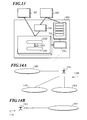
- Fig. 13 shows the structure of the EHS communication bundle 1202 in detail.
- the EHS communication bundle 1202 receives from the device driver bundle 1201 the messages to be controlled in a send queue 1301 and reads the information to be sent from this byte by byte. Using a byte to frame converter 1302, the individual bytes are in a data packet, further also referred to as a frame, merged. The frames 1303 formed are in one Frame-to-EHS command converter 1304 is actually from the EHS communication bundle 1202 EHS command sent to the device to be controlled via the RS232 interface converted.
- the RS232 interface is bidirectional, i.e. the EHS communication bundle 1202 also receives messages from the EHS modem over the RS232 interface 1104 and stores this received data in a receive queue 1305.
- An event detection mechanism 1306 is used in the Receive queue 1305 messages stored, for example in the devices Event messages that have occurred are read out and processed.
- an interface-specific one can be used instead of the Javax.comm bundle 1307 Bundle, which provides the corresponding services required Communication via a corresponding external interface, preferably a bit serial interface or a bit parallel interface, clearly the required one Interface driver functionality.
- the EHS control component 1203 dynamically assigns a building address to the device to be controlled.
- the EHS control component 1203 becomes an OSGI device management unit contacted to get the required device driver bundle computer programs to request and install.
- the EHS control bundle contains the EHS control component 1203 forms a basic driver 1207, which is a simple EHS device driver represents, by means of which reading a device identification information is possible and with which it is also possible to determine the required device driver bundle to initiate.
- the EHS control bundle 1203 is independent of the EHS modem used, generally of the particular one used modem or the actually used communication protocols and Transmission method on the physical layer on the local side Building network.
- the basic driver is therefore a component in the EHS control bundle 1203 is included.
- the EHS control component determines using the identification information 1203 the suitable device driver bundle 1201, and determines this from, if necessary the server computer.
- the base driver is used to control the device to be controlled in the building gateway computer device 201 registered.
- From the EHS control bundle 1203 are from the EHS communication bundle 1202 sent events received and to this are commands for forwarding sent to the EHS modem 1104.
- the events received by EHS Control Bundle 1203 are Registration events that are generated when a new device to be controlled is added to the local building network, according to this embodiment to the EHS network is connected.
- EHS Control Bundle 1203 If such an event is received by EHS Control Bundle 1203, the base driver will be notified of this and it will be the ones described above Actions performed by the base driver.
- the device driver bundle 1201 uses the EHS communication bundle 1202 for Communication with the hardware in the local building network.
- the EHS communication bundle 1202 is used, to send a communication protocol dependent message to the device to be controlled send.
- the device driver bundle 1201 can be found in the EHS control component Have 1203 registered so that specified events from the EHS control component forwarded to device driver component 1201, For example, status information from the device to be controlled to the building gateway computing device 201 and thus to the EHS communication component 1202 and above is sent to the EHS control bundle 1203.
- FIG. 14A and 14B show the message exchange of the EHS layer 1101 with the respective external modules, on the one hand with the device driver layer 1102, that is to say the device driver bundles 1201 (see FIG . 14A ) and with the EHS Modem 1104 on the other hand (see Fig . 14B ).
- an event that is sent from a device to be controlled to the building gateway computing device 201 is sent from the EHS modem 1104 to the EHS communication component 1203 (block 1411).
- FIG. 15 shows in a block diagram 1500 the structure of the device driver layer 1102 in detail.
- the entire control logic for controlling the contain the devices to be controlled.
- At least one device-specific device driver is in the form of device driver bundles assigned to at least part of the registered EHS device to be controlled, so that it is possible to control this.
- Device driver layer 1102 not only provides the services for discovering Information about the respective state of the device to be controlled or the execution of commands to the device to be controlled, but also the procedure for Register a device to be controlled.
- a device to be controlled or a class of devices such as a refrigerator, washing machine, etc. controlled.
- the life cycle of the devices to be controlled which is logically in the device driver layer 1102 and the life cycle of the device driver bundles themselves are registered by an OSGI device management unit 1501.
- OSGI device management unit 1501 which according to the OSGI standard devices connected to the local building network, associated device drivers and possibly a location where the required ones Find device driver bundle, i.e. saved.
- a method for implementing a device driver localization unit 1502 is implemented Determining the required and not yet in the building gateway computing device 201 device-specific device drivers included.
- a factorization registration unit 1503 is also provided.
- the factorization registration unit 1503 instantiates the required device model objects 1504, 1505, 1506, 1507, which are explained in more detail below and forms a link from the device model objects 1504, 1505, 1506, 1507 to the the respective devices and device model objects 1504, 1505, 1506, 1507 assigned device view objects, which are the mechanisms for displaying Information about the respective device on a graphical user interface provide.
- a device model object 1504, 1505, 1506, 1507 - hereinafter also referred to as a device model - as device-specific object implemented.
- the respective device functionality of the device to be controlled is implemented and the current device status is provided as status information.
- the respective device model 1504, 1505, 1506, 1507 communicates with the EHS layer 1101 and sends commands to the device to be controlled and receives from it Events.
- a universal device model can be provided as a separate object, preferably in each case at the level of a device category, for example in each case for one Washing machine, dishwasher, etc.
- the universal device model usually does not provide any device-specific functionalities ready, which would be available per a special device type.
- the device driver layer 1102 When a new device to be controlled is connected to the local building network the device driver layer 1102 generates a new device view object under Use of registered GUI factorizations, and forms a corresponding one Link to the device model 1504 assigned to the respective device view object 1505, 1506, 1507.
- device driver layer 1102 controls all devices of the same type in the EHS network as a local building network.
- the device driver layer 1102 creates device models 1504, 1505, 1506, 1507 as its own Objects that implement the device functionalities and save the current one Device status for each new controller to be connected to the local building network Device.
- a graphic User interface provided, for example according to the HTML standard or the WML standard.
- 16A to 16C describe the communication of the device driver layer 1102 with other external components.
- 16A shows in a block diagram 1600 the communication with the OSGI device management unit 1501.
- OSGI device management unit 1501 required but not yet available device drivers are determined in the building gateway computing device 201 (block 1601), it is determined whether required device drivers are already stored in the building gateway computing device 201 (block 1602) or any required device drivers are loaded by the OSGI device management unit 1501 (block 1603).
- the EHS layer 1101 transmits the EHS events transmitted from the devices to be controlled to the respectively registered objects from the devices to be controlled (block 1611) to the device driver layer 1102 using the EHS communication component 1202.
- the EHS events transmitted by the EHS layer 1101 are shown in two groups are grouped, namely in the device events (block 1612) and in the Registration events 1613.
- an EHS device event 1612 is receiving a second Confirmation message and a corresponding display message.
- the device driver layer 1102 directs this event the corresponding representation object of the GUI layer described in more detail below 1103 further.
- EHS registration events 1613 are events related to a registered one controlling device.
- Device driver layer 1102 response to an EHS registration event is the registration of a corresponding device interface from the basic driver. Then a device access mechanism is activated Identify and install a suitable device driver.
- the GUI layer 1103 and the device driver layer 1102 communicate with each other using the so-called factorization pattern, in other words under Use of the links formed between a respective device model object and the device view object assigned to it.
- Corresponding representation object for example, as an HTML device view object designated, created and registered and a corresponding device model object assigned. This is done using the GUI factoring services carried out, which are supplied with the device drivers (block 1621).
- Is the GUI layer 1103 a request to determine the status of the device to be controlled is received in the receive queue 1305 cached state value transmitted to the GUI layer 1103.
- the cached state value is obtained based on of the last device-specific event that occurred from the device to be controlled the EHS communication bundle 1202 has been sent (block 1622).
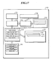
- FIG 17 shows the structure of the GUI layer 1103 in detail.
- HTTP / WAP request messages received and generated pages according to the HTML standard or the WML standard to the external control unit and above that to the Users passed.
- the request processor 1702 parses, that is, determines the requested URL address.
- Device view object 1705 activated by request processor 1702 to request a Send command to the device to be controlled or the current device Determine device status.
- Request processor 1702 also receives from the HTML / WML device view object 1705 according to the page received and generated there the HTML / WML format.
- the device list management unit 1703 provides a service by means of which all Enter device view objects automatically in device list 1704.
- the HTML / WML device view object 1705 generates the for the corresponding device requested HTML pages or WML pages for the device to be controlled.
- All widgets are stored in the form of a JS file in the widget library 1706 the respective HTTP service are registered.
- XML device configuration library 1707 are those based on XML Configuration files are saved, which are a device-specific part of the user-side Define external control unit.
- Each folder on the graphical user interface the respective external control unit, each of which has its own device to be controlled has its own configuration file 1709, 1710, 1711 assigned to it.
- the HTTP connection with the maintain the respective browser program and the respective browser program occurring events forwarded.
- the communication with the device driver layer 1102 on the one hand and a user, that is to say an external control unit on the other hand, are shown in the block diagrams 1800 in FIG. 18A and 1810 in FIG . 18B .
- a command is issued by a user using the external control unit is entered, this is to the GUI layer, which in particular the graphic Provides user interface to the external control unit, performed (block 1811).
- the respective status information of the external Control unit controlled devices which status information from the respective device driver objects is determined in the device driver layer 1102 (block 1812).
- configuration services provided, in particular the possibility according to this exemplary embodiment, use a desired language in the context of the control (block 1814), predefined short message numbers for receiving critical device events define (block 1815) and assign your own user-defined device names (Block 1816).
- device driver layer 1102 Based on a registration event, device driver layer 1102 creates instances of device view objects for each registered device to be controlled (block 1801) in FIG . 18A .
- the device driver layer 1102 notifies and removes the GUI layer 1103 the instance of the respective device view object (block 1802).
- the GUI layer 1103 of each event for the specific device to be controlled which via the GUI layer and managed via the external control unit, notified (block 1803).
- the following describes the procedure that is carried out when a new device to be controlled is connected to the local building network.
- the EHS basic driver is listening on the local building network Registration events from the EHS communication bundle 1202 to the Base drivers are forwarded.
- a new device to be controlled is sent to the local one
- a basic device object is instantiated and this is used by the one to be controlled Device whose 20-byte identification information is used as the object user name is used, read out.
- the base driver then registers a base device service that is provided by the OSGI device management unit 1501 is detected and there is a request for Localization of the required device driver to the Device driver localization component submitted.
- the EHS localization component determines a list of device driver identification information from device drivers with which the respective device is controlled and transmits this list to the basic driver. The most suitable Device driver is selected from the list.
- the EHS localization component receives the location, that is the path to the Memory or the server that provides the respective device driver. Is a If the desired device driver is not available, the universal device driver is installed. However, the desired device driver is already as a device driver bundle in the building gateway computing device 201 installed, the device driver will not be again loaded, but the device driver already saved is used.
- a device-specific for the device to be controlled Device model object generated, which registers in the EHS layer 1101, so that the object receives predefined events from the device to be controlled, when the EHS layer receives such events.
- a command message 1901 from the external control unit to the HTML / WML control servlet 1701.
- the Command message 1901 encoded according to the HTML format, with which, for example, a to controlling device is to be switched on by the HTML / WML control servlet 1701 received and from this request objects and response objects 1902 to the request processor 1702, which sends out the respective URL addresses the received query objects and response objects determined (block 1903).
- the request processor 1702 uses one Device view object request message 1904 transmitted to device list object 1704 and from this a pointer to the corresponding device view object 1905 is sent to the Request processor 1702 transmitted.
- the request object or the response object 1902 is in another Message 1906 from the request processor 1702 via the respective HTML / WML device view object 1705, which forms the respective command and a command message 1907 to the device view controller 1908.
- the request processor 1702 an HTML page request message 1909 to device view object 1705 is sent and the HTML page transmitted from there is sent to the HTML / WML control servlet 1701 transmitted as an HTML page message 1910, which to the external Control unit as page information message 1911 is transmitted.
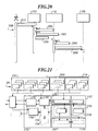
- FIG. 20 shows the sequence of an event transmitted by the EHS modem until it is transmitted to the GUI layer 1103.
- EHS event sent to the EHS modem over the local building network and this sends the EHS event as an EHS event message 2001 to the EHS communication bundle 1202, which converts the 1-byte message into a
- Frame is converted (block 2002) and the frame formed is then converted into an EHS event 2003 converted. Then an event notification message 2004 to the device model object of the device driver layer 1102 of the corresponding device to be controlled, which has sent the status change to the EHS modem, transmitted, which then updates the device status information (block 2005).
- the updated one Status information When requested by the external control unit, the updated one Status information to the device view object 1705 in a status message 2006 transfer.
- Fig. 21 summarizes the physical structure of the corresponding components in the building gateway computing device 201.
- FIG. 22 shows, in a message flow diagram 2200, a method for generating a graphic screen surface 2204 in the external control unit 2201 according to the exemplary embodiment of the invention.
- the external control unit 2201 If the external control unit 2201 is switched on, it sends one Base structure request message 2202 to the building gateway computing device 2,203th
- the control unit 2201 requests the basic structure request message 2202 Transmission of a basic structure in which the page structure of the graphic User interface 2204 is specified in the control unit 2201. According to this Embodiment of the invention is used for coding the pages of the graphic User interface 2204 uses the HTML format.
- placeholders become determined, for the static detailed data, i.e. Data that cannot be changed over time but are device specific, i.e. are specific to the device to be controlled, for which information is indicated on the graphical screen surface 2204 should be determined.
- the placeholders in the basic structure also provide a unique identification information in Form of a path to a likewise preferably in a database saved device configuration file 2207 and it will be according to the Details in the basic structure determines the static detailed data, i.e. the detailed data, which generally the static and thus temporally unchangeable properties of the describe and load each device to be controlled as first detail data 2208 in their memory.
- second placeholders are determined, which placeholders are for dynamic data, i.e. instead of the second placeholders, those are specified using the second placeholders dynamic detailed data, which are also device-specific, and each Describe the current state of the device to be controlled.
- the HTML / WML device view object 2209 is contacted and it is the dynamic data stored in the object by that particular controlling device of the building gateway computing device 2203 are provided, loaded.
- the data determined are obtained from the building gateway computer device 2203 in individual messages, a basic structure message 2211, in which contains the requested basic structure, a first detailed data message 2212, in which the determined first detailed data, i.e. thus the static detailed data, are contained and in a second detailed data message 2213, in which the second Detail data including dynamic detail data to the control device 2201 transmitted.
- the second detailed data is transmitted using the pushlet technology described in [1].
- the individual elements in the graphical user interface 2204 are as such named widgets defines which widgets from the respective messages 2211, 2212, 2213 can be extracted and using a widget API, i.e. vividly one Widget programming interface 2214 executed so that by merging the Basic structure, the first detailed data and the second detailed data according to the Basic structure formed the side of the graphical user interface 2204 to be displayed becomes.
- the basic structure, the first detailed data and the second detailed data also merged directly from the building gateway computing device 2203 and as a template with the corresponding widget calls to the Control unit 2201 are transmitted.
- FIG. 23 shows a first graphical user interface 2300 according to the exemplary embodiment of the invention.
- the first graphical user interface 2300 has a multiplicity of device-specific information elements 2301, 2302, 2303, 2304, 2305, 2306, 2307, 2308, 2309.
- Each information element 2301, 2302, 2303, 2304, 2305, 2306, 2307, 2308, 2309 has both static detailed data and dynamic detailed data, each of which are device-specific.
- a first information element 2301 which is provided for a fridge / freezer combination is the indication of the respective device 2310, a status indication 2311, a symbol 2312, which characterizes the device, a temperature indication 2313 for the Refrigerator compartment and a temperature indication 2314 for the freezer compartment.
- the current values i.e. the current state of the corresponding device, which is in the current status information transmission of Building gateway computing device 201 has been transmitted by the device as dynamic detail data 2315, 2316, 2317 included.
- the first dynamic detail date 2315 is Status indication that the fridge / freezer combination is active in a second dynamic detail date 2316, which has the temperature in its refrigerator +6 ° C and in a third dynamic detail date 2317 one in its freezer Temperature of -18 ° C.
- the other devices to be controlled are dependent on the respective device type and the information available about the device to be controlled, the information in the further information elements 2302, 2303, 2304, 2305, 2306, 2307, 2308, 2309.
- the user chooses for example by clicking on the corresponding information element 2301, 2302, 2303, 2304, 2305, 2306, 2307, 2308, 2309 the corresponding device to be controlled and reaches, for example, when the first information field 2301 is selected Device-specific start page for the fridge-freezer combination.
- the second graphic user interface 2400 (cf. FIG . 24 ) is provided in the device-specific start page for static detailed data and for dynamic detailed data.
- the second graphical user interface 2400 there are 2401 for the first tab first area 2405 for a more detailed description and control of the cooling compartment of the Fridge / freezer and a second area 2406 for monitoring and control of the freezer compartment of the fridge / freezer combination.
- static widgets 2407, 2408, 2409, 2410, 2411 included.
- static widgets 2407, 2408, 2409, 2410, 2411 differentiated into widgets, which only represent information that e.g. a first static widget 2407, which only contains the expression “refrigerator compartment” and the User is displayed, as well as a second static widget 2408, in which the expression "Actual temperature” is included and shown.
- a third static widget 2409 is in addition to representing the term "Turn off" this widget as a control widget, i.e. the widget can generate a command by selection that is sent from the control unit to the building gateway computing device and transmitted to the device to be controlled and is executed there; according to this embodiment, the device can be switched off or there can be a setting for example to change the temperature be made.
- a dynamic widget such as the dynamic widget 2412
- the current status information of the device to be controlled is shown, in accordance with FIG. 24 the indication of the current temperature in the refrigerator compartment.
- 25 shows in a third graphical user interface 2500 the detailed information when the second tab 2402 is selected.
- the user receives additional ones Safety instructions, when selecting the second static widget 2502 one Instructions for use, if you choose the third static widget 2503 additional Care instructions and when selecting the fourth static widget 2504 cooling tips for the Refrigerator / freezer combination shown.
- the detailed information when the third tab 2403 is selected is shown in a fourth graphical user interface 2600 (see FIG . 26 ).
- the Change additional device names or display event messages or also adjust it is possible, for example the Change additional device names or display event messages or also adjust.
- Both static widgets 2601, 2602, 2604 and dynamic widgets are used for this Widgets 2603, 2605 provided by the user of the control unit 2201 can be selected.
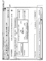
- the second dynamic widgets 2604 are selected in the third graphical user interface 2600, it is possible, for example, to set the desired temperature of the freezer compartment, which is done via a setting range 2700 shown in FIG . 27 , which in turn has static widgets 2701, 2702, 2703 and a temperature Settings widget 2704 contains the setting means 2704 for specifying the target temperature of the freezer compartment.
- the information in the configuration files is stored in XML format. There are a first configuration file to describe the page structure, and a second Configuration file for the definition of events. About language independence To ensure all text are saved in their own Java property files and by read in there.
- This structure divides the GUI into different views and areas.
- Each of the elements can contain any number of detail elements, as follows
- the Widget Call Element arranges a selected widget on the page and specifies the necessary parameters, which are then replaced by the current device values (dynamic detail date).
- Any HTML code can be inserted using the plain element.
- This configuration file turns an event index into a Java Script Command assigned, which is transmitted to the browser via an event channel.
- a corresponding device model is created as well as a device view object.
- the device view object now reads the supplied configuration files and transfers them to the request processor. This evaluates and generates the information in the file using an XML parser an object structure with the individual elements of the page. Thereby the texts are made uses the Java property files for the selected language.
- a user makes a request to the building gateway computing device through a browser 201 made, this request is from the request processor to Device view object forwarded.
- the Placeholder for the device values replaced by the real values.
Landscapes
- Engineering & Computer Science (AREA)
- Software Systems (AREA)
- Theoretical Computer Science (AREA)
- General Engineering & Computer Science (AREA)
- Physics & Mathematics (AREA)
- General Physics & Mathematics (AREA)
- Human Computer Interaction (AREA)
- Automation & Control Theory (AREA)
- Computer Networks & Wireless Communication (AREA)
- Signal Processing (AREA)
- Multimedia (AREA)
- Stored Programmes (AREA)
- User Interface Of Digital Computer (AREA)
- Debugging And Monitoring (AREA)
- Data Exchanges In Wide-Area Networks (AREA)
Applications Claiming Priority (2)
| Application Number | Priority Date | Filing Date | Title |
|---|---|---|---|
| DE10208146A DE10208146A1 (de) | 2002-10-02 | 2002-02-26 | Verfahren zum rechnergestützten Erzeugen einer graphischen Benutzeroberfläche und Geräteüberwachungs-/Steuerungseinheit |
| DE10208146 | 2002-02-26 |
Publications (2)
| Publication Number | Publication Date |
|---|---|
| EP1341082A2 true EP1341082A2 (fr) | 2003-09-03 |
| EP1341082A3 EP1341082A3 (fr) | 2005-07-06 |
Family
ID=27674972
Family Applications (1)
| Application Number | Title | Priority Date | Filing Date |
|---|---|---|---|
| EP03003279A Ceased EP1341082A3 (fr) | 2002-02-26 | 2003-02-24 | Méthode pour la génération assistée par ordinateur d'une interface graphique d'utilisateur d'une unité de monitorisation ou de contrôle d'un appareil |
Country Status (1)
| Country | Link |
|---|---|
| EP (1) | EP1341082A3 (fr) |
Cited By (3)
| Publication number | Priority date | Publication date | Assignee | Title |
|---|---|---|---|---|
| WO2004034254A3 (fr) * | 2002-10-02 | 2005-06-30 | Bsh Bosch Siemens Hausgeraete | Procede et dispositif de commutation destines a la production assistee par ordinateur d'une interface utilisateur graphique |
| DE102005041363A1 (de) * | 2005-08-31 | 2007-03-01 | Siemens Ag | Verfahren und Geräte zum Steuern und Betreiben von elektrischen Geräten mit unterschiedlichen Funktionen |
| CN114629938A (zh) * | 2022-03-23 | 2022-06-14 | 杭州老板电器股份有限公司 | 一种中央吸油烟机系统及通讯方法 |
Citations (1)
| Publication number | Priority date | Publication date | Assignee | Title |
|---|---|---|---|---|
| US5793963A (en) * | 1994-10-24 | 1998-08-11 | Fisher Rosemount Systems, Inc. | Apparatus for providing non-redundant secondary access to field devices in a distributed control system |
Family Cites Families (1)
| Publication number | Priority date | Publication date | Assignee | Title |
|---|---|---|---|---|
| BR9906952A (pt) * | 1998-09-17 | 2000-10-03 | Koninkl Philips Electronics Nv | Processo para facilitar uma programação de um dispositivo de controle, programa de software que está contido em um meio legìvel por computador para execução em um computador, respectivo dispositivo de controle, software objeto que está contido em um meio legìvel por computador em um site de internet, e, processo de habilitação de um usuário para personalizar o controle de um aparelho |
-
2003
- 2003-02-24 EP EP03003279A patent/EP1341082A3/fr not_active Ceased
Patent Citations (1)
| Publication number | Priority date | Publication date | Assignee | Title |
|---|---|---|---|---|
| US5793963A (en) * | 1994-10-24 | 1998-08-11 | Fisher Rosemount Systems, Inc. | Apparatus for providing non-redundant secondary access to field devices in a distributed control system |
Non-Patent Citations (1)
| Title |
|---|
| HODES T D ET AL: "COMPOSABLE AD HOC LOCATION-BASED SERVICES FOR HETEROGENEOUS MOBILE CLIENTS", WIRELESS NETWORKS, ACM, 2 PENN PLAZA, SUITE 701 - NEW YORK USA, vol. 5, no. 5, 1 October 1999 (1999-10-01), pages 411 - 427, XP000902495, ISSN: 1022-0038, DOI: 10.1023/A:1019171616176 * |
Cited By (3)
| Publication number | Priority date | Publication date | Assignee | Title |
|---|---|---|---|---|
| WO2004034254A3 (fr) * | 2002-10-02 | 2005-06-30 | Bsh Bosch Siemens Hausgeraete | Procede et dispositif de commutation destines a la production assistee par ordinateur d'une interface utilisateur graphique |
| DE102005041363A1 (de) * | 2005-08-31 | 2007-03-01 | Siemens Ag | Verfahren und Geräte zum Steuern und Betreiben von elektrischen Geräten mit unterschiedlichen Funktionen |
| CN114629938A (zh) * | 2022-03-23 | 2022-06-14 | 杭州老板电器股份有限公司 | 一种中央吸油烟机系统及通讯方法 |
Also Published As
| Publication number | Publication date |
|---|---|
| EP1341082A3 (fr) | 2005-07-06 |
Similar Documents
| Publication | Publication Date | Title |
|---|---|---|
| EP1436676B1 (fr) | Procede permettant de faire fonctionner et d'observer des appareils utilisables in situ | |
| EP1436677B1 (fr) | Procede de mise en service d'un systeme de commande et de surveillance d'appareils de terrain | |
| DE10208146A1 (de) | Verfahren zum rechnergestützten Erzeugen einer graphischen Benutzeroberfläche und Geräteüberwachungs-/Steuerungseinheit | |
| DE10218536B4 (de) | Gerätekonfiguration in einer verteilten Umgebung | |
| DE69838439T2 (de) | Verfahren und Vorrichtung zur Überwachung von Geräten in einem Hausnetzwerk | |
| DE60029321T2 (de) | Verfahren und vorrichtung zur fernbedienung eines hausnetzwerks von einem externen kommunikationsnetz | |
| DE69801816T2 (de) | Vorrichtung und verfahren zur aktualisierung und zur synchronisierung von informationen zwischen einem klient und einem server | |
| DE69926368T2 (de) | Verfahren und vorrichtung für universellen zugriffsbefehl und kontrollinformation in einem netzwerk | |
| DE69833777T2 (de) | Webschnittstelle für eine programmierbare steuerung | |
| DE69819211T2 (de) | Verteilte interfacearchitektur einer programmierbaren industriellen steuerung | |
| DE60109029T2 (de) | Zugriff auf ein in-haus netzwerk über das internet | |
| DE60319362T2 (de) | Eingebetteter controller und entfernter server zum senden und wiederfinden von daten über ein neztwerk | |
| DE60003457T2 (de) | Verfahren und system zur konfiguration von komponenten, ausgebbar in einem netzwerk | |
| DE60006018T2 (de) | Drahtlose Steuerung eines Feldgerätes in einem industriellen Prozess | |
| DE69700074T2 (de) | Dynamische verbindbare Etiketten in einer Netzbrowserseite | |
| DE102004051179B4 (de) | Einstellungsvorrichtung für ein Steuerungssystem, Verfahren zum Einstellen eines Steuerungssystems und Einstellungsprogramm | |
| DE60211254T2 (de) | Fernereignis Behandlung in ein Paketnetzwerk | |
| DE69308942T2 (de) | Steuerungseinrichtung mit Übermittlung von Steuerungsstrukturdefinitionen | |
| DE69718556T2 (de) | Verfahren und Vorrichtung zur Kontrolle der Kommunikation elektronischer Geräte | |
| DE10049504B4 (de) | Verfahren und System zur tranparenten Unterstützung von entfernten Eingabe-/Ausgabeeinrichtungen in einem Prozeßsteuersystem | |
| DE10296841T5 (de) | Heim-Netzwerkübertragungssystem und Übertragungsverfahren unter Verwendung desselben | |
| DE602004009746T2 (de) | Teilen von Diensten in einem Netz | |
| EP1338961A2 (fr) | Procédé pour la génération d'un interface utilisateur assistée par ordinateur | |
| DE10323329B4 (de) | Kommunikationsverfahren und System, insbesondere für ein Heimnetzwerk | |
| DE10151119C2 (de) | Verfahren zum Erfassen von mehreren Feldgeräten in einer Gerätekonfiguration |
Legal Events
| Date | Code | Title | Description |
|---|---|---|---|
| PUAI | Public reference made under article 153(3) epc to a published international application that has entered the european phase |
Free format text: ORIGINAL CODE: 0009012 |
|
| AK | Designated contracting states |
Kind code of ref document: A2 Designated state(s): AT BE BG CH CY CZ DE DK EE ES FI FR GB GR HU IE IT LI LU MC NL PT SE SI SK TR |
|
| AX | Request for extension of the european patent |
Extension state: AL LT LV MK RO |
|
| RIN1 | Information on inventor provided before grant (corrected) |
Inventor name: RITTER, JOACHIM Inventor name: WITTE, SEBASTIAN Inventor name: ELLINGER, MICHAEL Inventor name: ENGL, PETER |
|
| RAP1 | Party data changed (applicant data changed or rights of an application transferred) |
Owner name: BSH BOSCH UND SIEMENS HAUSGERAETE GMBH |
|
| PUAL | Search report despatched |
Free format text: ORIGINAL CODE: 0009013 |
|
| AK | Designated contracting states |
Kind code of ref document: A3 Designated state(s): AT BE BG CH CY CZ DE DK EE ES FI FR GB GR HU IE IT LI LU MC NL PT SE SI SK TR |
|
| AX | Request for extension of the european patent |
Extension state: AL LT LV MK RO |
|
| 17P | Request for examination filed |
Effective date: 20060109 |
|
| AKX | Designation fees paid |
Designated state(s): AT BE BG CH CY CZ DE DK EE ES FI FR GB GR HU IE IT LI LU MC NL PT SE SI SK TR |
|
| 17Q | First examination report despatched |
Effective date: 20060620 |
|
| RAP1 | Party data changed (applicant data changed or rights of an application transferred) |
Owner name: BSH HAUSGERAETE GMBH |
|
| STAA | Information on the status of an ep patent application or granted ep patent |
Free format text: STATUS: THE APPLICATION HAS BEEN REFUSED |
|
| 18R | Application refused |
Effective date: 20180427 |