EP1341482B2 - Stent mit spiralen elementen - Google Patents
Stent mit spiralen elementen Download PDFInfo
- Publication number
- EP1341482B2 EP1341482B2 EP01992086.7A EP01992086A EP1341482B2 EP 1341482 B2 EP1341482 B2 EP 1341482B2 EP 01992086 A EP01992086 A EP 01992086A EP 1341482 B2 EP1341482 B2 EP 1341482B2
- Authority
- EP
- European Patent Office
- Prior art keywords
- stent
- segments
- circumferential
- cylindrical
- elements
- Prior art date
- Legal status (The legal status is an assumption and is not a legal conclusion. Google has not performed a legal analysis and makes no representation as to the accuracy of the status listed.)
- Expired - Lifetime
Links
Images




Classifications
-
- A—HUMAN NECESSITIES
- A61—MEDICAL OR VETERINARY SCIENCE; HYGIENE
- A61F—FILTERS IMPLANTABLE INTO BLOOD VESSELS; PROSTHESES; DEVICES PROVIDING PATENCY TO, OR PREVENTING COLLAPSING OF, TUBULAR STRUCTURES OF THE BODY, e.g. STENTS; ORTHOPAEDIC, NURSING OR CONTRACEPTIVE DEVICES; FOMENTATION; TREATMENT OR PROTECTION OF EYES OR EARS; BANDAGES, DRESSINGS OR ABSORBENT PADS; FIRST-AID KITS
- A61F2/00—Filters implantable into blood vessels; Prostheses, i.e. artificial substitutes or replacements for parts of the body; Appliances for connecting them with the body; Devices providing patency to, or preventing collapsing of, tubular structures of the body, e.g. stents
- A61F2/82—Devices providing patency to, or preventing collapsing of, tubular structures of the body, e.g. stents
- A61F2/86—Stents in a form characterised by the wire-like elements; Stents in the form characterised by a net-like or mesh-like structure
- A61F2/90—Stents in a form characterised by the wire-like elements; Stents in the form characterised by a net-like or mesh-like structure characterised by a net-like or mesh-like structure
- A61F2/91—Stents in a form characterised by the wire-like elements; Stents in the form characterised by a net-like or mesh-like structure characterised by a net-like or mesh-like structure made from perforated sheets or tubes, e.g. perforated by laser cuts or etched holes
- A61F2/915—Stents in a form characterised by the wire-like elements; Stents in the form characterised by a net-like or mesh-like structure characterised by a net-like or mesh-like structure made from perforated sheets or tubes, e.g. perforated by laser cuts or etched holes with bands having a meander structure, adjacent bands being connected to each other
-
- A—HUMAN NECESSITIES
- A61—MEDICAL OR VETERINARY SCIENCE; HYGIENE
- A61F—FILTERS IMPLANTABLE INTO BLOOD VESSELS; PROSTHESES; DEVICES PROVIDING PATENCY TO, OR PREVENTING COLLAPSING OF, TUBULAR STRUCTURES OF THE BODY, e.g. STENTS; ORTHOPAEDIC, NURSING OR CONTRACEPTIVE DEVICES; FOMENTATION; TREATMENT OR PROTECTION OF EYES OR EARS; BANDAGES, DRESSINGS OR ABSORBENT PADS; FIRST-AID KITS
- A61F2/00—Filters implantable into blood vessels; Prostheses, i.e. artificial substitutes or replacements for parts of the body; Appliances for connecting them with the body; Devices providing patency to, or preventing collapsing of, tubular structures of the body, e.g. stents
- A61F2/82—Devices providing patency to, or preventing collapsing of, tubular structures of the body, e.g. stents
- A61F2/86—Stents in a form characterised by the wire-like elements; Stents in the form characterised by a net-like or mesh-like structure
- A61F2/90—Stents in a form characterised by the wire-like elements; Stents in the form characterised by a net-like or mesh-like structure characterised by a net-like or mesh-like structure
- A61F2/91—Stents in a form characterised by the wire-like elements; Stents in the form characterised by a net-like or mesh-like structure characterised by a net-like or mesh-like structure made from perforated sheets or tubes, e.g. perforated by laser cuts or etched holes
- A61F2/915—Stents in a form characterised by the wire-like elements; Stents in the form characterised by a net-like or mesh-like structure characterised by a net-like or mesh-like structure made from perforated sheets or tubes, e.g. perforated by laser cuts or etched holes with bands having a meander structure, adjacent bands being connected to each other
- A61F2002/91508—Stents in a form characterised by the wire-like elements; Stents in the form characterised by a net-like or mesh-like structure characterised by a net-like or mesh-like structure made from perforated sheets or tubes, e.g. perforated by laser cuts or etched holes with bands having a meander structure, adjacent bands being connected to each other the meander having a difference in amplitude along the band
-
- A—HUMAN NECESSITIES
- A61—MEDICAL OR VETERINARY SCIENCE; HYGIENE
- A61F—FILTERS IMPLANTABLE INTO BLOOD VESSELS; PROSTHESES; DEVICES PROVIDING PATENCY TO, OR PREVENTING COLLAPSING OF, TUBULAR STRUCTURES OF THE BODY, e.g. STENTS; ORTHOPAEDIC, NURSING OR CONTRACEPTIVE DEVICES; FOMENTATION; TREATMENT OR PROTECTION OF EYES OR EARS; BANDAGES, DRESSINGS OR ABSORBENT PADS; FIRST-AID KITS
- A61F2/00—Filters implantable into blood vessels; Prostheses, i.e. artificial substitutes or replacements for parts of the body; Appliances for connecting them with the body; Devices providing patency to, or preventing collapsing of, tubular structures of the body, e.g. stents
- A61F2/82—Devices providing patency to, or preventing collapsing of, tubular structures of the body, e.g. stents
- A61F2/86—Stents in a form characterised by the wire-like elements; Stents in the form characterised by a net-like or mesh-like structure
- A61F2/90—Stents in a form characterised by the wire-like elements; Stents in the form characterised by a net-like or mesh-like structure characterised by a net-like or mesh-like structure
- A61F2/91—Stents in a form characterised by the wire-like elements; Stents in the form characterised by a net-like or mesh-like structure characterised by a net-like or mesh-like structure made from perforated sheets or tubes, e.g. perforated by laser cuts or etched holes
- A61F2/915—Stents in a form characterised by the wire-like elements; Stents in the form characterised by a net-like or mesh-like structure characterised by a net-like or mesh-like structure made from perforated sheets or tubes, e.g. perforated by laser cuts or etched holes with bands having a meander structure, adjacent bands being connected to each other
- A61F2002/91516—Stents in a form characterised by the wire-like elements; Stents in the form characterised by a net-like or mesh-like structure characterised by a net-like or mesh-like structure made from perforated sheets or tubes, e.g. perforated by laser cuts or etched holes with bands having a meander structure, adjacent bands being connected to each other the meander having a change in frequency along the band
-
- A—HUMAN NECESSITIES
- A61—MEDICAL OR VETERINARY SCIENCE; HYGIENE
- A61F—FILTERS IMPLANTABLE INTO BLOOD VESSELS; PROSTHESES; DEVICES PROVIDING PATENCY TO, OR PREVENTING COLLAPSING OF, TUBULAR STRUCTURES OF THE BODY, e.g. STENTS; ORTHOPAEDIC, NURSING OR CONTRACEPTIVE DEVICES; FOMENTATION; TREATMENT OR PROTECTION OF EYES OR EARS; BANDAGES, DRESSINGS OR ABSORBENT PADS; FIRST-AID KITS
- A61F2/00—Filters implantable into blood vessels; Prostheses, i.e. artificial substitutes or replacements for parts of the body; Appliances for connecting them with the body; Devices providing patency to, or preventing collapsing of, tubular structures of the body, e.g. stents
- A61F2/82—Devices providing patency to, or preventing collapsing of, tubular structures of the body, e.g. stents
- A61F2/86—Stents in a form characterised by the wire-like elements; Stents in the form characterised by a net-like or mesh-like structure
- A61F2/90—Stents in a form characterised by the wire-like elements; Stents in the form characterised by a net-like or mesh-like structure characterised by a net-like or mesh-like structure
- A61F2/91—Stents in a form characterised by the wire-like elements; Stents in the form characterised by a net-like or mesh-like structure characterised by a net-like or mesh-like structure made from perforated sheets or tubes, e.g. perforated by laser cuts or etched holes
- A61F2/915—Stents in a form characterised by the wire-like elements; Stents in the form characterised by a net-like or mesh-like structure characterised by a net-like or mesh-like structure made from perforated sheets or tubes, e.g. perforated by laser cuts or etched holes with bands having a meander structure, adjacent bands being connected to each other
- A61F2002/91525—Stents in a form characterised by the wire-like elements; Stents in the form characterised by a net-like or mesh-like structure characterised by a net-like or mesh-like structure made from perforated sheets or tubes, e.g. perforated by laser cuts or etched holes with bands having a meander structure, adjacent bands being connected to each other within the whole structure different bands showing different meander characteristics, e.g. frequency or amplitude
-
- A—HUMAN NECESSITIES
- A61—MEDICAL OR VETERINARY SCIENCE; HYGIENE
- A61F—FILTERS IMPLANTABLE INTO BLOOD VESSELS; PROSTHESES; DEVICES PROVIDING PATENCY TO, OR PREVENTING COLLAPSING OF, TUBULAR STRUCTURES OF THE BODY, e.g. STENTS; ORTHOPAEDIC, NURSING OR CONTRACEPTIVE DEVICES; FOMENTATION; TREATMENT OR PROTECTION OF EYES OR EARS; BANDAGES, DRESSINGS OR ABSORBENT PADS; FIRST-AID KITS
- A61F2/00—Filters implantable into blood vessels; Prostheses, i.e. artificial substitutes or replacements for parts of the body; Appliances for connecting them with the body; Devices providing patency to, or preventing collapsing of, tubular structures of the body, e.g. stents
- A61F2/82—Devices providing patency to, or preventing collapsing of, tubular structures of the body, e.g. stents
- A61F2/86—Stents in a form characterised by the wire-like elements; Stents in the form characterised by a net-like or mesh-like structure
- A61F2/90—Stents in a form characterised by the wire-like elements; Stents in the form characterised by a net-like or mesh-like structure characterised by a net-like or mesh-like structure
- A61F2/91—Stents in a form characterised by the wire-like elements; Stents in the form characterised by a net-like or mesh-like structure characterised by a net-like or mesh-like structure made from perforated sheets or tubes, e.g. perforated by laser cuts or etched holes
- A61F2/915—Stents in a form characterised by the wire-like elements; Stents in the form characterised by a net-like or mesh-like structure characterised by a net-like or mesh-like structure made from perforated sheets or tubes, e.g. perforated by laser cuts or etched holes with bands having a meander structure, adjacent bands being connected to each other
- A61F2002/91533—Stents in a form characterised by the wire-like elements; Stents in the form characterised by a net-like or mesh-like structure characterised by a net-like or mesh-like structure made from perforated sheets or tubes, e.g. perforated by laser cuts or etched holes with bands having a meander structure, adjacent bands being connected to each other characterised by the phase between adjacent bands
-
- A—HUMAN NECESSITIES
- A61—MEDICAL OR VETERINARY SCIENCE; HYGIENE
- A61F—FILTERS IMPLANTABLE INTO BLOOD VESSELS; PROSTHESES; DEVICES PROVIDING PATENCY TO, OR PREVENTING COLLAPSING OF, TUBULAR STRUCTURES OF THE BODY, e.g. STENTS; ORTHOPAEDIC, NURSING OR CONTRACEPTIVE DEVICES; FOMENTATION; TREATMENT OR PROTECTION OF EYES OR EARS; BANDAGES, DRESSINGS OR ABSORBENT PADS; FIRST-AID KITS
- A61F2/00—Filters implantable into blood vessels; Prostheses, i.e. artificial substitutes or replacements for parts of the body; Appliances for connecting them with the body; Devices providing patency to, or preventing collapsing of, tubular structures of the body, e.g. stents
- A61F2/82—Devices providing patency to, or preventing collapsing of, tubular structures of the body, e.g. stents
- A61F2/86—Stents in a form characterised by the wire-like elements; Stents in the form characterised by a net-like or mesh-like structure
- A61F2/90—Stents in a form characterised by the wire-like elements; Stents in the form characterised by a net-like or mesh-like structure characterised by a net-like or mesh-like structure
- A61F2/91—Stents in a form characterised by the wire-like elements; Stents in the form characterised by a net-like or mesh-like structure characterised by a net-like or mesh-like structure made from perforated sheets or tubes, e.g. perforated by laser cuts or etched holes
- A61F2/915—Stents in a form characterised by the wire-like elements; Stents in the form characterised by a net-like or mesh-like structure characterised by a net-like or mesh-like structure made from perforated sheets or tubes, e.g. perforated by laser cuts or etched holes with bands having a meander structure, adjacent bands being connected to each other
- A61F2002/9155—Adjacent bands being connected to each other
- A61F2002/91558—Adjacent bands being connected to each other connected peak to peak
-
- A—HUMAN NECESSITIES
- A61—MEDICAL OR VETERINARY SCIENCE; HYGIENE
- A61F—FILTERS IMPLANTABLE INTO BLOOD VESSELS; PROSTHESES; DEVICES PROVIDING PATENCY TO, OR PREVENTING COLLAPSING OF, TUBULAR STRUCTURES OF THE BODY, e.g. STENTS; ORTHOPAEDIC, NURSING OR CONTRACEPTIVE DEVICES; FOMENTATION; TREATMENT OR PROTECTION OF EYES OR EARS; BANDAGES, DRESSINGS OR ABSORBENT PADS; FIRST-AID KITS
- A61F2/00—Filters implantable into blood vessels; Prostheses, i.e. artificial substitutes or replacements for parts of the body; Appliances for connecting them with the body; Devices providing patency to, or preventing collapsing of, tubular structures of the body, e.g. stents
- A61F2/82—Devices providing patency to, or preventing collapsing of, tubular structures of the body, e.g. stents
- A61F2/86—Stents in a form characterised by the wire-like elements; Stents in the form characterised by a net-like or mesh-like structure
- A61F2/90—Stents in a form characterised by the wire-like elements; Stents in the form characterised by a net-like or mesh-like structure characterised by a net-like or mesh-like structure
- A61F2/91—Stents in a form characterised by the wire-like elements; Stents in the form characterised by a net-like or mesh-like structure characterised by a net-like or mesh-like structure made from perforated sheets or tubes, e.g. perforated by laser cuts or etched holes
- A61F2/915—Stents in a form characterised by the wire-like elements; Stents in the form characterised by a net-like or mesh-like structure characterised by a net-like or mesh-like structure made from perforated sheets or tubes, e.g. perforated by laser cuts or etched holes with bands having a meander structure, adjacent bands being connected to each other
- A61F2002/9155—Adjacent bands being connected to each other
- A61F2002/91583—Adjacent bands being connected to each other by a bridge, whereby at least one of its ends is connected along the length of a strut between two consecutive apices within a band
Definitions
- the present invention relates to prosthetic stents.
- the present invention relates to stents having helical elements.
- Stents are prosthetic devices that are implanted in the lumen of a vessel inside the body to provide support for the vessel's wall. Structural support from stents is particularly important in angioplasty procedures. Typically, stents are implanted within a vessel system to reinforce vessels that are partially occluded, collapsing, weakened, or abnormally dilated. More generally, stents can be used inside any physiological conduit or duct including, for example, arteries, veins, bile ducts, the urinary tract, alimentary tracts, the tracheobronchial tree, a cerebral aqueduct or the genitourinary system. Stents may be used in both humans and animals.
- Self expanding stents automatically expand once they are released and assume a deployed, expanded state.
- a balloon expandable stent is expanded using an inflatable balloon catheter.
- the balloon is inflated to plastically deform the stent
- Balloon expandable stents may be implanted by mounting the stent in an unexpanded or crimped state on a balloon segment of a catheter.
- the catheter after having the crimped stent placed thereon, is inserted through a puncture in a vessel wall and moved through the vessel until it is positioned in the portion of the vessel that is in need of repair.
- the stent is then expanded by inflating the balloon catheter against the inside wall of the vessel.
- the stent is plastically deformed by inflating the balloon so that the diameter of the stent is increased and remains at an increased state.
- the vessel in which the stent is implanted may be dilated by the stent itself when the stent is expanded.
- Palmaz-Schatz tm stent which is disclosed in the Handbook of Coronary Stents by Patrick W. Serruys et al. (Martin Dunitz, LTD 1998 ), is an example of a balloon expandable stent that had been implanted in hundreds of thousands of patients.
- the Palmaz-Schatz tm stent like other known stents, has certain limitations.
- Stent-to-vessel ratio generally refers to the degree that the vessel wall is supported by the stent in its expanded state and preferably should be uniform throughout the length of the stent.
- Palmaz-Schatz tm stent consists of one or more bridges that connect a number of consecutively slotted tubes, there are a number of bare areas in the vessel after the expansion of the stent These shortfalls arc common to many stents.
- EP-A-0 884 029 discloses an expandable stent comprising a main body, wherein the main body has a generally cylindrical shape and a cylindrical axis and, when the stent is unexpanded, the main body comprises a plurality of expandable helical segments.
- the present invention provides a stent according to claim 1.
- the present invention is directed to expandable stents that have relatively uniform stent-to-vessel ratios when expanded and other desirable properties.
- the stents of the present invention comprise a generally cylindrically shaped main body having a plurality of expandable helical segments.
- the main body is comprised of a plurality of cylindrical main body elements that are joined together by the helical segments.
- the cylindrical elements have cylindrical axes that are collinear with the cylindrical axis of the main body.
- the cylindrical elements are formed from a plurality of circumferential elements that are joined together by the expandable helical segments.
- the stent may comprise endzones that straddle the main body.
- the stent may comprise a first non-helical endzone and a second non-helical endzone that straddle the main body.
- the main body is generally cylindrically shaped and has a cylindrical axis.
- a plurality of adjacent main body cylindrical elements are connected together to form the main body of the stent.
- Each main body cylindrical element is comprised of a plurality of expandable first and second circumferential elements.
- the second circumferential elements have a circumferential dimension less than the circumferential dimension of the first circumferential elements.
- Each second circumferential segment in each main body cylindrical element is connected to two first circumferential segments.
- each second circumferential segment in each main body cylindrical element is connected to a second circumferential segment in an adjoining main body cylindrical element thereby forming a plurality of helixes in the main body of the stent.
- the main body is comprised of a plurality of first helical segments each having a substantially identical first pitch and a plurality of second helical segments, each having a substantially identical second pitch.
- the first and second pitches are generally different.
- the second pitch is twice that of the first, and at least one first helical segment crosses one of the second helical segments.
- the stents of the present invention may be manufactured from a tubular member by removing material from the tube to form a first endzone region, a second endzone region, and a middle region. By removing material from the middle region a plurality of parallel helical segments will remain and a plurality of circumferential segments will remain connecting the helical segments.
- the stent may be formed from a tube by removing material such that at least two sets of helical segments remain with each set having a different pitch.
- the present invention is directed to an expandable stent.
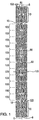
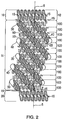
- the stent comprises a generally cylindrical shaped main body section 11 having a cylindrical axis 5 and a wall thickness 103.
- the wall thickness 103 may optionally be uniform throughout the stent.
- the main body section 11 is comprised of a plurality of helical segments 30 and 40 and a plurality of main body cylindrical elements 100, each having cylindrical axes (not shown) that are collinear with the main body cylindrical axis 5 .
- the main body cylindrical elements 100 are each comprised of circumferential elements 50 that are joined together by the helical segments 30 and 40 to form individual cylinders 100 .
- the stent may also have a first endzone 10 and a second endzone 20 that straddle the body section 11 .
- the endzones 10 and 20 may advantageously provide the stent with square outer edges 8.
- the stent may be manufactured from stainless steel, or other suitable materials. In most embodiments, it is desirable that the material, or a portion of the material, be radiopaque and that the various segments that form the stent be contiguous. Although, in some embodiments, the various segments that make up the stent can be distinct elements that are joined together.
- the main body 11, shown in Figures 1 and 2 may be formed in numerous ways.
- the body 11 contains two or more first helical segment 30 and 40 that are generally parallel to each other and an opposite each other by 180.° In general, the first helical segments 30 and 40 will be spaced equidistant along the circumference 110 of the main body 11.
- the first helical segments 30 and 40 are joined by a plurality of circumferential segments 50 to form a plurality main body cylindrical elements 100, which are generally cylindrically shaped.
- the circumferential segments 50 make up a majority of the circumference 110 of each cylindrical element 100.
- the helical segments 30 and 40 connect each cylindrical element 100 to an adjacent cylindrical element 100 to form the main body 11 .
- the body of the stent 11 comprises a plurality of main body cylindrical elements 100 formed from first circumferential segments 50 that are joined with second circumferential segments 60.
- the second circumferential segments 60 of each cylindrical element 100 are joined with second circum-ferential segments 60 of adjacent cylindrical elements 100 to form a plurality of first helical segments 30 and 40 in the main body 11.
- Each first circumferential segment 50 may have a circumferential dimension 55 and each second circumferential segments 60 may have a circumferential dimension 66. (See Fig.3 )
- the first circumferential segment 50 is an expandable segment formed from plurality of segments joined together to form a repeating pattern.
- the pattern such as the one shown in the figures 1-3 , may be a repeating pattern that resembles a square wave form having curved peaks and valleys. Other repeating patterns, may be used that enable the segment to expand when a radial force is exerted on the stent from the inside or collapse radially when an external crimping force is applied.
- the first circumferential elements 50 may have a filament width 420 (see Fig. 4 ).
- the filament width may vary between 0.05 mm (0.002 inches) and 0.18 mm (0.007 inches), but is preferably about 0.13 mm (0.0050 inches). Other filament widths may be used depending on the parameters of the stent.
- the first circumferential elements 50 comprise linear portions 320 and curved portions 328 that join the linear portions 320 together to form a repeating pattern.
- the linear portion 320 may be parallel to the cylindrical axis of the stent.
- the first circumferential segment 50 has an amplitude 350 and a period 380.
- the amplitude may range from 0.5 mm to 2.0 mm and the period may range from 0.5 mm to 2.0 mm. In some embodiments, the amplitude is less than the period. Other amplitudes and periods may be used depending on the overall stent design and performance constraints.
- the second circumferential elements 60 are joined together in a helical pattern to form one of two helical segments 30 or 40 .
- the second circumferential element 60 comprises linear portions 412 and curved portions 414 having a filament width 407, and resembles generally an S-shaped structure.
- the second element circumferential segment 60 may have an angled portion 417 attached to the linear portion 412 at an end opposite that of the curved portion 414.
- the angled portion may be oriented to form an angle ⁇ relative to the cylindrical axis of the stent 5 in range of 0-45 degrees. In at least one example, the preferable angle ⁇ is about 10 degrees.
- the linear portions 412 of the second circumferential element 60 lies at an angle ⁇ relative to the cylindrical axis of the stent, wherein ⁇ preferably ranges from 0 to 45 degrees.
- the linear portions 412 may, in some embodiments, form an angle ⁇ , relative to the cylindrical axis of the stent in some examples, ⁇ may be approximately equal to the helical angle of the first helical segments 30 and 40.
- the second circumferential elements 60 may have an amplitude 300 (see Figs. 3 , 4 , and 6 ) ranging from 0.5 mm to 2.0 mm and a period ranging from 0.5 mm to 2.0 mm.
- the preferred period is about 0.82 mm and the preferred length of the linear portion 412 is about 0.5 mm and the amplitude 300 is about 0.38 mm.
- the amplitude of the second circumferential element 60 may be greater than, equal to, or less than the amplitude of the first circumferential element 50 .
- the circumferential contributions of the first circumferential elements 50 to the overall circumference of the main body 11 is greater than the circumferential contribution of the second circumferential element 60 , in terms of either circumferential length or circumferential cylindrical surface area.
- the stent may have an overall outer surface area of about 0.029 square inches.
- the stent has a main body 11 comprised of two first helical segments 30 and 40, as well as two second helical segments 200 and 210.
- the first and second helical segments 30, 40 and 200, 210, respectively, are joined together to form a generally cylindrically shaped body 11.
- the first and second helical segments share a common connecting element 250.
- the common connecting element 250 may be H-shaped and the two generally parallel linear portions of the H-shaped connecting segment 250 may form an angle ⁇ relative to the axis 5. (See Fig. 6 ).
- ⁇ may, in one example, be about 14 degrees.
- the first helical segments 30 and 40 and second helical segments 200 and 210 may have different pitches, i.e. number of spirals per unit length, which results in the first and second helical segments as having different helical angles ( ⁇ and ⁇ , respectively) i.e. the angle of the helical segment relative to the cylindrical axis 5 of the stent.
- the second helical segments 200 and 210 have a pitch approximately twice that of the first helical segments.
- ⁇ may vary from 0 to 45 degrees and is preferably about 40 degrees and P is preferably about twice ⁇ .
- the angle ⁇ may range from 0 to 90 degrees to the circumference 110 of each cylindrical element 100.
- the helical segments 30, 40 are circumferentially expandable (i.e. they expand along the circumference of the stent) and are formed from a plurality of circumferential elements 60 that in turn are made up of linear 412 and/or curved 414 segments (see Fig. 6 ) that each have a filament width 407 (see Fig. 6 ) that is less than the circumferential dimension 66 of the circumferential element 60 (see Fig. 3 ).
- each helical segment 30 or 40 will make a total contribution to the circumference of each cylindrical element 100 that is greater than the filament width 407.
- each helical segment 30 or 40 may be greater than the circumferential contribution of the filament widths 407 of the segments (e.g. 412 and 414) making up the circumferential elements 60 that in turn make up the helical segments.
- the circumferential contribution of the helical segments 30 and 40 to the circumference 110 of each cylindrical element 100 is more than just a function of the filament width 407, e.g., it may be a function of the geometry of the element 60.
- the geometry of the helical segments 30 and 40 are a factor in determining their expandability.
- the helical segments 200, 210 are circumferentially expandable and are comprised of other circumferential elements 50 that are in turn comprised of linear 320 and/or curved segments 328 (see Figs. 3 and 5 ) that have a filament width 420 (see Fig. 4 ).
- the contribution of the helical segments 200, 210 to the over-all circumferential dimension 110 of each cylindrical element 100 is greater than just the contribution of the filament widths 420 of the individual segments 320 and 328 that make up the elements 50 that in turn make up the helical segments 200, 210.
- the geometry of the elements 50 making up the helical segments 200, 210 may be a more important factor in determining the circumferential contribution of the helical segments 200 and 210 to the overall stent circumference than the filament width 420.
- the circumference of the stent 110 in its unexpanded state and the circumference 105 when the stent is expanded are primarily functions of the geometry of the elements 50 and 60 that make up the helical segments 30, 40 and 200 , 210, respectively.
- endzones 10 and 20 may employ endzones 10 and 20. (See Figs. 1 , 2 , and 11 ). Stents that employ endzones will generally have two endzone regions straddling a central zone in the middle of the stent. The stents may also have a transition region between the endzone and the central zone. The transition region serves to help smoothly transition between the expanded middle region and an portions of the end of the stent that remain unexpanded after the stent is implanted. The size and characteristics of the transition region are a function of the material and geometry of the stent.
- the transition range properties vary as a function of, among other things, the helical angle of the first helical segments, the number of curved segments located in the endzones, and the angle ⁇ of the linear portions of the segments forming the endzones. (See e.g. Fig. 8 ).
- the endzones 10 and 20 may take numerous form.
- the endzones may be comprised of one or more rings 17. (See Fig. 8 ).
- the rings 17 may be generally cylindrically shaped, and in some embodiments, right cylindrically shaped.
- the rings are formed from linear segments 28 joined together by curved segments 29 to form a pattern.
- the pattern which is preferably - but not necessarily - a repeating pattern may take numerous forms, including the one shown.
- the endzones 10 and 20 may be comprised of a plurality of rings 17 attached together.
- Struts 15 may be used to attach the rings together to form the endzone and to attach the endzone to the main body 11 .
- the struts in some examples, act as cantilever springs and there stiffness, which is a function of their width and thickness, may define bending properties of the stent along its cylindrical axis 5 .
- the linear segments 28 in the endzone 10 are oriented at an angle ⁇ relative to the cylindrical axis of the stent.
- the angle ⁇ may range from 0 to 45 degrees and in one embodiment is preferably about 10 degrees.
- the segments of the endzone may have a filament width 13 of between 0.05 and 0.18 mm (0.002 and 0.007 inches).
- the repeating pattern of the endzone has a period 2 of about 0.68 mm (0.027 inches) and an amplitude 21 of about 1.59 mm (0.043 inches) Other values may be used.
- the struts 15, which are but one way to attach the endzones 10 and 20 to the main body 11, may, in one embodiment have a width of between 0.05 mm (0.002 inches) and 2.03 mm (0.08 inches) and preferably the width does not exceed the wall thickness, which typically -but not necessarily ranges from about 0.05 to 0.02 mm (0.002 to 0.008 inches).
- the stent of the present invention may, after insertion into a vessel, be expanded such that it plastically deforms from the unexpanded state to an expanded state having a diameter increase of about 400 to 500%, which results in a larger circumference 105.
- Figure 11 depicts the stent shown in Figure 1 in an expanded state.
- the stent's outer diameter in one particular embodiment increases from 1.0 mm to 3.00 mm and maintains a stent-to-vessel ratio in the expanded state that is greater than on average 16%.
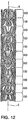
- Figures 12-15 depict an endzoneless stent Like the stent shown in Figures 1-9 , the stent of Figures 12-15 , comprises a plurality of adjacent cylindrical elements 100.
- the cylindrical elements 100 are formed from a plurality of first circumferential elements 50' and second circumferential elements 60.
- the first circumferential elements 50' of the stent in Figures 12-15 are substantially identical to the second circumferential element 60 except that they are rotated to have a different orientation.
- the circumferential elements may be generally S-shaped having a linear portion 412, a curved portion 414 having a radius R, and an angled portion 417.
- R may-vary widely depending on overall stent characteristics and in one embodiment varies between 0.02 and 0.5 mm (0.001 and 0.02 inches) and is preferably about 0.21 mm (0.0083 inches).
- the angled portion 417 is spaced a distance 499 from the linear portion. In one particular example, the distance 499 may vary from 0.002 to 0.020 inches and is preferably about 0.007 inches.
- the filament width 407 of the elements may, in one embodiment, be about 0.13 mm.
- Adjacent cylindrical elements 100 are joined together by connecting first circumferential elements 50' in each cylindrical element 100 with first circumferential elements 50' in an adjacent cylindrical element 100, such that the first circumferential elements 50' in adjacent cylindrical elements 100 form helixes through the stent and such that second circumferential elements form helixes through the stent having an angle ⁇ relative to the axis 5 .
- a connecting segment 250 (see Fig. 7 ) is used to connect first circumferential elements in adjacent cylindrical elements 100 and to connect second circumferential elements 60 in adjacent cylindrical elements 100.
- the connecting segment connects first circumferential elements 50 ' in each cylindrical element 100 with two second circumferential elements 60 in each cylindrical element 100.
- the individual cylindrical elements 100 are adjacent to each other and are located a distance 666 apart. In one embodiment, the preferred may range between 0.05 and 0.5 mm (0.002 and 0.020 inches), and is preferably about 0.009 inches.
- the stent of the present invention may be manufactured in numerous ways.
- the stent may be formed from a metallic tube by removing various portions of the tube's wall to form the patterns described herein.
- the resulting stent will thus be formed from a single contiguous piece of material, eliminating the need for connecting various segments together.
- Material from the tube wall maybe removed using various techniques including laser (YAG laser for example), electrical discharge, chemical etching, metal cutting, a combination of these techniques, or other well known techniques. See e.g. U.S Patent Nos. 5,879,381 to Moriuchi et al. and 6,117,165 to Becker .
- the tube from which the stent is formed may have an internal diameter of about 3.0 mm, a wall thickness of about 1.0 mm and a length of about 30 mm. Tubes having other dimensions may be used. In particular, the length may be adapted to that of the diseased part of the lumen in which the stent is to be placed. This may avoid using separate stents to cover the total diseased area.
Landscapes
- Health & Medical Sciences (AREA)
- Engineering & Computer Science (AREA)
- Biomedical Technology (AREA)
- Heart & Thoracic Surgery (AREA)
- Life Sciences & Earth Sciences (AREA)
- Cardiology (AREA)
- Oral & Maxillofacial Surgery (AREA)
- Transplantation (AREA)
- Physics & Mathematics (AREA)
- Vascular Medicine (AREA)
- Optics & Photonics (AREA)
- Animal Behavior & Ethology (AREA)
- General Health & Medical Sciences (AREA)
- Public Health (AREA)
- Veterinary Medicine (AREA)
- Media Introduction/Drainage Providing Device (AREA)
- Prostheses (AREA)
- Materials For Medical Uses (AREA)
Claims (1)
- Expandierbarer Ballonstent, umfassend einen Hauptkörper (11) von im Wesentlichen zylindrischer Gestalt und mit zylindrischer Achse (5) und wobei, bei expandiertem Stent, der Hauptkörper eine Mehrzahl expandierbarer Spiralsegmente (30, 40) umfasst, wobei der Hauptkörper weiterhin eine Mehrzahl zylindrischer Hauptkörper-Elemente (100) umfasst mit koaxialen zylindrischen Achsen, wobei die zylindrischen Hauptkörperelemente (100) einander benachbart und durch spiralige Segmente (30, 40) aneinander befestigt sind, wobei jedes zylindrische Hauptkörperelement (100) einen Umfang (110) aufweist, der im Wesentlichen gleich jenem eines benachbarten zylindrischen Elementes ist, und umfassend eine Mehrzahl expandierbarer Umfangssegmente (50, 60), angeordnet zwischen aufeinanderfolgenden Verbindungselementen (250), die das zylindrische Element mit einem benachbarten zylindrischen Element verbindet, wobei die Umfangssegmente (50, 60) durch Teile der spiraligen Segmente (30, 40) miteinander verbunden sind, um die zylindrischen Elemente (100) zu bilden, wobei die Mehrzahl der Umfangssegmente (50, 60) einen Hauptteil des Umfanges (110) eines jeden zylindrischen Elementes (100) umfasst, dadurch gekennzeichnet, dass die zylindrischen Elemente (100) erste Umfangssegmente (50) umfassen, abwechselnd mit zweiten Umfangssegmenten (60), dass die zweiten Umfangssegmente im Wesentlichen S-förmige Struktur aufweisen mit drei linearen Teilen, die durch gekrümmte Teile miteinander verbunden sind, dass die ersten Umfangssegmente fünf Linearteile umfassen, verbunden miteinander durch vier gekrümmte Teile, dass einander benachbarte zylindrische Elemente miteinander verbunden sind durch zwei Anschlusselemente (250), dass die zweiten Umfangssegmente (60) einander benachbarter zylindrischer Elemente miteinander verbunden sind durch Anschlusselemente (250) zum Bilden eines von zwei ersten expandierbaren Spiralsegmenten (30, 40), dass die ersten Umfangssegmente (50) einander benachbarter zylindrischer Elemente miteinander verbunden sind durch Anschlusselemente (250) zum Bilden eines von zwei zweiten expandierbaren Spiralsegmenten (200, 210), dass die ersten expandierbaren Spiralsegmente (30, 40) im Wesentlichen parallel zueinander und 180° voneinander liegen, und dass die zweiten expandierbaren Spiralsegmente (200, 210) im Wesentlichen parallel zueinander und um 180° voneinander liegen, wobei die ersten Umfangselemente (50) lineare Teile (320) und gekrümmte Teile (328) umfassen, die die linearen Teile (320) miteinander verbinden, um ein Wiederholmuster zu bilden, und wobei die zweiten spiraligen Elemente die ersten spiraligen Elemente in anteiligen Verbindungselementen kreuzen.
Priority Applications (5)
| Application Number | Priority Date | Filing Date | Title |
|---|---|---|---|
| EP10184477.7A EP2311410B1 (de) | 2000-12-11 | 2001-12-11 | Stent mit Spiralen Elementen |
| EP15154813.8A EP2926775B1 (de) | 2000-12-11 | 2001-12-11 | Ballonexpandierbarer Stent |
| DK10184599.8T DK2311411T3 (en) | 2000-12-11 | 2001-12-11 | Stent having helical elements |
| EP10184636.8A EP2311412B2 (de) | 2000-12-11 | 2001-12-11 | Stent mit spiralförmigen Elementen |
| EP10184599.8A EP2311411B1 (de) | 2000-12-11 | 2001-12-11 | Stent mit Spiralen Elementen |
Applications Claiming Priority (3)
| Application Number | Priority Date | Filing Date | Title |
|---|---|---|---|
| US25468800P | 2000-12-11 | 2000-12-11 | |
| US254688P | 2000-12-11 | ||
| PCT/US2001/048034 WO2003017870A1 (en) | 2000-12-11 | 2001-12-11 | Stent having helical elements |
Related Child Applications (9)
| Application Number | Title | Priority Date | Filing Date |
|---|---|---|---|
| EP15154813.8A Division-Into EP2926775B1 (de) | 2000-12-11 | 2001-12-11 | Ballonexpandierbarer Stent |
| EP15154813.8A Division EP2926775B1 (de) | 2000-12-11 | 2001-12-11 | Ballonexpandierbarer Stent |
| EP10184636.8A Division EP2311412B2 (de) | 2000-12-11 | 2001-12-11 | Stent mit spiralförmigen Elementen |
| EP10184636.8A Division-Into EP2311412B2 (de) | 2000-12-11 | 2001-12-11 | Stent mit spiralförmigen Elementen |
| EP10184477.7A Division EP2311410B1 (de) | 2000-12-11 | 2001-12-11 | Stent mit Spiralen Elementen |
| EP10184477.7A Division-Into EP2311410B1 (de) | 2000-12-11 | 2001-12-11 | Stent mit Spiralen Elementen |
| EP10184599.8A Division EP2311411B1 (de) | 2000-12-11 | 2001-12-11 | Stent mit Spiralen Elementen |
| EP10184599.8A Division-Into EP2311411B1 (de) | 2000-12-11 | 2001-12-11 | Stent mit Spiralen Elementen |
| EP15157256 Division-Into | 2015-03-02 |
Publications (3)
| Publication Number | Publication Date |
|---|---|
| EP1341482A1 EP1341482A1 (de) | 2003-09-10 |
| EP1341482B1 EP1341482B1 (de) | 2010-10-20 |
| EP1341482B2 true EP1341482B2 (de) | 2016-05-18 |
Family
ID=22965184
Family Applications (5)
| Application Number | Title | Priority Date | Filing Date |
|---|---|---|---|
| EP10184477.7A Expired - Lifetime EP2311410B1 (de) | 2000-12-11 | 2001-12-11 | Stent mit Spiralen Elementen |
| EP10184636.8A Expired - Lifetime EP2311412B2 (de) | 2000-12-11 | 2001-12-11 | Stent mit spiralförmigen Elementen |
| EP01992086.7A Expired - Lifetime EP1341482B2 (de) | 2000-12-11 | 2001-12-11 | Stent mit spiralen elementen |
| EP15154813.8A Expired - Lifetime EP2926775B1 (de) | 2000-12-11 | 2001-12-11 | Ballonexpandierbarer Stent |
| EP10184599.8A Expired - Lifetime EP2311411B1 (de) | 2000-12-11 | 2001-12-11 | Stent mit Spiralen Elementen |
Family Applications Before (2)
| Application Number | Title | Priority Date | Filing Date |
|---|---|---|---|
| EP10184477.7A Expired - Lifetime EP2311410B1 (de) | 2000-12-11 | 2001-12-11 | Stent mit Spiralen Elementen |
| EP10184636.8A Expired - Lifetime EP2311412B2 (de) | 2000-12-11 | 2001-12-11 | Stent mit spiralförmigen Elementen |
Family Applications After (2)
| Application Number | Title | Priority Date | Filing Date |
|---|---|---|---|
| EP15154813.8A Expired - Lifetime EP2926775B1 (de) | 2000-12-11 | 2001-12-11 | Ballonexpandierbarer Stent |
| EP10184599.8A Expired - Lifetime EP2311411B1 (de) | 2000-12-11 | 2001-12-11 | Stent mit Spiralen Elementen |
Country Status (9)
| Country | Link |
|---|---|
| EP (5) | EP2311410B1 (de) |
| JP (1) | JP2004521720A (de) |
| CN (1) | CN1267067C (de) |
| AT (1) | ATE485014T1 (de) |
| DE (1) | DE60143308D1 (de) |
| DK (1) | DK2311411T3 (de) |
| ES (2) | ES2350630T3 (de) |
| PT (1) | PT2311411E (de) |
| WO (1) | WO2003017870A1 (de) |
Families Citing this family (52)
| Publication number | Priority date | Publication date | Assignee | Title |
|---|---|---|---|---|
| US7204848B1 (en) | 1995-03-01 | 2007-04-17 | Boston Scientific Scimed, Inc. | Longitudinally flexible expandable stent |
| US6290728B1 (en) | 1998-09-10 | 2001-09-18 | Percardia, Inc. | Designs for left ventricular conduit |
| US7033372B1 (en) | 1999-08-04 | 2006-04-25 | Percardia, Inc. | Corkscrew reinforced left ventricle to coronary artery channel |
| PT2311411E (pt) † | 2000-12-11 | 2015-11-17 | Orbusneich Medical Inc | Endoprótese com elementos helicoidais |
| US6976990B2 (en) | 2001-01-25 | 2005-12-20 | Percardia, Inc. | Intravascular ventriculocoronary bypass via a septal passageway |
| IL157276A0 (en) * | 2001-02-09 | 2004-02-19 | Orbus Medical Technologies Inc | Crimpable intraluminal endoprosthesis having helical elements |
| US6949118B2 (en) | 2002-01-16 | 2005-09-27 | Percardia, Inc. | Encased implant and methods |
| US7008397B2 (en) | 2002-02-13 | 2006-03-07 | Percardia, Inc. | Cardiac implant and methods |
| US7326219B2 (en) | 2002-09-09 | 2008-02-05 | Wilk Patent Development | Device for placing transmyocardial implant |
| GB0419954D0 (en) | 2004-09-08 | 2004-10-13 | Advotek Medical Devices Ltd | System for directing therapy |
| US7637939B2 (en) * | 2005-06-30 | 2009-12-29 | Boston Scientific Scimed, Inc. | Hybrid stent |
| USD597671S1 (en) | 2006-10-20 | 2009-08-04 | Orbusneich Medical, Inc. | Polymeric stent structure |
| USD568476S1 (en) | 2006-10-27 | 2008-05-06 | Orbusneich Medical, Inc. | Interlocking tubular stent structure |
| US8460364B2 (en) | 2006-07-20 | 2013-06-11 | Orbusneich Medical, Inc. | Bioabsorbable polymeric medical device |
| WO2008011614A2 (en) * | 2006-07-20 | 2008-01-24 | Orbusneich Medical, Inc. | Bioabsorbable polymeric medical device |
| JP5819197B2 (ja) * | 2009-02-02 | 2015-11-18 | コーディス・コーポレイションCordis Corporation | 可撓性ステント設計 |
| US9327060B2 (en) * | 2009-07-09 | 2016-05-03 | CARDINAL HEALTH SWITZERLAND 515 GmbH | Rapamycin reservoir eluting stent |
| CN102548512B (zh) * | 2009-09-18 | 2015-09-09 | 麦德托尼克瓦斯科尔勒公司 | 用于在螺旋支架上形成正交端部的方法 |
| JP2011156094A (ja) * | 2010-01-29 | 2011-08-18 | Nipro Corp | ステント |
| BR112013002638B8 (pt) | 2010-08-02 | 2021-02-23 | Cardinal Health 529 Llc | stent helicoidal flexível apresentando característica estrutural intermediária |
| US10231855B2 (en) | 2010-08-02 | 2019-03-19 | CARDINAL HEALTH SWITZERLAND 515 GmbH | Flexible helical stent having intermediate non-helical region |
| KR20160103151A (ko) | 2010-08-02 | 2016-08-31 | 코디스 코포레이션 | 상이한 나선형 영역들을 갖는 가요성 나선형 스텐트 |
| JP5889898B2 (ja) | 2010-08-02 | 2016-03-22 | コーディス・コーポレイションCordis Corporation | 突出するヒンジを有する可撓性ステント |
| US9364351B2 (en) * | 2012-04-23 | 2016-06-14 | Medtronic Vascular, Inc. | Method for forming a stent |
| WO2014066356A2 (en) * | 2012-10-22 | 2014-05-01 | Orbusneich Medical, Inc. | Medical device for implantation into luminal structures |
| DE102012111223A1 (de) * | 2012-11-21 | 2014-05-22 | Jotec Gmbh | Gefäßimplantat mit asymmetrischen Stentfedern |
| US9180031B2 (en) | 2013-03-15 | 2015-11-10 | Covidien Lp | Stent with varying radius between struts |
| US9259335B2 (en) | 2013-03-15 | 2016-02-16 | Covidien Lp | Stent |
| CN103462734A (zh) * | 2013-09-18 | 2013-12-25 | 深圳市金瑞凯利生物科技有限公司 | 冠脉血管支架及其制作方法 |
| US9980835B2 (en) | 2013-10-22 | 2018-05-29 | Orbusneich Medical Inc. | Medical device for implantation into luminal structures incorporating corrugated structural elements |
| JP6081948B2 (ja) | 2014-03-25 | 2017-02-15 | 株式会社World Medish Technology | 柔軟性ステント |
| US9545263B2 (en) | 2014-06-19 | 2017-01-17 | Limflow Gmbh | Devices and methods for treating lower extremity vasculature |
| US11541205B2 (en) | 2015-07-20 | 2023-01-03 | Roivios Limited | Coated urinary catheter or ureteral stent and method |
| US10493232B2 (en) | 2015-07-20 | 2019-12-03 | Strataca Systems Limited | Ureteral catheters, bladder catheters, systems, kits and methods for inducing negative pressure to increase renal function |
| US12064567B2 (en) | 2015-07-20 | 2024-08-20 | Roivios Limited | Percutaneous urinary catheter |
| US11229771B2 (en) | 2015-07-20 | 2022-01-25 | Roivios Limited | Percutaneous ureteral catheter |
| US11040172B2 (en) | 2015-07-20 | 2021-06-22 | Strataca Systems Limited | Ureteral and bladder catheters and methods of inducing negative pressure to increase renal perfusion |
| US10512713B2 (en) | 2015-07-20 | 2019-12-24 | Strataca Systems Limited | Method of removing excess fluid from a patient with hemodilution |
| US10926062B2 (en) | 2015-07-20 | 2021-02-23 | Strataca Systems Limited | Ureteral and bladder catheters and methods of inducing negative pressure to increase renal perfusion |
| US10918827B2 (en) | 2015-07-20 | 2021-02-16 | Strataca Systems Limited | Catheter device and method for inducing negative pressure in a patient's bladder |
| CN112691278B (zh) | 2015-07-20 | 2024-03-22 | 罗维奥斯有限公司 | 输尿管和膀胱导管及引入负压以增加肾灌注的方法 |
| US10905572B2 (en) | 2016-11-14 | 2021-02-02 | Covidien Lp | Stent |
| US10258488B2 (en) | 2016-11-14 | 2019-04-16 | Covidien Lp | Stent |
| US10449069B2 (en) | 2016-11-14 | 2019-10-22 | Covidien Lp | Stent |
| CN106880429B (zh) * | 2017-03-15 | 2019-01-01 | 大连理工大学 | 一种螺旋式血管支架 |
| WO2018189593A2 (en) | 2017-04-10 | 2018-10-18 | Limflow Gmbh | Devices and methods for treating lower extremity vasculature |
| CN110785201A (zh) * | 2017-04-25 | 2020-02-11 | 斯特拉塔卡系统有限公司 | 用于产生负压以增强肾功能的系统、套件和方法 |
| US11672680B2 (en) | 2017-08-11 | 2023-06-13 | The Charles Stark Draper Laboratory, Inc. | Growth adaptive expandable stent |
| MX2020002064A (es) | 2017-08-25 | 2020-10-16 | Roivios Ltd | Bomba permanente para facilitar la extracción de orina del tracto urinario. |
| WO2020076833A1 (en) | 2018-10-09 | 2020-04-16 | Limflow Gmbh | Devices and methods for catheter alignment |
| AU2020373046A1 (en) | 2019-11-01 | 2022-05-12 | Limflow Gmbh | Devices and methods for increasing blood perfusion to a distal extremity |
| US12472301B2 (en) | 2021-08-13 | 2025-11-18 | 3Ive Labs, Llc | Negative pressure therapy system and methods |
Citations (11)
| Publication number | Priority date | Publication date | Assignee | Title |
|---|---|---|---|---|
| WO1994017754A1 (de) † | 1993-02-04 | 1994-08-18 | Angiomed Ag | Stent |
| WO1995026695A2 (en) † | 1994-04-01 | 1995-10-12 | Prograft Medical, Inc. | Self-expandable stent and stent-graft and method of using them |
| WO1998020810A1 (en) † | 1996-11-12 | 1998-05-22 | Medtronic, Inc. | Flexible, radially expansible luminal prostheses |
| EP0876806A1 (de) † | 1997-05-05 | 1998-11-11 | Patrick Sabaria | Vaskuläre und koronare stents |
| WO1999039660A1 (fr) † | 1998-02-03 | 1999-08-12 | B. Braun Celsa | Endoprothese a etais longitudinaux ondules |
| EP0983753A1 (de) † | 1998-09-05 | 2000-03-08 | Jomed Implantate GmbH | Kompakter Stent |
| WO2000030563A1 (en) † | 1998-11-20 | 2000-06-02 | Scimed Life Systems, Inc. | Longitudinally flexible expandable stent |
| WO2000045742A1 (en) † | 1999-02-02 | 2000-08-10 | C.R. Bard, Inc. | Covered stent with encapsulated ends |
| US6132460A (en) † | 1998-03-27 | 2000-10-17 | Intratherapeutics, Inc. | Stent |
| WO2001089421A2 (en) † | 2000-05-22 | 2001-11-29 | Orbus Medical Technologies Inc. | Self-expanding stent |
| EP2311412B1 (de) † | 2000-12-11 | 2012-09-05 | OrbusNeich Medical, Inc. | Stent mit Spiralen Elementen |
Family Cites Families (18)
| Publication number | Priority date | Publication date | Assignee | Title |
|---|---|---|---|---|
| CA2380683C (en) † | 1991-10-28 | 2006-08-08 | Advanced Cardiovascular Systems, Inc. | Expandable stents and method for making same |
| US5913897A (en) | 1993-09-16 | 1999-06-22 | Cordis Corporation | Endoprosthesis having multiple bridging junctions and procedure |
| JP4046760B2 (ja) † | 1994-05-19 | 2008-02-13 | ボストン サイエンティフィック サイムド, インコーポレイテッド | 改良型組織支持装置 |
| EP1010406B1 (de) | 1994-06-08 | 2005-02-02 | Cardiovascular Concepts, Inc. | Endoluminales Transplantat |
| US5772864A (en) † | 1996-02-23 | 1998-06-30 | Meadox Medicals, Inc. | Method for manufacturing implantable medical devices |
| DE69729137T2 (de) | 1996-03-10 | 2005-05-12 | Terumo K.K. | Stent zur Implantation |
| ES2212013T3 (es) † | 1996-05-08 | 2004-07-16 | Sorin Biomedica Cardio S.P.A. | Stent de angioplastia. |
| EP0827725A1 (de) † | 1996-09-06 | 1998-03-11 | Willy Rüsch Ag | Stent zum Anordnen in einer Körperröhre |
| DE29708689U1 (de) | 1997-05-15 | 1997-07-17 | Jomed Implantate GmbH, 72414 Rangendingen | Koronarer Stent |
| EP0890346A1 (de) | 1997-06-13 | 1999-01-13 | Gary J. Becker | Dehnbare intraluminale Endoprothese |
| EP0884029B1 (de) * | 1997-06-13 | 2004-12-22 | Gary J. Becker | Expandierbare intraluminale Endoprothese |
| US6190406B1 (en) † | 1998-01-09 | 2001-02-20 | Nitinal Development Corporation | Intravascular stent having tapered struts |
| US6730117B1 (en) | 1998-03-05 | 2004-05-04 | Scimed Life Systems, Inc. | Intraluminal stent |
| DE19829701C1 (de) † | 1998-07-03 | 2000-03-16 | Heraeus Gmbh W C | Radial aufweitbare Stützvorrichtung IV |
| EP1027870B1 (de) † | 1999-01-12 | 2005-03-30 | Orbus Medical Technologies, Inc. | Intraluminale aufweitbare Endoprothese |
| EP1020166A1 (de) * | 1999-01-12 | 2000-07-19 | Orbus Medical Technologies, Inc. | Intraluminale aufweitbare Endoprothese |
| JP4799738B2 (ja) | 1999-05-19 | 2011-10-26 | ノイス,マルテ | 放射状に拡大可能な管支持物 |
| JP3487274B2 (ja) | 2000-08-23 | 2004-01-13 | トヨタ自動車株式会社 | エアバッグ装置の起動制御装置 |
-
2001
- 2001-12-11 PT PT101845998T patent/PT2311411E/pt unknown
- 2001-12-11 EP EP10184477.7A patent/EP2311410B1/de not_active Expired - Lifetime
- 2001-12-11 ES ES01992086T patent/ES2350630T3/es not_active Expired - Lifetime
- 2001-12-11 CN CNB018203779A patent/CN1267067C/zh not_active Expired - Fee Related
- 2001-12-11 EP EP10184636.8A patent/EP2311412B2/de not_active Expired - Lifetime
- 2001-12-11 AT AT01992086T patent/ATE485014T1/de not_active IP Right Cessation
- 2001-12-11 EP EP01992086.7A patent/EP1341482B2/de not_active Expired - Lifetime
- 2001-12-11 EP EP15154813.8A patent/EP2926775B1/de not_active Expired - Lifetime
- 2001-12-11 JP JP2003522394A patent/JP2004521720A/ja active Pending
- 2001-12-11 DK DK10184599.8T patent/DK2311411T3/en active
- 2001-12-11 WO PCT/US2001/048034 patent/WO2003017870A1/en not_active Ceased
- 2001-12-11 EP EP10184599.8A patent/EP2311411B1/de not_active Expired - Lifetime
- 2001-12-11 DE DE60143308T patent/DE60143308D1/de not_active Expired - Lifetime
- 2001-12-11 ES ES10184599.8T patent/ES2551521T3/es not_active Expired - Lifetime
Patent Citations (12)
| Publication number | Priority date | Publication date | Assignee | Title |
|---|---|---|---|---|
| WO1994017754A1 (de) † | 1993-02-04 | 1994-08-18 | Angiomed Ag | Stent |
| WO1995026695A2 (en) † | 1994-04-01 | 1995-10-12 | Prograft Medical, Inc. | Self-expandable stent and stent-graft and method of using them |
| WO1998020810A1 (en) † | 1996-11-12 | 1998-05-22 | Medtronic, Inc. | Flexible, radially expansible luminal prostheses |
| EP0876806A1 (de) † | 1997-05-05 | 1998-11-11 | Patrick Sabaria | Vaskuläre und koronare stents |
| WO1999039660A1 (fr) † | 1998-02-03 | 1999-08-12 | B. Braun Celsa | Endoprothese a etais longitudinaux ondules |
| US6132460A (en) † | 1998-03-27 | 2000-10-17 | Intratherapeutics, Inc. | Stent |
| EP0983753A1 (de) † | 1998-09-05 | 2000-03-08 | Jomed Implantate GmbH | Kompakter Stent |
| WO2000013611A1 (de) † | 1998-09-05 | 2000-03-16 | Jomed Implantate Gmbh | Kompakter stent |
| WO2000030563A1 (en) † | 1998-11-20 | 2000-06-02 | Scimed Life Systems, Inc. | Longitudinally flexible expandable stent |
| WO2000045742A1 (en) † | 1999-02-02 | 2000-08-10 | C.R. Bard, Inc. | Covered stent with encapsulated ends |
| WO2001089421A2 (en) † | 2000-05-22 | 2001-11-29 | Orbus Medical Technologies Inc. | Self-expanding stent |
| EP2311412B1 (de) † | 2000-12-11 | 2012-09-05 | OrbusNeich Medical, Inc. | Stent mit Spiralen Elementen |
Also Published As
| Publication number | Publication date |
|---|---|
| JP2004521720A (ja) | 2004-07-22 |
| EP1341482A1 (de) | 2003-09-10 |
| ATE485014T1 (de) | 2010-11-15 |
| WO2003017870A1 (en) | 2003-03-06 |
| EP2311411B1 (de) | 2015-09-23 |
| EP2311412B2 (de) | 2017-10-11 |
| EP2311412A1 (de) | 2011-04-20 |
| EP2311410B1 (de) | 2016-06-08 |
| EP2311410A1 (de) | 2011-04-20 |
| CN1479596A (zh) | 2004-03-03 |
| EP2311411A1 (de) | 2011-04-20 |
| EP2311412B1 (de) | 2012-09-05 |
| CN1267067C (zh) | 2006-08-02 |
| EP2926775A1 (de) | 2015-10-07 |
| ES2350630T3 (es) | 2011-01-25 |
| ES2551521T3 (es) | 2015-11-19 |
| DK2311411T3 (en) | 2015-11-02 |
| EP2926775B1 (de) | 2017-02-22 |
| DE60143308D1 (de) | 2010-12-02 |
| PT2311411E (pt) | 2015-11-17 |
| EP1341482B1 (de) | 2010-10-20 |
Similar Documents
| Publication | Publication Date | Title |
|---|---|---|
| EP1341482B2 (de) | Stent mit spiralen elementen | |
| US8486133B2 (en) | Stent having helical elements | |
| US7329277B2 (en) | Stent having helical elements | |
| EP1357858B1 (de) | Komprimierbare intraluminale endoprothese mit schraubenförmigen elementen |
Legal Events
| Date | Code | Title | Description |
|---|---|---|---|
| PUAI | Public reference made under article 153(3) epc to a published international application that has entered the european phase |
Free format text: ORIGINAL CODE: 0009012 |
|
| 17P | Request for examination filed |
Effective date: 20030611 |
|
| AK | Designated contracting states |
Kind code of ref document: A1 Designated state(s): AT BE CH CY DE DK ES FI FR GB GR IE IT LI LU MC NL PT SE TR |
|
| AX | Request for extension of the european patent |
Extension state: AL LT LV MK RO SI |
|
| RAP1 | Party data changed (applicant data changed or rights of an application transferred) |
Owner name: ORBUSNEICH MEDICAL, INC. |
|
| 17Q | First examination report despatched |
Effective date: 20070810 |
|
| GRAP | Despatch of communication of intention to grant a patent |
Free format text: ORIGINAL CODE: EPIDOSNIGR1 |
|
| GRAS | Grant fee paid |
Free format text: ORIGINAL CODE: EPIDOSNIGR3 |
|
| GRAA | (expected) grant |
Free format text: ORIGINAL CODE: 0009210 |
|
| AK | Designated contracting states |
Kind code of ref document: B1 Designated state(s): AT BE CH CY DE DK ES FI FR GB GR IE IT LI LU MC NL PT SE TR |
|
| REG | Reference to a national code |
Ref country code: GB Ref legal event code: FG4D |
|
| REG | Reference to a national code |
Ref country code: CH Ref legal event code: EP |
|
| REG | Reference to a national code |
Ref country code: IE Ref legal event code: FG4D |
|
| REF | Corresponds to: |
Ref document number: 60143308 Country of ref document: DE Date of ref document: 20101202 Kind code of ref document: P |
|
| REG | Reference to a national code |
Ref country code: ES Ref legal event code: FG2A Effective date: 20110113 |
|
| PGFP | Annual fee paid to national office [announced via postgrant information from national office to epo] |
Ref country code: FR Payment date: 20110107 Year of fee payment: 10 |
|
| REG | Reference to a national code |
Ref country code: NL Ref legal event code: T3 |
|
| PGFP | Annual fee paid to national office [announced via postgrant information from national office to epo] |
Ref country code: IT Payment date: 20101223 Year of fee payment: 10 |
|
| PG25 | Lapsed in a contracting state [announced via postgrant information from national office to epo] |
Ref country code: SE Free format text: LAPSE BECAUSE OF FAILURE TO SUBMIT A TRANSLATION OF THE DESCRIPTION OR TO PAY THE FEE WITHIN THE PRESCRIBED TIME-LIMIT Effective date: 20101020 Ref country code: AT Free format text: LAPSE BECAUSE OF FAILURE TO SUBMIT A TRANSLATION OF THE DESCRIPTION OR TO PAY THE FEE WITHIN THE PRESCRIBED TIME-LIMIT Effective date: 20101020 Ref country code: PT Free format text: LAPSE BECAUSE OF FAILURE TO SUBMIT A TRANSLATION OF THE DESCRIPTION OR TO PAY THE FEE WITHIN THE PRESCRIBED TIME-LIMIT Effective date: 20110221 Ref country code: FI Free format text: LAPSE BECAUSE OF FAILURE TO SUBMIT A TRANSLATION OF THE DESCRIPTION OR TO PAY THE FEE WITHIN THE PRESCRIBED TIME-LIMIT Effective date: 20101020 |
|
| PG25 | Lapsed in a contracting state [announced via postgrant information from national office to epo] |
Ref country code: GR Free format text: LAPSE BECAUSE OF FAILURE TO SUBMIT A TRANSLATION OF THE DESCRIPTION OR TO PAY THE FEE WITHIN THE PRESCRIBED TIME-LIMIT Effective date: 20110121 Ref country code: BE Free format text: LAPSE BECAUSE OF FAILURE TO SUBMIT A TRANSLATION OF THE DESCRIPTION OR TO PAY THE FEE WITHIN THE PRESCRIBED TIME-LIMIT Effective date: 20101020 |
|
| PGFP | Annual fee paid to national office [announced via postgrant information from national office to epo] |
Ref country code: ES Payment date: 20101227 Year of fee payment: 10 |
|
| PLBI | Opposition filed |
Free format text: ORIGINAL CODE: 0009260 |
|
| PG25 | Lapsed in a contracting state [announced via postgrant information from national office to epo] |
Ref country code: MC Free format text: LAPSE BECAUSE OF NON-PAYMENT OF DUE FEES Effective date: 20101231 |
|
| PLBI | Opposition filed |
Free format text: ORIGINAL CODE: 0009260 |
|
| REG | Reference to a national code |
Ref country code: CH Ref legal event code: PL |
|
| PLAX | Notice of opposition and request to file observation + time limit sent |
Free format text: ORIGINAL CODE: EPIDOSNOBS2 |
|
| 26 | Opposition filed |
Opponent name: BOSTON SCIENTIFIC SCIMED, INC. Effective date: 20110720 |
|
| 26 | Opposition filed |
Opponent name: BOSTON SCIENTIFIC SCIMED, INC. Effective date: 20110720 Opponent name: TERUMO KABUSHIKI KAISHA Effective date: 20110719 |
|
| PG25 | Lapsed in a contracting state [announced via postgrant information from national office to epo] |
Ref country code: DK Free format text: LAPSE BECAUSE OF FAILURE TO SUBMIT A TRANSLATION OF THE DESCRIPTION OR TO PAY THE FEE WITHIN THE PRESCRIBED TIME-LIMIT Effective date: 20101020 |
|
| REG | Reference to a national code |
Ref country code: DE Ref legal event code: R026 Ref document number: 60143308 Country of ref document: DE Effective date: 20110720 |
|
| PG25 | Lapsed in a contracting state [announced via postgrant information from national office to epo] |
Ref country code: CH Free format text: LAPSE BECAUSE OF NON-PAYMENT OF DUE FEES Effective date: 20101231 Ref country code: LI Free format text: LAPSE BECAUSE OF NON-PAYMENT OF DUE FEES Effective date: 20101231 |
|
| PLAF | Information modified related to communication of a notice of opposition and request to file observations + time limit |
Free format text: ORIGINAL CODE: EPIDOSCOBS2 |
|
| PLBB | Reply of patent proprietor to notice(s) of opposition received |
Free format text: ORIGINAL CODE: EPIDOSNOBS3 |
|
| PG25 | Lapsed in a contracting state [announced via postgrant information from national office to epo] |
Ref country code: CY Free format text: LAPSE BECAUSE OF FAILURE TO SUBMIT A TRANSLATION OF THE DESCRIPTION OR TO PAY THE FEE WITHIN THE PRESCRIBED TIME-LIMIT Effective date: 20101020 |
|
| REG | Reference to a national code |
Ref country code: FR Ref legal event code: ST Effective date: 20120831 |
|
| PG25 | Lapsed in a contracting state [announced via postgrant information from national office to epo] |
Ref country code: LU Free format text: LAPSE BECAUSE OF NON-PAYMENT OF DUE FEES Effective date: 20101211 |
|
| PG25 | Lapsed in a contracting state [announced via postgrant information from national office to epo] |
Ref country code: TR Free format text: LAPSE BECAUSE OF FAILURE TO SUBMIT A TRANSLATION OF THE DESCRIPTION OR TO PAY THE FEE WITHIN THE PRESCRIBED TIME-LIMIT Effective date: 20101020 |
|
| PG25 | Lapsed in a contracting state [announced via postgrant information from national office to epo] |
Ref country code: IT Free format text: LAPSE BECAUSE OF NON-PAYMENT OF DUE FEES Effective date: 20111211 |
|
| PGFP | Annual fee paid to national office [announced via postgrant information from national office to epo] |
Ref country code: GB Payment date: 20121114 Year of fee payment: 12 |
|
| RIC2 | Information provided on ipc code assigned after grant |
Ipc: A61F 2/915 20130101AFI20130214BHEP |
|
| REG | Reference to a national code |
Ref country code: GB Ref legal event code: S29 Free format text: OFFER FILED; APPLICATION FILED ON 5 MARCH 2013 |
|
| APAH | Appeal reference modified |
Free format text: ORIGINAL CODE: EPIDOSCREFNO |
|
| APBM | Appeal reference recorded |
Free format text: ORIGINAL CODE: EPIDOSNREFNO |
|
| APBP | Date of receipt of notice of appeal recorded |
Free format text: ORIGINAL CODE: EPIDOSNNOA2O |
|
| REG | Reference to a national code |
Ref country code: GB Ref legal event code: S72Z Free format text: CLAIM LODGED; CLAIM FOR REVOCATION LODGED AT THE PATENTS COURT ON 22 MARCH 2013 (HP13B01100) |
|
| APBM | Appeal reference recorded |
Free format text: ORIGINAL CODE: EPIDOSNREFNO |
|
| APBP | Date of receipt of notice of appeal recorded |
Free format text: ORIGINAL CODE: EPIDOSNNOA2O |
|
| PG25 | Lapsed in a contracting state [announced via postgrant information from national office to epo] |
Ref country code: FR Free format text: LAPSE BECAUSE OF NON-PAYMENT OF DUE FEES Effective date: 20120102 |
|
| APBQ | Date of receipt of statement of grounds of appeal recorded |
Free format text: ORIGINAL CODE: EPIDOSNNOA3O |
|
| PLBI | Opposition filed |
Free format text: ORIGINAL CODE: 0009260 |
|
| APBM | Appeal reference recorded |
Free format text: ORIGINAL CODE: EPIDOSNREFNO |
|
| APBP | Date of receipt of notice of appeal recorded |
Free format text: ORIGINAL CODE: EPIDOSNNOA2O |
|
| REG | Reference to a national code |
Ref country code: GB Ref legal event code: S29 Free format text: OFFER ACCEPTED; APPLICATION FILED ON 5 MARCH 2013 |
|
| APAW | Appeal reference deleted |
Free format text: ORIGINAL CODE: EPIDOSDREFNO |
|
| APAY | Date of receipt of notice of appeal deleted |
Free format text: ORIGINAL CODE: EPIDOSDNOA2O |
|
| APBM | Appeal reference recorded |
Free format text: ORIGINAL CODE: EPIDOSNREFNO |
|
| APBP | Date of receipt of notice of appeal recorded |
Free format text: ORIGINAL CODE: EPIDOSNNOA2O |
|
| 26 | Opposition filed |
Opponent name: BOSTON SCIENTIFIC MEDIZINTECHNIK GMBH Effective date: 20130517 |
|
| APBQ | Date of receipt of statement of grounds of appeal recorded |
Free format text: ORIGINAL CODE: EPIDOSNNOA3O |
|
| REG | Reference to a national code |
Ref country code: ES Ref legal event code: FD2A Effective date: 20130704 |
|
| APBQ | Date of receipt of statement of grounds of appeal recorded |
Free format text: ORIGINAL CODE: EPIDOSNNOA3O |
|
| PG25 | Lapsed in a contracting state [announced via postgrant information from national office to epo] |
Ref country code: ES Free format text: LAPSE BECAUSE OF NON-PAYMENT OF DUE FEES Effective date: 20111212 Ref country code: GB Free format text: LAPSE BECAUSE OF THE APPLICANT RENOUNCES Effective date: 20130605 |
|
| REG | Reference to a national code |
Ref country code: GB Ref legal event code: S72Z |
|
| PLBP | Opposition withdrawn |
Free format text: ORIGINAL CODE: 0009264 |
|
| APBU | Appeal procedure closed |
Free format text: ORIGINAL CODE: EPIDOSNNOA9O |
|
| REG | Reference to a national code |
Ref country code: DE Ref legal event code: R039 Ref document number: 60143308 Country of ref document: DE Ref country code: DE Ref legal event code: R008 Ref document number: 60143308 Country of ref document: DE |
|
| REG | Reference to a national code |
Ref country code: DE Ref legal event code: R082 Ref document number: 60143308 Country of ref document: DE Representative=s name: DEHNS PATENT AND TRADEMARK ATTORNEYS, DE Ref country code: DE Ref legal event code: R082 Ref document number: 60143308 Country of ref document: DE Representative=s name: DEHNS PATENT AND TRADE MARK ATTORNEYS, DE Ref country code: DE Ref legal event code: R082 Ref document number: 60143308 Country of ref document: DE Representative=s name: KOENIG SZYNKA TILMANN VON RENESSE PATENTANWAEL, DE |
|
| PLAB | Opposition data, opponent's data or that of the opponent's representative modified |
Free format text: ORIGINAL CODE: 0009299OPPO |
|
| R26 | Opposition filed (corrected) |
Opponent name: TERUMO KABUSHIKI KAISHA Effective date: 20110719 |
|
| PUAH | Patent maintained in amended form |
Free format text: ORIGINAL CODE: 0009272 |
|
| STAA | Information on the status of an ep patent application or granted ep patent |
Free format text: STATUS: PATENT MAINTAINED AS AMENDED |
|
| 27A | Patent maintained in amended form |
Effective date: 20160518 |
|
| AK | Designated contracting states |
Kind code of ref document: B2 Designated state(s): AT BE CH CY DE DK ES FI FR GB GR IE IT LI LU MC NL PT SE TR |
|
| REG | Reference to a national code |
Ref country code: DE Ref legal event code: R102 Ref document number: 60143308 Country of ref document: DE |
|
| REG | Reference to a national code |
Ref country code: NL Ref legal event code: FP |
|
| REG | Reference to a national code |
Ref country code: DE Ref legal event code: R040 Ref document number: 60143308 Country of ref document: DE Ref country code: DE Ref legal event code: R097 Ref document number: 60143308 Country of ref document: DE |
|
| REG | Reference to a national code |
Ref country code: DE Ref legal event code: R082 Ref document number: 60143308 Country of ref document: DE Representative=s name: DEHNS PATENT AND TRADEMARK ATTORNEYS, DE Ref country code: DE Ref legal event code: R082 Ref document number: 60143308 Country of ref document: DE Representative=s name: DEHNS PATENT AND TRADE MARK ATTORNEYS, DE Ref country code: DE Ref legal event code: R082 Ref document number: 60143308 Country of ref document: DE Representative=s name: KOENIG SZYNKA TILMANN VON RENESSE PATENTANWAEL, DE |
|
| REG | Reference to a national code |
Ref country code: DE Ref legal event code: R082 Ref document number: 60143308 Country of ref document: DE Representative=s name: DEHNS PATENT AND TRADEMARK ATTORNEYS, DE Ref country code: DE Ref legal event code: R082 Ref document number: 60143308 Country of ref document: DE Representative=s name: DEHNS PATENT AND TRADE MARK ATTORNEYS, DE Ref country code: DE Ref legal event code: R081 Ref document number: 60143308 Country of ref document: DE Owner name: ORBUSNEICH MEDICAL PTE. LTD., SG Free format text: FORMER OWNER: ORBUSNEICH MEDICAL, INC., FORT LAUDERDALE, FLA., US |
|
| REG | Reference to a national code |
Ref country code: NL Ref legal event code: PD Owner name: ORBUSNEICH MEDICAL PTE. LTD; SG Free format text: DETAILS ASSIGNMENT: CHANGE OF OWNER(S), ASSIGNMENT; FORMER OWNER NAME: ORBUSNEICH MEDICAL, INC. Effective date: 20190304 |
|
| PGFP | Annual fee paid to national office [announced via postgrant information from national office to epo] |
Ref country code: DE Payment date: 20201201 Year of fee payment: 20 Ref country code: IE Payment date: 20201209 Year of fee payment: 20 |
|
| PGFP | Annual fee paid to national office [announced via postgrant information from national office to epo] |
Ref country code: NL Payment date: 20201214 Year of fee payment: 20 |
|
| REG | Reference to a national code |
Ref country code: DE Ref legal event code: R071 Ref document number: 60143308 Country of ref document: DE |
|
| REG | Reference to a national code |
Ref country code: NL Ref legal event code: MK Effective date: 20211210 |
|
| REG | Reference to a national code |
Ref country code: IE Ref legal event code: MK9A |
|
| PG25 | Lapsed in a contracting state [announced via postgrant information from national office to epo] |
Ref country code: IE Free format text: LAPSE BECAUSE OF EXPIRATION OF PROTECTION Effective date: 20211211 |