EP1342836A1 - Mantelklemmanordnung für eine Schuhpresse einer Papiermaschine - Google Patents
Mantelklemmanordnung für eine Schuhpresse einer Papiermaschine Download PDFInfo
- Publication number
- EP1342836A1 EP1342836A1 EP02251668A EP02251668A EP1342836A1 EP 1342836 A1 EP1342836 A1 EP 1342836A1 EP 02251668 A EP02251668 A EP 02251668A EP 02251668 A EP02251668 A EP 02251668A EP 1342836 A1 EP1342836 A1 EP 1342836A1
- Authority
- EP
- European Patent Office
- Prior art keywords
- blanket
- head
- wedge segments
- clamping means
- shoe
- Prior art date
- Legal status (The legal status is an assumption and is not a legal conclusion. Google has not performed a legal analysis and makes no representation as to the accuracy of the status listed.)
- Withdrawn
Links
- 238000006073 displacement reaction Methods 0.000 claims abstract description 17
- 230000015572 biosynthetic process Effects 0.000 claims 1
- 238000005755 formation reaction Methods 0.000 claims 1
- 239000003921 oil Substances 0.000 description 4
- 230000000712 assembly Effects 0.000 description 2
- 238000000429 assembly Methods 0.000 description 2
- 238000007789 sealing Methods 0.000 description 2
- XLYOFNOQVPJJNP-UHFFFAOYSA-N water Substances O XLYOFNOQVPJJNP-UHFFFAOYSA-N 0.000 description 2
- 238000005452 bending Methods 0.000 description 1
- 150000001875 compounds Chemical class 0.000 description 1
- 238000011109 contamination Methods 0.000 description 1
- 239000010687 lubricating oil Substances 0.000 description 1
- 239000000463 material Substances 0.000 description 1
- 238000000034 method Methods 0.000 description 1
- 238000012986 modification Methods 0.000 description 1
- 230000004048 modification Effects 0.000 description 1
Images


Classifications
-
- D—TEXTILES; PAPER
- D21—PAPER-MAKING; PRODUCTION OF CELLULOSE
- D21F—PAPER-MAKING MACHINES; METHODS OF PRODUCING PAPER THEREON
- D21F3/00—Press section of machines for making continuous webs of paper
- D21F3/02—Wet presses
- D21F3/0209—Wet presses with extended press nip
- D21F3/0218—Shoe presses
- D21F3/0227—Belts or sleeves therefor
- D21F3/0245—Means for fixing the sleeve to the roller end
Definitions
- This invention concerns a shoe press for a papermaking machine, and more specifically an arrangement for clamping a blanket (sometimes referred to in the art as "a jacket") thereon.
- a shoe press employs a backing roll and an elongated shoe which has a concave surface which matches the convex surface of the backing roll and cooperates with the roll over a length of the order of 25cm along the direction of travel of the paper web.
- This extended nip length is desirable to increase the time during which the paper web is subject to pressure to allow more water to pass from the web into a felt on which it is supported, or respective felts between which it is sandwiched.
- the shoe which forms one-half of the nip, is stationary. Without further modification, a paper web passing through the nip formed between the shoe and the backing roll would experience unacceptable rubbing on the non-moving shoe.
- a bearing blanket in the form of a cylindrical tube is slidably disposed over the shoe and around the support shaft on which the shoe is mounted. Friction between the bearing blanket and the shoe is greatly reduced due to the presence of an oil film supplied between the shoe and the inside of the blanket.
- the backing roll, the paper web and the felt on which it is supported are frictionally engaged and in turn engage the upper surface of the bearing blanket, causing it to slide over the shoe and to rotate about the shoe and its support shaft.
- the cylindrical bearing blanket is open-ended, but this causes a problem with oil contamination of the web and of surrounding equipment as there is a tendency for lubricating oil disposed between the shoe and the blanket to creep around the edges of the blanket.
- the solution has been to seal the ends of the blanket to two rotating heads which are mounted on the shoe support shaft.
- the cross-section of the blanket at the heads is circular, but the cross-section taken through the nip between the shoe and the backing roll has an appearance somewhat similar to an apple in cross-section. (See figure 1).
- the blanket moves through the nip, it is elastically deformed.
- the material of the blanket forms a compound curve as the blanket transits from the shape of the nip to the circular ends of the blanket where they are attached to the rotating head assemblies. This results in wear on the blanket and it must therefore, be periodically replaced.
- a typical papermaking machine of which such a shoe press forms a part may produce over 50, 000m 2 of paper an hour.
- downtime is costly and the method of clamping the blanket to the rotating head assemblies must be compatible with rapid and precise replacement of the blanket.
- Prior art clamping arrangements have been described in US 5 700 357, US 5 141 601 and US 5 098 523. These include a plurality of wedge segments arranged radially outwards of the head and each having an inclined surface; and clamping means mounted onto the head for axial displacement relative thereto so as to cause radial displacement of the wedge segments relative to the head. Portions of the blanket extend between the wedge segments and opposing surface means and are clamped therebetween upon radial displacement of the wedge segments.
- An object of the invention is to provide an alternative improved clamping arrangement, specifically wherein the components effecting the clamping are fitted from outside the blanket and can readily be released and reattached.
- a further object is to provide a simpler arrangement requiring fewer components than hitherto.
- Yet a further object is to provide an arrangement which can seal the blanket to the head or heads as well as merely clamping it thereto.
- the invention provides a blanket clamping arrangement as specified above but characterised in that the clamping means is mounted onto the head from the end thereof remote from the blanket, in that either the head itself or the or each clamping means is provided with a wedge surface in engagement with respective inclined surfaces of the wedge segments, and in that the blanket extends between the wedge segments and opposing surface means provided either on the clamping means or on the head, respectively, so that axial displacement of the clamping means relative to the head causes the blanket selectively to be clamped between the wedge segments and either the clamping means or the head respectively, or to be released and removable therefrom.
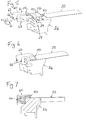
- Figure 1 illustrates a shoe press of conventional form wherein a backing roll 10, mounted to a press frame (not shown) is opposed to a shoe 12.
- the shoe 12 has a concave surface which conforms to the cylindrical surface of the roll 10 and provides an extended nip therebetween.
- an extended nip is advantageous to speed high pressure water removal in paper making machinery.
- a paper web 14 supported upon a felt 16 passes through the nip.
- the shoe 12 is urged towards the backing roll 10 by one or more pistons 18, mounted on a stationary support beam 20.
- a blanket 22 in the form of a seamless tube is mounted over the shoe 12, between said shoe and the paper web supported on the felt 16. Throughout the length of the shoe 12, the blanket 22 has a dimpled configuration, as shown in Fig. 1, but at its end margins, outwards of the shoe 12, it resumes a cylindrical configuration.
- the blanket 22 extends between and is mounted at its respective ends to the rotatable outer portions (usually termed outer heads) of respective front and back heads.
- the outer heads in the shoe press of the invention are preferably provided as continuous rings. In Figures 2 to 7 only a small part-annular portion of one outer head 24 is shown, in each case, together with only a small, part-cylindrical portion of the end margin of the blanket 22.
- the outer head 24 in all of figures 2 to 7 of the drawings is mounted on a bearing (not shown) to allow rotation of the blanket 22.
- the inner surface of the blanket 22 is, in use, lubricated with oil to reduce friction as it passes at high speed (in the region of 15m/sec) over the shoe 12.
- oil to reduce friction as it passes at high speed (in the region of 15m/sec) over the shoe 12.
- the blanket 22 to be sealingly connected to the respective heads. This is possible using, the clamping arrangement of the invention.
- the clamping arrangement of the invention may be used solely for connection to one or each head with addition sealing means also being provided.
- a first preferred practical embodiment of the blanket clamping arrangement of the invention additionally comprises six part-annular wedge segments or inner clamps 30, only one of which is shown, and clamping means in the form of twelve part-annular or segmental outer clamps 40.
- the outer surface of the head 24 is formed with a tapered frustoconical portion 26 and the end surface of the head 24 remote from the blanket 22 is provided with a circular groove 28.
- the wedge segments 30 directly overlie outer surface of the head 24 and are of a size to abut each other circumferentially to form a complete ring encircling the head 24.
- Each wedge segment 30 has an inclined surface portion 32 on its inner surface to mate up with the frustoconical portion 26 of the head 24. Also, in its outer surface each wedge segment 30 has a shallow recess 34 to facilitate release of the blanket 22 when the latter needs replacement.
- the twelve outer clamps 40 are also each of a size to abut each other circumferentially and together provide a complete ring. Alternate clamps 40 in this arrangement are mounted, respectively, so as to completely overlie a central portion of one wedge segment 30 and so as to overlie symmetrically the joint between adjacent wedge segments 30. Also, each is mounted onto the head 24 by means of two bolts 46, as shown.
- the outer clamps 40 are generally U-shaped in section, having an outer limb 41, a central web 42, and an inner limb 43. In use the outer limb 41 extends radially outwards of the wedge segments 30 and clamps the blanket 22 therebetween.
- the central web 42 extends axially outwards of the wedge segments 30 and the head 24 and has apertures 44 through which the bolts 46 extend to connect the outer clamp 40 to the head 24.
- the inner limb 43 projects into the groove 28 and thereby locates the outer clamp 40 relative to the head 24.
- the blanket 22 is a seamless tube and relatively inflexible, and because the heads are not readily demountable from the press frame and have only a limited range of axial adjustment, the blanket 22 has to be installed by passing it over one of the heads.
- the blanket 22 is passed over the front head and positioned relative to the back head as shown.
- the front head is preferably of exactly the same configuration as the back head.
- the taper portion 26 on the front head facilitates feeding the blanket 22 thereover.
- the wedge segments 30 are then positioned as shown, from outside the blanket loop, fitting over the taper portion 26 of the head 24 in the resulting recess below the edge of the blanket 22.
- the outer clamps 40 are then fitted, as shown with their outer limbs 41 overlying the edge of the blanket 22, and bolted onto the head 24. As the bolts 46 are tightened, the outer clamps 40 push the wedge segments 30 up the taper portion 26 of the head 24 moving them both axially and radially so as to clamp and seal the blanket edge between the outer limbs 41 and the wedge segments 30.
- the surfaces of the wedge segments 30 and/or the limbs 41 contacting the blanket edge may be provided with teeth or barbs to increase friction between them and the blanket edge. It will be noted that the blanket edge maintains a substantially straight course between the inner and outer clamps 30, 40.
- a second practical embodiment of the blanket clamping arrangement ofthe invention similarly comprises eight part-annular wedge segments or inner clamps 50 and four part-annular outer clamps 60, arranged exactly as already described in relation to the first embodiment to form two complete rings of abutting components.
- the outer surface of the head 24 is cylindrical (ie in contrast to the first embodiment it does not have a frustoconical taper), but it is formed with an annular groove 29. Its end surface, remote from the blanket 22 is again formed with a circular groove 28.
- Each wedge segment 50 has an inclined surface portion 52 on its outer surface to mate up with a corresponding tapered surface portion 65 on the outer limb 61 of the outer clamp 60.
- the outer clamps 60 are the same as those of the first embodiments having a U-shape in section including a web 62 provided with apertures 64 for bolts 66 and an inner limb 63 to locate into the groove 28.
- Each wedge segment 50 is also formed on its inner surface with a lip 53, a shallow recess 54 and a projection 55.
- the blanket 22 is passed over the front head as previously described, and positioned relative to the outer head 24, as shown in Figs. 5 to 7.
- its edge margin lies directly upon the cylindrical surface of the head.
- the blanket edge is maintained substantially straight.
- the wedge segments 50 are then fitted thereover, with their projections 55 engaging in the groove 29 in the head.
- the outer clamps 60 are then fitted as shown so that their tapered portions 65 overlie the inclined positions 52 of the wedge segments.
- the bolts 66 are tightened the tapered portions 65 ride over the inclined portion 52. This displaces the lip 53 of the wedge segment 50 radially inwards thereby securely clamping and sealing the blanket 22 between the wedge segments 50 and the head 24.
- each segment 50 The purpose of the recess 54 in the inner surface of each segment 50 is to allow bending of the wedge segment as well as to form the lip 53.
- Teeth or barbs may be provided on the inner surface of the inner clamps (wedge segments) 50, i.e. on the lips 53, to improve the gripping force on the blanket edge.
Landscapes
- Paper (AREA)
Priority Applications (1)
| Application Number | Priority Date | Filing Date | Title |
|---|---|---|---|
| EP02251668A EP1342836A1 (de) | 2002-03-08 | 2002-03-08 | Mantelklemmanordnung für eine Schuhpresse einer Papiermaschine |
Applications Claiming Priority (1)
| Application Number | Priority Date | Filing Date | Title |
|---|---|---|---|
| EP02251668A EP1342836A1 (de) | 2002-03-08 | 2002-03-08 | Mantelklemmanordnung für eine Schuhpresse einer Papiermaschine |
Publications (1)
| Publication Number | Publication Date |
|---|---|
| EP1342836A1 true EP1342836A1 (de) | 2003-09-10 |
Family
ID=27741237
Family Applications (1)
| Application Number | Title | Priority Date | Filing Date |
|---|---|---|---|
| EP02251668A Withdrawn EP1342836A1 (de) | 2002-03-08 | 2002-03-08 | Mantelklemmanordnung für eine Schuhpresse einer Papiermaschine |
Country Status (1)
| Country | Link |
|---|---|
| EP (1) | EP1342836A1 (de) |
Citations (3)
| Publication number | Priority date | Publication date | Assignee | Title |
|---|---|---|---|---|
| EP0442257A1 (de) * | 1990-01-16 | 1991-08-21 | Valmet Paper Machinery Inc. | Presswalze |
| DE29702362U1 (de) * | 1996-04-29 | 1997-05-15 | Voith Sulzer Papiermaschinen GmbH, 89522 Heidenheim | Preßwalze |
| US5700357A (en) * | 1996-10-16 | 1997-12-23 | Beloit Technologies, Inc. | Mechanical blanket clamp in rotating head assembly |
-
2002
- 2002-03-08 EP EP02251668A patent/EP1342836A1/de not_active Withdrawn
Patent Citations (3)
| Publication number | Priority date | Publication date | Assignee | Title |
|---|---|---|---|---|
| EP0442257A1 (de) * | 1990-01-16 | 1991-08-21 | Valmet Paper Machinery Inc. | Presswalze |
| DE29702362U1 (de) * | 1996-04-29 | 1997-05-15 | Voith Sulzer Papiermaschinen GmbH, 89522 Heidenheim | Preßwalze |
| US5700357A (en) * | 1996-10-16 | 1997-12-23 | Beloit Technologies, Inc. | Mechanical blanket clamp in rotating head assembly |
Similar Documents
| Publication | Publication Date | Title |
|---|---|---|
| FI87094B (fi) | Pressvals foer behandling av en bandformig produkt. | |
| US4625376A (en) | Press roll for web material with clamped press jacket | |
| CN1024287C (zh) | 压榨辊 | |
| JPS599764B2 (ja) | ウェブ拡張用ロ−ル | |
| US5700357A (en) | Mechanical blanket clamp in rotating head assembly | |
| SE8401741D0 (sv) | Bandpressenhet, foretredesvis som vatpress vid en pappersmaskin | |
| US5951824A (en) | Compliant hydrodynamic/hydrostatic shoe for papermaking press | |
| EP0480968B1 (de) | Geschlossene presseinrichtung mit verlängerter presszone | |
| WO1992008002A1 (en) | An extended nip press apparatus | |
| US7074303B2 (en) | Blanket clamping arrangement for shoe press of papermaking machine | |
| US5556514A (en) | Extended nip press apparatus with geared blanket edge clamp | |
| JPH07113420B2 (ja) | 回転装置のための多分割シ−ルリング | |
| CN1222660C (zh) | 用于锚定压榨带外围边缘的锚式装置 | |
| US7094191B2 (en) | Press roll | |
| JP2880482B2 (ja) | プレスロール | |
| CA2294801C (en) | Edge ring for a press roll | |
| WO1999061700A1 (en) | Arrangement for fastening press jacket to press roll end | |
| JPH1085809A (ja) | 圧延機における密封形ころ軸受 | |
| JP2001213555A (ja) | エキスパンダロール | |
| US5529319A (en) | V-notch seal for non-flooded zone of disc filter valve | |
| JP2006071058A (ja) | 密封装置 | |
| JP2002031127A (ja) | ブランケット装着構造 | |
| ATE343015T1 (de) | Langspalt-walzenpresse zum entwässern einer faserstoffbahn |
Legal Events
| Date | Code | Title | Description |
|---|---|---|---|
| PUAI | Public reference made under article 153(3) epc to a published international application that has entered the european phase |
Free format text: ORIGINAL CODE: 0009012 |
|
| AK | Designated contracting states |
Kind code of ref document: A1 Designated state(s): AT BE CH CY DE DK ES FI FR GB GR IE IT LI LU MC NL PT SE TR |
|
| AX | Request for extension of the european patent |
Extension state: AL LT LV MK RO SI |
|
| 17P | Request for examination filed |
Effective date: 20031220 |
|
| AKX | Designation fees paid |
Designated state(s): AT BE CH CY DE DK ES FI FR GB GR IE IT LI LU MC NL PT SE TR |
|
| 17Q | First examination report despatched |
Effective date: 20040917 |
|
| STAA | Information on the status of an ep patent application or granted ep patent |
Free format text: STATUS: THE APPLICATION IS DEEMED TO BE WITHDRAWN |
|
| 18D | Application deemed to be withdrawn |
Effective date: 20050128 |