EP1342842A2 - Racle pour enlever l' eau - Google Patents
Racle pour enlever l' eau Download PDFInfo
- Publication number
- EP1342842A2 EP1342842A2 EP03251396A EP03251396A EP1342842A2 EP 1342842 A2 EP1342842 A2 EP 1342842A2 EP 03251396 A EP03251396 A EP 03251396A EP 03251396 A EP03251396 A EP 03251396A EP 1342842 A2 EP1342842 A2 EP 1342842A2
- Authority
- EP
- European Patent Office
- Prior art keywords
- fibers
- doctor blade
- mating member
- fibrous
- belt
- Prior art date
- Legal status (The legal status is an assumption and is not a legal conclusion. Google has not performed a legal analysis and makes no representation as to the accuracy of the status listed.)
- Withdrawn
Links
Images


Classifications
-
- D—TEXTILES; PAPER
- D21—PAPER-MAKING; PRODUCTION OF CELLULOSE
- D21F—PAPER-MAKING MACHINES; METHODS OF PRODUCING PAPER THEREON
- D21F3/00—Press section of machines for making continuous webs of paper
- D21F3/02—Wet presses
- D21F3/0209—Wet presses with extended press nip
- D21F3/0218—Shoe presses
- D21F3/0227—Belts or sleeves therefor
-
- D—TEXTILES; PAPER
- D21—PAPER-MAKING; PRODUCTION OF CELLULOSE
- D21G—CALENDERS; ACCESSORIES FOR PAPER-MAKING MACHINES
- D21G3/00—Doctors
- D21G3/005—Doctor knifes
-
- Y—GENERAL TAGGING OF NEW TECHNOLOGICAL DEVELOPMENTS; GENERAL TAGGING OF CROSS-SECTIONAL TECHNOLOGIES SPANNING OVER SEVERAL SECTIONS OF THE IPC; TECHNICAL SUBJECTS COVERED BY FORMER USPC CROSS-REFERENCE ART COLLECTIONS [XRACs] AND DIGESTS
- Y10—TECHNICAL SUBJECTS COVERED BY FORMER USPC
- Y10T—TECHNICAL SUBJECTS COVERED BY FORMER US CLASSIFICATION
- Y10T428/00—Stock material or miscellaneous articles
- Y10T428/24—Structurally defined web or sheet [e.g., overall dimension, etc.]
- Y10T428/24132—Structurally defined web or sheet [e.g., overall dimension, etc.] including grain, strips, or filamentary elements in different layers or components parallel
Definitions
- This invention relates to doctor blades, and particularly to a doctor blade suitable for removing water from an elastic belt in the press part of a papermaking machine.
- a pair of felts F, and an air-impermeable, endless, elastic belt B are pinched in a nip N formed by a press roll P and a shoe S.
- the press roll P rotates in the direction of arrow P'
- the elastic belt B also rotates in the direction of arrow B', and, as a wet paper web W passes through the press part it is pinched by felts F, and water is squeezed from it. Oil is supplied to the inside of the elastic belt B to reduce friction between the belt and the shoe S.
- the surface of the shoe S which is opposed to the press roll P conforms to the shape of the outer surface of the press roll. Therefore, the area of the nip can be much larger than the corresponding area in a press apparatus comprising a pair of press rolls (not shown), and a greater water squeezing effect can be achieved. Therefore, the shoe press apparatus has an important advantage in that much less heat is needed for drying the wet paper web W after water is squeezed from it, and accordingly a significant saving in fuel or energy cost can be realized.
- the belt comprises a base member b, and high molecular weight elastic members e on both sides of the base member.
- the base member b which is preferably a woven fabric having a warp and weft, is provided to impart strength to the elastic belt B as a whole.
- the high molecular weight elastic members e are preferably composed of resin such as a urethane resin, having a Shore hardness A of 70 to 98 degrees.
- the felt contacting surface and the shoe contacting surface of the elastic belt are both composed of such resins.
- a plurality of grooves may be formed on the felt-contacting surface of the elastic belt B, so that the water squeezed from the wet paper web W may be held in the grooves.
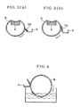
- Compressed air may be supplied to the inside of an elastic belt B to expand the belt to the shape as shown in FIG. 6.
- part of the water squeezed from the wet paper web W moves to the elastic belt B through the felt F which moves between the web W and the belt B.
- most of the water which moves through the felt F to the belt B is shaken off in the direction of arrow a in FIG. 6 as a result of the movement of the belt, part of the water will continue to adhere to the elastic belt B and reenter the nip.
- the water squeezing effect of the press part may not be adequate.
- a doctor blade similar to the doctor blade used to remove water from a press roll, might be brought into contact with the elastic belt B to remove water from the belt.
- Doctor blades used in with press rolls include metallic doctor blades, and doctor blades composed of a felt impregnated with a wear-resistant rubber, synthetic resin or the like, as disclosed in Unexamined Japanese Patent Publication No. 20697/1981. Although such doctor blades are effective to remove excess water from a press roll, problems are encountered in attempts to use such doctor blades to remove water from elastic belts.
- a metallic doctor blade can efficiently remove water from an elastic belt, but causes the elastic belt to wear out rapidly. There is also a risk of damage caused by digging of the tip of the metallic doctor blade into the belt. Moreover, the expansion of the elastic belt by compressed air results in a bulging of the belt, such that its outer surface departs from a cylindrical shape. Accordingly, the outer surface of the belt is not necessarily straight in the cross machine direction, and it is difficult to make a metallic doctor blade contact the surface of the belt uniformly.
- a doctor blade composed of a felt impregnated with a wear-resistant synthetic resin exhibits excellent adhesion to the surface of an elastic belt, and may have an effect of removing water on the surface of an elastic belt.
- a resin-impregnated felt doctor blade is used with an elastic belt having grooves, water in the grooves may not be adequately removed because the fibers of the doctor blade may adequately get into the grooves of the belt.
- a doctor blade comprising a fibrous lamination impregnated with resin, is in contact with a mating member movable relative to the doctor blade for removing water from the mating member.
- the fibrous lamination comprises a fibrous contacting layer in contact with the mating member, and at least one layer in addition to the fibrous contacting layer, said at least one layer being out of contact with the mating member. Fibers in the fibrous contacting layer are oriented substantially in the direction of movement of the mating member relative to said contacting layer, preferably within 15 degrees relative to the direction of movement of the mating member.
- the diameters of the fibers of the fibrous contacting layer are larger than the diameters of the fibers of the at least one layer that is out of contact with the mating member.
- the resin impregnation rate in the fibrous contacting layer is also preferably less than the resin impregnation rate of the at least one layer that is out of contact with the mating member.
- the doctor blade for removing water according to the invention has a greater adhesion to a mating member, due to the fiber orientation in the mating member-contacting layer.
- frictional force is exerted in a direction parallel to the axial direction of the fibers, friction with the mating member is reduced, abrasion of the fibers of the doctor blade decreases and the durability of the doctor blade is improved.
- the orientation of the fibers at the contacting surface of the doctor blade allows more fibers to enter the grooves of the belt, and consequently, water in the grooves is removed more efficiently.
- the fibers of the mating member-contacting layer are oriented substantially in one direction when laid out during the formation of the layer. This one direction will be the same direction in which the mating member moves relative to the doctor blade. When the mating member makes a rotating movement rather than a planar movement, the direction of movement will be considered in the tangential direction.
- the fibers have windings to some extent due possibly to crimp, they may be considered to be oriented substantially in the direction of movement of the mating member when viewed as a whole. Also, even if they have windings in the thickness direction due possibly to needling, etc., they may be regarded to be oriented substantially in the direction of movement of the mating member when viewed perpendicularly with respect to a plane extending along the direction of movement of the mating member.
- FIG. 1(a) is a cross-sectional view of a laminated doctor blade for according to the invention
- FIG. 1(b) is a cross-sectional view illustrating one shape of a doctor blade in accordance with the invention
- FIG. 1(c) is a cross-sectional view illustrating another shape of a doctor blade in accordance with the invention.
- FIG. 2(a) is a top plan view illustrating the formation of a fibrous lamination in accordance with the invention, using a cross lapper wherein, after a web is opened by carding, it is laminated on a conveyer;
- FIG. 2(b) is an explanatory plan view showing that there are two directions of orientation of fibers in a fibrous lamination
- FIG. 3(a) is a schematic view showing a doctor blade of FIG. 1(b) used in a shoe press apparatus, where only the tip of the doctor blade is in a pressing contact with an elastic belt;
- FIG. 3(b) is an schematic view, similar to FIG. 3(a), but showing the doctor blade in a deformed condition, with a part of one of its faces in pressing contact with an elastic belt;
- FIG. 4 is a schematic view of an apparatus for conducting water removal and endurance testing of doctor blades
- FIG. 5(a) is a table showing the results of water removal capability and endurance tests of doctor blades in accordance with the invention and comparing those results with results of corresponding tests carried out on comparative examples;
- FIG. 5(b) is a schematic cross-sectional view illustrating partial resin impregnation in a laminate in accordance with the invention.
- FIG. 6 is a schematic, cross-sectional view of a shoe press apparatus used in the press part of a papermaking machine
- FIG. 7 is an enlarged cross-sectional view of a grooved elastic belt used in a shoe press apparatus.
- FIG. 8(a) is an enlarged cross-sectional view showing the relationship between randomly oriented fibers of a doctor blade in accordance with a comparative example and the grooves of an elastic belt;
- FIG. 8(b) is an enlarged cross-sectional view showing the relationship between the grooves of an elastic belt and fibers of a doctor blade in accordance with the invention, wherein the fibers are oriented in the direction of the elongation of the grooves.
- the doctor blade according to the invention is made by impregnating a fibrous lamination 50 with resin.
- the lamination 50 comprises base material layers 20 and batt fiber layers 30.
- the base material layers 20 will usually be woven fabric layers formed from yarns of general-purpose fibers, film, spun bond or molded resin materials may be used as the base material layers.
- the batt fiber layers 30 are made by layering general-purpose fibers.
- the lamination 50 is made by laminating and integrating a plurality of base material layers 20 and a plurality of fibrous layers 30 together. In some circumstances, the base material layers 20 can be omitted, so that the lamination 50 is composed only of fibrous layers 30.
- the fibers are oriented, for example by carding, in the direction of travel of the mating member.
- adhesion of the doctor blade to the mating member is improved, and a large number of fibers enter the grooves of the mating member so that water in the grooves is removed.
- abrasion due to fibers in the doctor blade is at the minimum when fibers are rubbed in the axial direction. Therefore, if the orientation of fibers is in parallel with the direction of travel of the mating member, the wear and tear of the doctor blade due to abrasion can be prevented, and the service life of the doctor blade can be extended.
- One method for adjusting the orientation of fibers in a fibrous layer is to form a fibrous layer by laminating a web which is oriented in one direction by carding.
- Another method, as shown in FIG. 2 is to utilize webs C, which are oriented in one direction by carding, and to laminate the webs alternately at an angle by a cross lapper. It is preferable that the orientation angle D of the fibers be within 15 degrees relative to the direction of travel of the mating member.
- a fibrous laminate 30 in which the layers are integrated by needling, at least the layer which comes into contact with a mating member is a fibrous layer wherein the fibers are oriented in the direction of travel of the mating member.
- the fibers in the other layers need not be oriented in the direction of travel of the mating member, and can have any desired orientation, even random orientation.
- the base material layers and fibrous layers can be first laminated and then intertwined by needle punching.
- groups of layers may be intertwined preliminarily by needle punching, and thereafter the groups of layers may be intertwined by another needle punching operation to form the laminate.
- the base material layers 20 and the fibrous layers 30 may be glued together by resin, etc.
- intertwining integration by needle punching has the advantage of suppressing peeling of the layers.
- a binder comprising a high molecular weight compound may be added by sprinkling when heat meltable fibers are mixed with a fibrous layer 30, or when a fibrous layer is integrated with a base material layer by needling etc.
- a binder comprising a high molecular weight compound may be added by sprinkling after the layers are integrated, and the layers may be subjected to heating before being impregnated with a resin solution.
- the resin solution is preferably one in which a hardener, additive, and a thickener such as a methylcellulose, are mixed or scattered in thermoplastic or thermosetting resin or a mixture thereof.
- the resin may be, for example, SBR (styrene butadiene copolymer synthetic rubber), polyurethane resin, acrylic resin, epoxy resin, or phenol resin.
- the impregnation level of resin in the laminate 50 may be controlled by increasing or decreasing the amount of thickener is mixed into the resin solution. In selecting the resin, abrasion resistance and resistance to hydrolysis are considered. A single kind of resin, or a mixture composed of several kinds of resin, may be used.
- the laminate 50 After the laminate 50 is impregnated with resin solution, it is heated to harden the resin, and cut so that the fibers of the layer which comes into contact with a mating member are oriented in the direction of travel of the mating member. If necessary, a taper is formed by machining, and a doctor blade 10b or 10c, having the shape shown in FIG. 1(b) or FIG. 1(c), may be obtained.
- the orientations of fibers of the fibrous layers vary.
- the fibers of the layer which comes into contact with a mating member are oriented in the direction of travel of the mating member, whereas the fibers at the other surface may have a different orientation.
- each of the doctor blades 10b and 10c comprises two layers of fiber having different orientations
- fibers may be more effectively prevented from falling off due to improved intertwinement when the fibers are integrated by needling.
- mating member contacting layers 14b and 14c the layers wherein fibers are oriented in the direction of travel of a mating member under the surface 12b or 12c are referred to as mating member contacting layers 14b and 14c.
- the upper and lower sides of the doctor blade shown in FIG. 1(b) may be reversed.
- the part having a protrusion formed as a result of tapering is the mating member contacting layer.
- the resin may be impregnated into the laminate 50 by a method wherein fine particles of resin are impregnated into the surface of the laminate, and heated and pressurized using a press. Similar resins can be used in either case, and abrasion resistance and flexibility should be taken into account in both cases.
- the void content of the doctor blade 10 may be controlled by selecting the density of the laminate 50 or the amount of impregnated resin.
- the void content may also be controlled by adding a foaming agent to the above-mentioned resin solution or fine resin particles.
- Frictional drag of the doctor blade against an elastic belt B may be decreased by including an additive which has lubricity, such as molybdenum disulfide, in the resin solution or fine resin particles.
- an additive which has lubricity such as molybdenum disulfide
- the belt has a superior ability to remove water from the belt due to the high rigidity of the fibers in the belt-contacting layer.
- the surface properties of a doctor blade are inferior, and adhesion of the blade to the elastic belt is decreased. Superior effects may be obtained by mixing thin fibers into the thick fibers.
- FIGs. 3(a) and 3(b) show the doctor blade 10b of FIG. 1(b) used in a shoe press apparatus. (The press roller is not shown).
- the doctor blade 10b may be used either with only its tip pressing against the mating belt B as shown in FIG. 3(a), or with part of its surface 12b pressing against the belt as shown in FIG. 3(b). In either case, a mating member contacting layer 14b of the doctor blade 10b is in contact with the elastic belt B.
- the doctor blade 10b is used as shown in FIG. 3(b), the area of the blade which is in contact with the belt B is broader.
- the water which is removed by the doctor blade 10b is made to flow to a water receiver R.
- Example 1 a woven fabric of plain weave having spun polyester (PET) yarn as its warp and weft, and a basis weight of 100 g/m 2 , was used as a base material, and polyester fiber (17 dtex) was used for the fibrous batt layers. Fibers oriented in one direction by carding were used for all the layers.
- PET spun polyester
- Polyester fibrous batt layers were provided on both sides of the base material, and integrated with the base material by needling.
- the amount of the polyester fiber in each fibrous batt layer was 120 g/m 2 .
- Example 3 a woven fabric of plain weave having spun polyester (PET) yarn as warp and weft (basis weight 100 g/m 2 ) was used for a base material and 17 dtex polyester fiber was used for the fibrous batt layers. Fibrous layer oriented in one direction by carding were used for seven layers on the top side of the blade, which was in contact with a mating member. Fibrous layers of different orientation were used for other layers.
- PET spun polyester
- weft basic weight 100 g/m 2
- the polyester fibrous layers were integrated with the base material by needling, and fibrous layers were provided on both sides of the each layer of base material.
- the amount of the polyester fiber in each layer was 120 g/m 2 .
- Example 4 a woven fabric of plain weave having spun polyester (PET) yarn as warp and weft (basis weight 100 g/m 2 ) was used for a base material, and 40 dtex polyester fiber was used for seven batt fiber layers on the top side which was in contact with a mating member. Fibrous layers of different orientation comprising 17 dtex polyester fibers were used for other layers.
- PET spun polyester
- the polyester fibrous layers were integrated with the base material by needling, and the fibrous layers were provided on both sides of each layer of base material.
- the amount of polyester fiber in each layer was 120 g/m 2 .
- polyester fiber 120 g/m 2 was integrated by needling so that the fibers of the seven fibrous layers on the side which was in contact with the mating member were oriented in the direction of travel of the mating member.
- a laminate having an areal weight (Metsuke) of 3500 g/m 2 and a thickness of 10 mm as a whole was obtained.
- the density of this lamination was 0.35 g/cm 3 .
- Example 5 woven fabric of plain weave having spun polyester yarn (PET) as warp and weft (basis weight 100 g/m 2 ) was used for a base material.
- Fibrous batt layers were composed of 40 dtex polyester fiber and 17 dtex polyester fiber, mixed at a weight ratio of 1:1. These fibers were oriented in one direction by carding and used for seven layers on the top side of the blade, which was in contact with a mating member. Fibrous layers of different orientation, comprising 17dtex polyester fibers were used as other layers.
- the polyester fibrous layers were integrated with the base material by needling, and fibrous layers were provided on both sides of each layer of base material.
- the amount of the polyester fiber in each layer was 120 g/m 2 .
- the base material was a woven fabric of plain weave composed of spun polyester (PET) yarn as warp and weft, having a basis weight 100 g/m 2 . Fibrous layers of 17 dtex polyester fiber oriented in random directions by carding were used for all the layers.
- PET spun polyester
- the polyester fibrous layers were integrated with the base material by needling, and fibrous layers were provided on both sides of each layer of base material.
- the amount of the polyester fiber in each layer was 120 g/m 2 .
- a resin solution was prepared by adding a thickener to a solution comprising styrene butadiene latex (SBR) and a hardener. These components were mixed and diluted with water. This resin solution was applied to the one side of the above-described laminate.
- SBR styrene butadiene latex
- a doctor blade of Comparative example 2 and doctor blade of Example 2 according to the invention were different from others in that the depth T, as shown in FIG. 5(b), to which the resin solution was impregnated into the laminate was 5 mm in the direction of thickness.
- the resin was dried and hardened, and cutting was conducted so that the fibers of the layer which contacts a mating member were oriented in the direction of travel of the mating member. Then, a taper, as shown in FIG. 1(b), was formed by machining, and a doctor blade having a resin impregnation rate (the weight ratio of solid resin to the laminate) of 20% was obtained.
- the belt B in the test apparatus was rotated at 60 rpm for five minutes.
- the amount of water removed by the doctor blade that is, the amount of water collected in a water receiver R during that five minute interval, was measured.
- the durability of the doctor blade was measured by rotating the belt B at 100 rpm for 1000 hours in the same apparatus.
- the results of the water removal capability test and the endurance test are shown by ratio in FIG. 5.
- a large value in the water removal capability test results corresponds to a high water removal capability.
- a large value in the endurance test results corresponds a high durability, that is, a low abrasion loss, in the doctor blade.
- the doctor blades of Examples 1-5 according to the invention exhibit superior water removal capability and durability compared to the water removal capability and durability of Comparative examples 1 and 2.
- FIGs. 8(a) and 8(b) depict the manner in which the fibers of a doctor blade enter the grooves of a mating member.
- the doctor blade is in accordance with Comparative examples 1 and 2, in which the fibers which are in contact with the mating member are oriented in random directions.
- FIG. 8(b) shows a doctor blade according to the invention, in which the fibers which are in contact with a mating member are oriented along the grooves.
- the amount of fiber which enters the grooves is larger in the case of FIG. 8(b) than in the case of FIG. 8(a), and relatively larger amount of water in the grooves are removed in the case of FIG. 8(b).
- Fig. 8(b) in effect represents a situation in which the semi-circular shapes in Fig. 8(a) are revolved about 90 degrees.
- the mating member from which water is to be removed is not necessarily limited to the elastic belt of a shoe press apparatus.
- a doctor blade according to the invention exhibits a greater adhesion to the mating member as a result of the orientation of its surface fibers.
- frictional force is applied in a direction parallel to the axial direction of the fiber friction with the mating member is reduced, and abrasion of the fibers of the doctor blade decreases, with the result that the durability of the doctor blade is improved.
- the mating member is an elastic belt having grooves
- the invention allows a greater number of fibers of the doctor blade to enter the grooves for more efficient removal of water.
Landscapes
- Paper (AREA)
Applications Claiming Priority (2)
| Application Number | Priority Date | Filing Date | Title |
|---|---|---|---|
| JP2002063928 | 2002-03-08 | ||
| JP2002063928 | 2002-03-08 |
Publications (2)
| Publication Number | Publication Date |
|---|---|
| EP1342842A2 true EP1342842A2 (fr) | 2003-09-10 |
| EP1342842A3 EP1342842A3 (fr) | 2004-11-17 |
Family
ID=27751257
Family Applications (1)
| Application Number | Title | Priority Date | Filing Date |
|---|---|---|---|
| EP03251396A Withdrawn EP1342842A3 (fr) | 2002-03-08 | 2003-03-07 | Racle pour enlever l' eau |
Country Status (3)
| Country | Link |
|---|---|
| US (1) | US6979387B2 (fr) |
| EP (1) | EP1342842A3 (fr) |
| CN (1) | CN1289753C (fr) |
Cited By (1)
| Publication number | Priority date | Publication date | Assignee | Title |
|---|---|---|---|---|
| EP2455165A1 (fr) * | 2010-11-18 | 2012-05-23 | Exel Composites OYJ | Procédé de fabrication d'un stratifié de lame de docteur et stratifié de lame de docteur |
Families Citing this family (8)
| Publication number | Priority date | Publication date | Assignee | Title |
|---|---|---|---|---|
| MXPA06014520A (es) * | 2004-06-14 | 2007-03-23 | Kadant Web Systems Inc | Elementos planos para utilizarse en maquinas de fabricacion de papel. |
| US8193606B2 (en) | 2005-02-28 | 2012-06-05 | Semiconductor Energy Laboratory Co., Ltd. | Semiconductor device including a memory element |
| CN101263261A (zh) * | 2005-09-08 | 2008-09-10 | 卡当特网络系统股份有限公司 | 在造纸装置中使用的结合了玄武岩纤维的平面元件 |
| US7605410B2 (en) * | 2006-02-23 | 2009-10-20 | Semiconductor Energy Laboratory Co., Ltd. | Semiconductor device and manufacturing method thereof |
| WO2008025172A1 (fr) * | 2006-08-29 | 2008-03-06 | Daetwyler Swiss Tec Ag | Lame de docteur |
| WO2009100344A2 (fr) * | 2008-02-08 | 2009-08-13 | Kadant Web Systems, Inc. | Surfaces thermiquement adaptatives pour recevoir des pulvérisations thermiques |
| FI120459B (fi) * | 2008-03-06 | 2009-10-30 | Metso Paper Inc | Kaavinterä ja menetelmä kaavinterän valmistamiseksi |
| US11098450B2 (en) | 2017-10-27 | 2021-08-24 | Albany International Corp. | Methods for making improved cellulosic products using novel press felts and products made therefrom |
Family Cites Families (4)
| Publication number | Priority date | Publication date | Assignee | Title |
|---|---|---|---|---|
| GB753846A (en) * | 1954-01-12 | 1956-08-01 | Harold Eric Baliol Scott | Doctors for papermaking and like machines |
| JPS5620697A (en) | 1979-07-24 | 1981-02-26 | Ichikawa Woolen Textile | Felt for doctor blade |
| US4549933A (en) * | 1983-07-05 | 1985-10-29 | Thermo Electron Corporation | Doctor blade with non-homogeneous stiffness properties |
| US6643890B2 (en) * | 2000-12-01 | 2003-11-11 | S. D. Warren Services Company | Composite doctor blades |
-
2003
- 2003-03-06 US US10/383,205 patent/US6979387B2/en not_active Expired - Fee Related
- 2003-03-07 CN CNB031071333A patent/CN1289753C/zh not_active Expired - Fee Related
- 2003-03-07 EP EP03251396A patent/EP1342842A3/fr not_active Withdrawn
Cited By (1)
| Publication number | Priority date | Publication date | Assignee | Title |
|---|---|---|---|---|
| EP2455165A1 (fr) * | 2010-11-18 | 2012-05-23 | Exel Composites OYJ | Procédé de fabrication d'un stratifié de lame de docteur et stratifié de lame de docteur |
Also Published As
| Publication number | Publication date |
|---|---|
| US20030168196A1 (en) | 2003-09-11 |
| CN1443897A (zh) | 2003-09-24 |
| CN1289753C (zh) | 2006-12-13 |
| US6979387B2 (en) | 2005-12-27 |
| EP1342842A3 (fr) | 2004-11-17 |
Similar Documents
| Publication | Publication Date | Title |
|---|---|---|
| EP2508674A2 (fr) | Feutre de presse | |
| US6979387B2 (en) | Doctor blade for removing water | |
| KR20060071332A (ko) | 초지반송펠트 및 상기 초지반송펠트를 구비한 초지기의프레스 장치 | |
| US5753085A (en) | Textile substrate for a long nip press belt | |
| EP1295988B1 (fr) | Racle | |
| US7105077B2 (en) | Press felt for papermaking and manufacturing method | |
| US6929718B2 (en) | Shoe press belt | |
| KR20040083359A (ko) | 습지반송용 벨트 | |
| US6969691B2 (en) | Doctor blade for removing water | |
| EP0937177B1 (fr) | Habillage pour machine a papier | |
| US7175742B2 (en) | Doctor blade | |
| JPH0229793B2 (fr) | ||
| US20070240844A1 (en) | Paper Transporting Felt and Press Apparatus of Paper Machine Having the Paper Transporting Felt | |
| KR20060055396A (ko) | 초지반송펠트 및 상기 초지반송펠트를 구비한 초지기의프레스 장치 | |
| JP2003328290A (ja) | 水切り用ドクターブレード | |
| JP4958447B2 (ja) | 抄紙搬送フェルト | |
| JP2004197247A (ja) | 製紙用ベルト基礎布並びにそれを用いた製紙用ベルト及びシュープレス用ベルト | |
| EP1797238A1 (fr) | Feutre de transport de papier pour presse à sabot | |
| MXPA99004299A (en) | Papermachine clothing |
Legal Events
| Date | Code | Title | Description |
|---|---|---|---|
| PUAI | Public reference made under article 153(3) epc to a published international application that has entered the european phase |
Free format text: ORIGINAL CODE: 0009012 |
|
| AK | Designated contracting states |
Kind code of ref document: A2 Designated state(s): AT BE BG CH CY CZ DE DK EE ES FI FR GB GR HU IE IT LI LU MC NL PT SE SI SK TR |
|
| AX | Request for extension of the european patent |
Extension state: AL LT LV MK RO |
|
| PUAL | Search report despatched |
Free format text: ORIGINAL CODE: 0009013 |
|
| AK | Designated contracting states |
Kind code of ref document: A3 Designated state(s): AT BE BG CH CY CZ DE DK EE ES FI FR GB GR HU IE IT LI LU MC NL PT SE SI SK TR |
|
| AX | Request for extension of the european patent |
Extension state: AL LT LV MK RO |
|
| 17P | Request for examination filed |
Effective date: 20050303 |
|
| AKX | Designation fees paid |
Designated state(s): DE FI FR IT SE |
|
| STAA | Information on the status of an ep patent application or granted ep patent |
Free format text: STATUS: THE APPLICATION IS DEEMED TO BE WITHDRAWN |
|
| 18D | Application deemed to be withdrawn |
Effective date: 20060612 |