EP1342849A2 - Rouleau de compactage - Google Patents
Rouleau de compactage Download PDFInfo
- Publication number
- EP1342849A2 EP1342849A2 EP03003966A EP03003966A EP1342849A2 EP 1342849 A2 EP1342849 A2 EP 1342849A2 EP 03003966 A EP03003966 A EP 03003966A EP 03003966 A EP03003966 A EP 03003966A EP 1342849 A2 EP1342849 A2 EP 1342849A2
- Authority
- EP
- European Patent Office
- Prior art keywords
- piston
- unbalance
- cylinder
- roller according
- compaction roller
- Prior art date
- Legal status (The legal status is an assumption and is not a legal conclusion. Google has not performed a legal analysis and makes no representation as to the accuracy of the status listed.)
- Granted
Links
- 238000005056 compaction Methods 0.000 title claims description 23
- 239000003921 oil Substances 0.000 claims abstract description 31
- 239000010720 hydraulic oil Substances 0.000 claims abstract description 12
- 230000003247 decreasing effect Effects 0.000 claims abstract description 3
- 230000005284 excitation Effects 0.000 claims description 10
- 238000005096 rolling process Methods 0.000 claims description 5
- 238000005259 measurement Methods 0.000 claims description 4
- 238000013016 damping Methods 0.000 claims description 2
- 238000009434 installation Methods 0.000 claims description 2
- 239000012530 fluid Substances 0.000 claims 1
- 229910001385 heavy metal Inorganic materials 0.000 claims 1
- 239000007788 liquid Substances 0.000 abstract 2
- 230000000638 stimulation Effects 0.000 abstract 2
- 239000010426 asphalt Substances 0.000 description 6
- 239000000463 material Substances 0.000 description 5
- 239000011148 porous material Substances 0.000 description 5
- 230000006835 compression Effects 0.000 description 3
- 238000007906 compression Methods 0.000 description 3
- 238000006073 displacement reaction Methods 0.000 description 3
- 230000000694 effects Effects 0.000 description 3
- 238000009499 grossing Methods 0.000 description 3
- 239000002689 soil Substances 0.000 description 3
- 125000006850 spacer group Chemical group 0.000 description 3
- 230000003068 static effect Effects 0.000 description 3
- 230000035882 stress Effects 0.000 description 3
- 238000001816 cooling Methods 0.000 description 2
- 229910052751 metal Inorganic materials 0.000 description 2
- 241001295925 Gegenes Species 0.000 description 1
- 230000006978 adaptation Effects 0.000 description 1
- 230000032683 aging Effects 0.000 description 1
- 230000000712 assembly Effects 0.000 description 1
- 238000000429 assembly Methods 0.000 description 1
- 238000005452 bending Methods 0.000 description 1
- 230000000903 blocking effect Effects 0.000 description 1
- 238000010276 construction Methods 0.000 description 1
- 239000004035 construction material Substances 0.000 description 1
- 230000001771 impaired effect Effects 0.000 description 1
- 229910052500 inorganic mineral Inorganic materials 0.000 description 1
- 239000002184 metal Substances 0.000 description 1
- 239000011707 mineral Substances 0.000 description 1
- 210000002445 nipple Anatomy 0.000 description 1
- 230000010355 oscillation Effects 0.000 description 1
- 238000005086 pumping Methods 0.000 description 1
- 230000001105 regulatory effect Effects 0.000 description 1
- 238000007789 sealing Methods 0.000 description 1
- 239000000758 substrate Substances 0.000 description 1
- 230000007704 transition Effects 0.000 description 1
- XLYOFNOQVPJJNP-UHFFFAOYSA-N water Substances O XLYOFNOQVPJJNP-UHFFFAOYSA-N 0.000 description 1
Images




Classifications
-
- E—FIXED CONSTRUCTIONS
- E01—CONSTRUCTION OF ROADS, RAILWAYS, OR BRIDGES
- E01C—CONSTRUCTION OF, OR SURFACES FOR, ROADS, SPORTS GROUNDS, OR THE LIKE; MACHINES OR AUXILIARY TOOLS FOR CONSTRUCTION OR REPAIR
- E01C19/00—Machines, tools or auxiliary devices for preparing or distributing paving materials, for working the placed materials, or for forming, consolidating, or finishing the paving
- E01C19/22—Machines, tools or auxiliary devices for preparing or distributing paving materials, for working the placed materials, or for forming, consolidating, or finishing the paving for consolidating or finishing laid-down unset materials
- E01C19/23—Rollers therefor; Such rollers usable also for compacting soil
- E01C19/28—Vibrated rollers or rollers subjected to impacts, e.g. hammering blows
- E01C19/286—Vibration or impact-imparting means; Arrangement, mounting or adjustment thereof; Construction or mounting of the rolling elements, transmission or drive thereto, e.g. to vibrator mounted inside the roll
Definitions
- the invention relates to a compaction roller according to the preamble of claim 1.
- the aim is to compact unbound as well as hydraulically or bituminously bound materials in earthworks or road construction as quickly as possible to the prescribed Proctor or Marshall density, but at the same time to prevent over-compaction and, especially with wear layers, to minimize grain shattering of the mineral components.
- bituminous road surfaces In the case of bituminous road surfaces, a smoothing of the surface during compaction must be avoided in order to either ensure a good layer bond or a good grip with wear layers.
- the setting of optimal system sizes for short compaction times is imperative for bituminous materials, since the material can be compacted by cooling disappears and in the worst case the prescribed final density cannot be achieved.
- compacting drainage asphalt open-pore asphalt
- the pores in the area near the surface must not be closed in order to achieve the desired water drainage and to reduce the so-called "air pumping" effect when car tires roll off in the contact zone between the tire and the road.
- a directional oscillator In the compacting rollers, which are described in DE 4 129 182 A1 and EP 0 954 187 A2, a directional oscillator consists of at least two excitation shafts running in opposite directions, the resulting force of which can be continuously rotated from a horizontal direction in a vertical direction without torque. The nominal amplitude or unbalance is not changed in this system.
- undesirable waves, smoothing and pore closures can occur, particularly in the case of horizontal vibrations.
- a vibration exciter for a soil compacting machine in which an exciter shaft with an unbalance is provided, wherein a cylinder arranged radially to the exciter shaft with a spring-loaded piston is used to automatically adjust the unbalance due to the change in speed to cause changing centrifugal force.
- a cylinder arranged radially to the exciter shaft with a spring-loaded piston is used to automatically adjust the unbalance due to the change in speed to cause changing centrifugal force.
- the object of the invention is to provide a compaction roller according to the preamble of claim 1, which enables an optimal adaptation of the vibration to the respective road construction materials or to local conditions such as bridges and vibration-sensitive structures and facilities.
- an actuating cylinder is provided, the space of the actuating cylinder that communicates with the unbalance cylinder is connected to a hydraulic source for replacing leakage oil via a controllable valve, which in a middle or intermediate position between the two end positions of the unbalance piston, from which the nominal amplitude can be increased or decreased , locks.
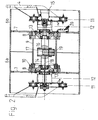
- the tandem compacting roller shown in Fig. 1 comprises a superstructure 1 with a driver's cab, under the front and rear of which a roller body 2 or 3 is mounted on steerable turntable 4. Between the two roller bodies 2, 3 there is an engine compartment 5 which receives a drive engine, usually a diesel engine.
- a drive engine usually a diesel engine.
- the front and / or rear roll body 2, 3 comprises two drum halves 6a, 6b arranged side by side in the axial direction and each have a radially extending drum base 7 with a central passage opening.
- a bearing flange 8 is attached to each of the drum bases 7.
- the two bandage halves 6a, 6b are connected to one another via the two bearing flanges 8 and a spacer tube 9 so as to be rotatable about the roller body axis, in that a bearing 10, for example a roller bearing, is arranged between a bearing flange 8 and the spacer tube 9.
- the turntable 4, which is steerably connected to the superstructure 1, is elastically connected on both sides via damping elements 11, for example rubber-metal elements, and a flange plate 11a, each with a hollow hydraulic drive motor 12.
- the traction motors 12 are connected on the output side to the adjacent bearing flange 8 via a flange 13 and thus drive the bandage halves 6a, 6b in each case.
- an excitation shaft 14 which is driven by a hydraulic vibration motor 15 and is supported by bearings opposite the bearing flanges 8.
- An unbalance cylinder 16 is mounted centrally in a bore in the excitation shaft 14.
- the unbalance cylinder 16 has a corresponding collar and on the opposite side a threaded section for bracing by means of a clamping ring and a pair of nuts.
- the unbalance cylinder 16 accommodates an unbalance piston 17 in a hydraulically adjustable manner radially to the roll body axis.
- the unbalance in the excitation shaft 14, which is sufficient to achieve the smallest nominal amplitude of the roller body, can be added continuously.
- the unbalance piston 17 can be filled with lead in order to achieve the largest possible adjustment range of the nominal amplitude in the smallest installation space.
- the unbalance piston 17 is equipped with guide bands and a piston sealing ring. Deformations of the excitation shaft 14 (bending due to centrifugal forces) are not transmitted to the unbalance cylinder 16 due to sufficient play. The amount of oil required to move the unbalance piston 17 is made available through a bore 18 in the excitation shaft 14. The oil pressure is transmitted to the piston head via a taper of the unbalance piston 17 and bores 19.
- bearing flanges 8 there is an oil inlet and outlet nipple 20 in order to lubricate the space inside the spacer tube 9, the adjacent bearings etc.
- the unbalance piston 17 is pressurized by means of a precisely metered amount of oil for displacing the unbalance piston 17 via a rotary leadthrough 21 which is suspended on one of the traction motors 12 with low vibrations due to rubber springs 22 and an additional oscillating mass 23.
- the oscillating mass 23 receives an adapter 24 which slidably supports a piston 25 which is connected via a tube 26 to a further piston 27 received by the excitation shaft 14.
- Radial and axial displacements between the rotary union 21 and the excitation shaft 14 due to thermal expansion are compensated for by seals 28 of the pistons 25, 27. Pins 29 prevent rotational slip between the seals 28 and the excitation shaft 14 or the adapter 24 of the rotary union 21.
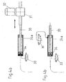
- the oil volume required to change the position of the unbalance piston 17 is metered by displacing an adjusting piston 34 of an actuating cylinder 34a.
- the piston rod 30 of the adjusting piston 34 is connected to a trapezoidal or ball screw drive 31, the spindle of which cannot be displaced (self-locking) when subjected to tensile or compressive stress.
- the screw drive 31 is driven by an electric or hydraulic motor 32.
- An incremental displacement measurement on the piston rod or possibly an angle measurement on the screw drive 31 (preferably integrated therein) and therefore not shown) is used to adjust the eccentricity of the unbalance piston 17 or the nominal amplitude.
- a second oil connection is provided on the piston side, the 2/2-way valve 33 of which can be automatically switched to the flow position depending on the operating state.
- the oil volume required to change the position of the unbalance piston 17 is changed by using a variable oil volume using the adjusting piston 34 and its piston rod 30 on the piston rod side.
- electromagnets of a 3/3-way valve 35 are actuated in cycles so that the adjusting piston 34 can be displaced at very small intervals.
- the adjusting piston 34 moves in the direction of the piston side when the 3/3-way valve 35 is switched under pressure, and in the direction of the piston rod side when the tank is switched due to the centrifugal force of the unbalance piston 17.
- the blocking zero position of the 3/3-way valve 35 here replaces the self-locking effect of the screw drive 31 of FIG. 4a.
- the function of the adjusting piston 34 with the piston rod 30 here is exclusively the incremental displacement measurement for setting the eccentricity of the unbalance piston 17 or the nominal amplitude.
- the calibration and the leak oil compensation correspond to those of Fig. 4a.
- the unbalance piston 17 is in the position shown in FIG. 5b only with the nominal amplitude set to maximum manually or automatically and the minimum operating frequency.
- the 2/2-way valve 33 is switched to flow and the oil pressure corresponds to the inlet pressure of the directional valve. In this operating state, leak oil can be replaced and the system calibrated. As soon as the adjusting piston 34 has reached the position of FIG. 5b, the 2/2-way valve 33 is automatically blocked immediately. The nominal amplitude can then be continuously reduced from this operating state.
- the working frequency is controlled in the direction of the smaller nominal amplitude, for example by means of a map control, in order to avoid exceeding the permissible centrifugal force of the unbalance piston 17.
- the 2/2-way valve 33 is blocked and leakage oil replacement or calibration are not possible.
- the nominal amplitude can be continuously increased from this operating state or reduced.
- the working frequency is controlled in the direction of the smaller nominal amplitude and the position of the unbalance piston 17 is controlled in the direction of the larger nominal amplitude.
- the vibration frequency is adjusted to the nominal amplitude as described above.
- the optimal rolling speed can be set automatically depending on the vibration frequency or displayed to the roller driver.
- the position of the unbalance piston 17 can either be adjusted manually or regulated automatically depending on the density (rigidity) of the substrate.
- tandem vibratory rollers either only the front, only the rear or both roller bodies 2, 3 can be equipped with an unbalance adjustable in the above manner.
- a directional control valve 35 is provided instead of the hydraulic motor 32 of FIGS. 5a to 5c, which is connected to the piston rod-side space of the actuating cylinder 34, while in this case the three-way directional control valve 33 is in turn connected to the space of the actuating cylinder 34a is connected in front of the adjusting piston 34.
- the unbalance cylinder 16 is filled with oil from the hydraulic source via a pump 37 in this embodiment.
- the directional control valve 33 is switched simultaneously with the switching off of the vibration, as shown in FIG. 6a.
- a pressure relief valve 36 is connected to the line from the pump 37 to the directional control valve 33. If the latter responds, this means that the unbalance cylinder 16 is completely filled with oil.
- the directional control valve 33 is switched so that from the actuating cylinder 34a, namely from the space in front of the adjusting piston 34, oil can flow back to the hydraulic source via a pressure relief valve 38, while the previously closed directional control valve 35 is opened, so that hydraulic oil can adjust the adjusting piston 34.
- the amount of oil in the adjusting cylinder 34a is completely returned to the hydraulic source, whereby the system is also calibrated.
- the directional control valves 33, 35 are blocked and the vibration can be switched on, cf. Fig. 6c.
- a certain frequency for example 28 Hz
- the amplitude is adjusted from the position of smallest amplitude shown in FIG. 6c by opening the directional valve 35 accordingly.
Landscapes
- Engineering & Computer Science (AREA)
- Architecture (AREA)
- Civil Engineering (AREA)
- Structural Engineering (AREA)
- Road Paving Machines (AREA)
- Rolls And Other Rotary Bodies (AREA)
- Apparatuses For Generation Of Mechanical Vibrations (AREA)
Applications Claiming Priority (2)
| Application Number | Priority Date | Filing Date | Title |
|---|---|---|---|
| DE10210049 | 2002-03-07 | ||
| DE10210049A DE10210049B4 (de) | 2002-03-07 | 2002-03-07 | Verdichtungswalze |
Publications (3)
| Publication Number | Publication Date |
|---|---|
| EP1342849A2 true EP1342849A2 (fr) | 2003-09-10 |
| EP1342849A3 EP1342849A3 (fr) | 2004-12-01 |
| EP1342849B1 EP1342849B1 (fr) | 2008-07-02 |
Family
ID=27740680
Family Applications (1)
| Application Number | Title | Priority Date | Filing Date |
|---|---|---|---|
| EP03003966A Expired - Lifetime EP1342849B1 (fr) | 2002-03-07 | 2003-02-22 | Rouleau de compactage |
Country Status (5)
| Country | Link |
|---|---|
| US (1) | US20030223817A1 (fr) |
| EP (1) | EP1342849B1 (fr) |
| JP (1) | JP4203725B2 (fr) |
| CN (1) | CN100529263C (fr) |
| DE (2) | DE10210049B4 (fr) |
Cited By (1)
| Publication number | Priority date | Publication date | Assignee | Title |
|---|---|---|---|---|
| CN115157717A (zh) * | 2022-06-29 | 2022-10-11 | 中化工程沧州冷却技术有限公司 | 一种冷却塔用玻璃钢管道的生产工艺 |
Families Citing this family (8)
| Publication number | Priority date | Publication date | Assignee | Title |
|---|---|---|---|---|
| DE102006030628B4 (de) * | 2006-07-03 | 2021-03-04 | F. Weyhausen Ag & Co. Kg Maschinenfabrik | Vorrichtung zur Verdichtung eines Baugrundes |
| US20110158745A1 (en) * | 2009-12-31 | 2011-06-30 | Caterpillar Paving Products Inc. | Vibratory system for a compactor |
| CN105268621B (zh) * | 2015-11-11 | 2018-06-05 | 王存伟 | 无级变幅振动器 |
| DE102021200285A1 (de) | 2021-01-14 | 2022-07-14 | Robert Bosch Gesellschaft mit beschränkter Haftung | Verdichtungsfahrzeug, bei welchem ein Fahrantrieb und eine Vibrationseinheit von einer gemeinsamen Versorgungstelle her mit Druckfluid versorgt werden |
| CN113846540B (zh) * | 2021-10-22 | 2024-02-09 | 李亚辉 | 一种道路桥梁工程路面修复装置 |
| DE102022113204A1 (de) * | 2022-05-25 | 2023-11-30 | Hamm Ag | Bodenbearbeitungswalze |
| CN115369720B (zh) * | 2022-07-29 | 2024-08-16 | 许慧保 | 一种无极变频定向液压振动压路机 |
| CN120649349B (zh) * | 2025-08-20 | 2025-10-28 | 华能牙克石发电有限公司 | 一种道路地基修建压实装置 |
Citations (5)
| Publication number | Priority date | Publication date | Assignee | Title |
|---|---|---|---|---|
| EP0053598B1 (fr) | 1980-12-03 | 1984-09-05 | Geodynamik H Thurner AB | Méthode pour compacter une couche de matière et machine de compactage pour l'application de cette méthode |
| DE4129182A1 (de) | 1991-09-03 | 1993-03-04 | Bomag Gmbh | Verdichtungsgeraet |
| EP0954187A1 (fr) | 1998-04-27 | 1999-11-03 | Nokia Mobile Phones Ltd. | Méthode et appareil pour l'indication de traitement de données à connections des télécommunications |
| DE69425111T2 (de) | 1993-11-30 | 2001-03-22 | Sakai Heavy Industries Ltd., Tokio/Tokyo | Vibrationsmechanismus und Vorrichtung zum Erzeugen von Vibrationen in einer Vibrationswalze mit einstellbarer Amplitude |
| DE10031617A1 (de) | 2000-06-29 | 2002-01-17 | Wacker Werke Kg | Vibrationserreger mit Amplitudenverstellung |
Family Cites Families (8)
| Publication number | Priority date | Publication date | Assignee | Title |
|---|---|---|---|---|
| US3059483A (en) * | 1960-05-31 | 1962-10-23 | Continental Oil Co | Vibrator with hydraulically controlled eccentricity |
| US3656419A (en) * | 1969-04-01 | 1972-04-18 | American Hoist & Derrick Co | Vibratory roller |
| US4105356A (en) * | 1977-05-19 | 1978-08-08 | Koehring Corporation | Vibratory roller |
| AU570233B2 (en) * | 1983-02-18 | 1988-03-10 | Bowater Tutt Industries Pty. Ltd. | Vibratory mechanism |
| US4759659A (en) * | 1987-07-01 | 1988-07-26 | Fernand Copie | Variable vibrator system |
| US6460006B1 (en) * | 1998-12-23 | 2002-10-01 | Caterpillar Inc | System for predicting compaction performance |
| IT1307472B1 (it) * | 1999-07-13 | 2001-11-06 | Bitelli Spa | Tamburo vibrante perfezionato per macchine compattatrici di suoli. |
| JP3725769B2 (ja) * | 1999-10-28 | 2005-12-14 | 酒井重工業株式会社 | ハンドガイドローラ |
-
2002
- 2002-03-07 DE DE10210049A patent/DE10210049B4/de not_active Expired - Fee Related
-
2003
- 2003-02-22 EP EP03003966A patent/EP1342849B1/fr not_active Expired - Lifetime
- 2003-02-22 DE DE50310053T patent/DE50310053D1/de not_active Expired - Lifetime
- 2003-03-05 JP JP2003059232A patent/JP4203725B2/ja not_active Expired - Fee Related
- 2003-03-06 US US10/382,440 patent/US20030223817A1/en not_active Abandoned
- 2003-03-07 CN CNB031105254A patent/CN100529263C/zh not_active Expired - Fee Related
Patent Citations (5)
| Publication number | Priority date | Publication date | Assignee | Title |
|---|---|---|---|---|
| EP0053598B1 (fr) | 1980-12-03 | 1984-09-05 | Geodynamik H Thurner AB | Méthode pour compacter une couche de matière et machine de compactage pour l'application de cette méthode |
| DE4129182A1 (de) | 1991-09-03 | 1993-03-04 | Bomag Gmbh | Verdichtungsgeraet |
| DE69425111T2 (de) | 1993-11-30 | 2001-03-22 | Sakai Heavy Industries Ltd., Tokio/Tokyo | Vibrationsmechanismus und Vorrichtung zum Erzeugen von Vibrationen in einer Vibrationswalze mit einstellbarer Amplitude |
| EP0954187A1 (fr) | 1998-04-27 | 1999-11-03 | Nokia Mobile Phones Ltd. | Méthode et appareil pour l'indication de traitement de données à connections des télécommunications |
| DE10031617A1 (de) | 2000-06-29 | 2002-01-17 | Wacker Werke Kg | Vibrationserreger mit Amplitudenverstellung |
Cited By (2)
| Publication number | Priority date | Publication date | Assignee | Title |
|---|---|---|---|---|
| CN115157717A (zh) * | 2022-06-29 | 2022-10-11 | 中化工程沧州冷却技术有限公司 | 一种冷却塔用玻璃钢管道的生产工艺 |
| CN115157717B (zh) * | 2022-06-29 | 2024-02-09 | 中化工程沧州冷却技术有限公司 | 一种冷却塔用玻璃钢管道的生产工艺 |
Also Published As
| Publication number | Publication date |
|---|---|
| DE50310053D1 (de) | 2008-08-14 |
| EP1342849A3 (fr) | 2004-12-01 |
| DE10210049A1 (de) | 2003-10-09 |
| CN1445415A (zh) | 2003-10-01 |
| US20030223817A1 (en) | 2003-12-04 |
| JP2004003296A (ja) | 2004-01-08 |
| CN100529263C (zh) | 2009-08-19 |
| DE10210049B4 (de) | 2004-03-25 |
| JP4203725B2 (ja) | 2009-01-07 |
| EP1342849B1 (fr) | 2008-07-02 |
Similar Documents
| Publication | Publication Date | Title |
|---|---|---|
| EP1967292B1 (fr) | Générateur de vibrations | |
| DE3239266C2 (fr) | ||
| EP1967291A1 (fr) | Accélérateur d'oscillations | |
| EP2558649B1 (fr) | Agencement pour fournir une force de pression pulsée | |
| EP2740846A1 (fr) | Machine de compactage | |
| DE19932396A1 (de) | Baumaschine sowie Fräswalze | |
| DE19529115A1 (de) | Vibrationsmechanismus, insbesondere zur Verwendung zur Verdichtung von Böden | |
| DE102014018457A1 (de) | Bodenverdichtungsbandage, Walze mit einer solchen Bodenverdichtungsbandage, Schwingungserregungseinrichtung für eine Bodenverdichtungsbandage und Verfahren zur Bodenverdichtung | |
| DE10210049B4 (de) | Verdichtungswalze | |
| EP0023624A2 (fr) | Système de damage ou de frappe à masses compensées | |
| DE3639009A1 (de) | Walze fuer die druckbehandlung von warenbahnen | |
| DE69934696T2 (de) | Verstellbarer exzenterschwinghammer | |
| EP0199922A2 (fr) | Mouton vibrant avec réglage de balourd | |
| DE9312846U1 (de) | Vibrationsbär zum Rammen und/oder Ziehen von Rammgütern | |
| DE102004042369A1 (de) | Bodenbearbeitungsgerät und Verfahren zum Einbringen eines Arbeitselementes in den Boden | |
| EP3450631A1 (fr) | Vibreur en profondeur avec une masse non équilibrée réglable | |
| EP2242590B1 (fr) | Excitateur à balourds comprenant un ou plusieurs balourds rotatifs | |
| DE102011103401A1 (de) | Verfahren zum Steuern oder Regeln einer synchronisierten Vibrationsramme und Vibrationsramme zum Durchführen des Verfahrens | |
| DE3441966A1 (de) | Steuerung fuer einen hydrostatischen kolbenmotor | |
| WO2008009314A1 (fr) | Procédé et machine de stabilisation d'une voie | |
| DE4139798C2 (de) | Vibrationsbär | |
| DE2112533A1 (de) | Schleifwagen fuer Schienen | |
| EP3767033B1 (fr) | Engin de construction automoteur et procédé de traitement des revêtements de sol | |
| DE102018113352B4 (de) | Anbauverdichter | |
| EP2266713B1 (fr) | Générateur d'oscillations |
Legal Events
| Date | Code | Title | Description |
|---|---|---|---|
| PUAI | Public reference made under article 153(3) epc to a published international application that has entered the european phase |
Free format text: ORIGINAL CODE: 0009012 |
|
| AK | Designated contracting states |
Kind code of ref document: A2 Designated state(s): AT BE BG CH CY CZ DE DK EE ES FI FR GB GR HU IE IT LI LU MC NL PT SE SI SK TR |
|
| AX | Request for extension of the european patent |
Extension state: AL LT LV MK RO |
|
| PUAL | Search report despatched |
Free format text: ORIGINAL CODE: 0009013 |
|
| AK | Designated contracting states |
Kind code of ref document: A3 Designated state(s): AT BE BG CH CY CZ DE DK EE ES FI FR GB GR HU IE IT LI LU MC NL PT SE SI SK TR |
|
| AX | Request for extension of the european patent |
Extension state: AL LT LV MK RO |
|
| 17P | Request for examination filed |
Effective date: 20050507 |
|
| AKX | Designation fees paid |
Designated state(s): CH CZ DE GB IT LI SE |
|
| GRAP | Despatch of communication of intention to grant a patent |
Free format text: ORIGINAL CODE: EPIDOSNIGR1 |
|
| GRAS | Grant fee paid |
Free format text: ORIGINAL CODE: EPIDOSNIGR3 |
|
| GRAA | (expected) grant |
Free format text: ORIGINAL CODE: 0009210 |
|
| AK | Designated contracting states |
Kind code of ref document: B1 Designated state(s): CH CZ DE GB IT LI SE |
|
| REG | Reference to a national code |
Ref country code: GB Ref legal event code: FG4D Free format text: NOT ENGLISH |
|
| REG | Reference to a national code |
Ref country code: CH Ref legal event code: EP |
|
| REF | Corresponds to: |
Ref document number: 50310053 Country of ref document: DE Date of ref document: 20080814 Kind code of ref document: P |
|
| REG | Reference to a national code |
Ref country code: CH Ref legal event code: NV Representative=s name: DR. LUSUARDI AG |
|
| REG | Reference to a national code |
Ref country code: SE Ref legal event code: TRGR |
|
| PLBE | No opposition filed within time limit |
Free format text: ORIGINAL CODE: 0009261 |
|
| STAA | Information on the status of an ep patent application or granted ep patent |
Free format text: STATUS: NO OPPOSITION FILED WITHIN TIME LIMIT |
|
| 26N | No opposition filed |
Effective date: 20090403 |
|
| PGFP | Annual fee paid to national office [announced via postgrant information from national office to epo] |
Ref country code: CZ Payment date: 20160219 Year of fee payment: 14 Ref country code: CH Payment date: 20160208 Year of fee payment: 14 Ref country code: IT Payment date: 20160209 Year of fee payment: 14 |
|
| PGFP | Annual fee paid to national office [announced via postgrant information from national office to epo] |
Ref country code: GB Payment date: 20160209 Year of fee payment: 14 Ref country code: SE Payment date: 20160211 Year of fee payment: 14 |
|
| REG | Reference to a national code |
Ref country code: CH Ref legal event code: PL |
|
| REG | Reference to a national code |
Ref country code: SE Ref legal event code: EUG |
|
| GBPC | Gb: european patent ceased through non-payment of renewal fee |
Effective date: 20170222 |
|
| PG25 | Lapsed in a contracting state [announced via postgrant information from national office to epo] |
Ref country code: CZ Free format text: LAPSE BECAUSE OF NON-PAYMENT OF DUE FEES Effective date: 20170222 Ref country code: LI Free format text: LAPSE BECAUSE OF NON-PAYMENT OF DUE FEES Effective date: 20170228 Ref country code: CH Free format text: LAPSE BECAUSE OF NON-PAYMENT OF DUE FEES Effective date: 20170228 |
|
| PG25 | Lapsed in a contracting state [announced via postgrant information from national office to epo] |
Ref country code: SE Free format text: LAPSE BECAUSE OF NON-PAYMENT OF DUE FEES Effective date: 20170223 |
|
| PG25 | Lapsed in a contracting state [announced via postgrant information from national office to epo] |
Ref country code: IT Free format text: LAPSE BECAUSE OF NON-PAYMENT OF DUE FEES Effective date: 20170222 Ref country code: GB Free format text: LAPSE BECAUSE OF NON-PAYMENT OF DUE FEES Effective date: 20170222 |
|
| PGFP | Annual fee paid to national office [announced via postgrant information from national office to epo] |
Ref country code: DE Payment date: 20220225 Year of fee payment: 20 |
|
| REG | Reference to a national code |
Ref country code: DE Ref legal event code: R071 Ref document number: 50310053 Country of ref document: DE |