EP1342853A1 - Dispositif d'affichage d'informations pour machine de chantier - Google Patents
Dispositif d'affichage d'informations pour machine de chantier Download PDFInfo
- Publication number
- EP1342853A1 EP1342853A1 EP01998692A EP01998692A EP1342853A1 EP 1342853 A1 EP1342853 A1 EP 1342853A1 EP 01998692 A EP01998692 A EP 01998692A EP 01998692 A EP01998692 A EP 01998692A EP 1342853 A1 EP1342853 A1 EP 1342853A1
- Authority
- EP
- European Patent Office
- Prior art keywords
- information
- sub
- screen
- displayed
- category
- Prior art date
- Legal status (The legal status is an assumption and is not a legal conclusion. Google has not performed a legal analysis and makes no representation as to the accuracy of the status listed.)
- Granted
Links
Images



















Classifications
-
- B—PERFORMING OPERATIONS; TRANSPORTING
- B66—HOISTING; LIFTING; HAULING
- B66C—CRANES; LOAD-ENGAGING ELEMENTS OR DEVICES FOR CRANES, CAPSTANS, WINCHES, OR TACKLES
- B66C13/00—Other constructional features or details
- B66C13/18—Control systems or devices
-
- E—FIXED CONSTRUCTIONS
- E02—HYDRAULIC ENGINEERING; FOUNDATIONS; SOIL SHIFTING
- E02F—DREDGING; SOIL-SHIFTING
- E02F9/00—Component parts of dredgers or soil-shifting machines, not restricted to one of the kinds covered by groups E02F3/00 - E02F7/00
- E02F9/20—Drives; Control devices
- E02F9/22—Hydraulic or pneumatic drives
- E02F9/2278—Hydraulic circuits
- E02F9/2296—Systems with a variable displacement pump
-
- E—FIXED CONSTRUCTIONS
- E02—HYDRAULIC ENGINEERING; FOUNDATIONS; SOIL SHIFTING
- E02F—DREDGING; SOIL-SHIFTING
- E02F9/00—Component parts of dredgers or soil-shifting machines, not restricted to one of the kinds covered by groups E02F3/00 - E02F7/00
- E02F9/26—Indicating devices
-
- G—PHYSICS
- G06—COMPUTING OR CALCULATING; COUNTING
- G06F—ELECTRIC DIGITAL DATA PROCESSING
- G06F3/00—Input arrangements for transferring data to be processed into a form capable of being handled by the computer; Output arrangements for transferring data from processing unit to output unit, e.g. interface arrangements
- G06F3/01—Input arrangements or combined input and output arrangements for interaction between user and computer
- G06F3/048—Interaction techniques based on graphical user interfaces [GUI]
Definitions
- the present invention relates to an information display unit for a construction machine and a display control unit. More particularly, the present invention relates to an information display unit for a construction machine, which is provided in a cab of the construction machine and is capable of displaying plural kinds of information such as body information and maintenance information, as well as to a display control unit for the information display unit.
- JP-A 5-288648 discloses a managing and monitoring unit which has a plurality of display modes for displaying body working information, maintenance information, etc., and which is capable of changing the contents to be displayed upon switch manipulation.
- JP-A 5-287782 discloses a multi-function display monitoring system in which a display panel comprises a display portion and a switch portion.
- the monitoring system monitors excavation situations of an excavator, such as a power shovel, and displays a symbolic illustration in imitation of the excavator along with numerical information. The contents of displayed information regarding the front attitude can be changed upon switch manipulation.
- JP-A 10-103925 discloses an excavation control method employing an excavation information monitoring unit for an excavator, in which the contents to be displayed are changed with a touch panel.
- a plurality of display modes are selectively changed depending on a vehicle status or in response to an operation instruction, and an image having the contents corresponding to the selected display mode is displayed on one screen.
- the contents displayed on the screen are completely altered with a display mode change, the operator cannot see plural kinds of information at the same time, for example, by additionally displaying maintenance information while working information is being displayed.
- the monitoring units disclosed in JP-A 10-103925 and JP-A 5-287782 similarly display information of one function only, such as body information of an excavator, on one screen, and alter the displayed contents by changing an entire image on the screen.
- Fig. 1 is a block diagram showing an electronic control system of a hydraulic excavator equipped with an information display unit according to a first embodiment of the present invention, along with the hydraulic excavator and a hydraulic system mounted therein.
- a hydraulic excavator 1 comprises a track body 2, a swing body 3, an excavation working device (front working mechanism) 7.
- the excavation working device 7 is made up of a boom 8 vertically pivotably mounted to the swing body 3, an arm 9 rotatably mounted to a fore end of the boom 8, a bucket 10 rotatably mounted to a fore end of the arm 9, a boom operating hydraulic cylinder 11 for vertically pivoting the boom 8, an arm operating cylinder 12 for rotating the arm 9, and a bucket operating hydraulic cylinder 13 for rotating the bucket 10.
- the swing body 3 has an accommodating room 4 for accommodating an engine 14 and hydraulic equipment such as a hydraulic pump 18.
- a cab 6 is provided on the front left side of the swing body 3.
- the engine 14 is provided with an electronic governor 15 for maintaining the revolution speed of the engine 14 within a certain range.
- a target revolution speed Nr of the engine 14 set by a target revolution speed setting unit 16.
- the hydraulic pump 18 is driven for rotation by the engine 14. Also, the hydraulic pump 18 is a variable displacement pump and is provided with a swash plate 19 for varying a pump delivery rate. A delivery rate adjusting device 20 is coupled to the swash plate 19. Further, there are provided a swash plate position sensor 21 for detecting a tilting position ⁇ of the swash plate 19, and a pressure sensor 22 for detecting a delivery pressure Pd of the hydraulic pump 18.
- the boom operating hydraulic cylinder 11, the arm operating cylinder 12, and the bucket operating hydraulic cylinder 13 are connected to the hydraulic pump 18 through control valves 24, 25, 26, respectively. Flow rates and directions of hydraulic fluids supplied from the hydraulic pump 18 to the respective cylinders 11, 12, 13 are adjusted by the control valves 24, 25, 26.
- Control levers 27, 28, 29 are provided in association with the control valves 24, 25, 26, and lever operating units 30, 31, 32 are coupled to the control levers 27, 28, 29, respectively.
- the lever operating units 30, 31, 32 output, as operating signals X1, X2, X3 for the control levers 27, 28, 29, electrical signals depending on shift amounts by which the respective control levers are operated.
- the excavation working device 7 is provided with a boom rotational angle sensor 35 for detecting a rotational angle ⁇ of the boom 8, an arm rotational angle sensor 36 for detecting a rotational angle ⁇ of the arm 9, and a bucket rotational angle sensor 38 for detecting a rotational angle ⁇ of the bucket 10.
- a first control unit 17, a second control unit 23, a third control unit 33 and a fourth control unit 37 are provided for controlling various components of the hydraulic excavator, and a first monitoring unit 45, a second monitoring unit 46 and an information display unit 47 are provided for giving an operator information regarding the inside and outside of a machine body.
- the first to fourth control units 17, 23, 33, 37, the first and second monitoring unit units 45, 46, and the information display unit 47 are interconnected via a communication line 46 for transmitting and receiving data among them.
- the first control unit 17 controls the engine 14. More specifically, the first control unit 17 receives the target revolution speed Nr from the target revolution speed setting unit 16 and an actual revolution speed Ne detected by the governor 15, and then executes predetermined computations, thereby outputting a control signal R to the governor 15. As a result, the engine 14 is controlled such that the actual revolution speed Ne matches with the target revolution speed Nr from the target revolution speed setting unit 16.
- the second control unit 23 controls the hydraulic pump 18. More specifically, the second control unit 23 receives the delivery pressure Pd of the hydraulic pump 18 detected by the pressure sensor 22, the tilting position ⁇ of the swash plate 19 detected by the swash plate position sensor 21, and the operating signals X1 to X7 from the third control unit 33, and then executes predetermined computations, thereby outputting a control signal for the swash plate 19 to the delivery rate adjusting device 20 for the hydraulic pump 18. As a result, the delivery rate of the hydraulic pump 18 is adjusted with the operation of the delivery rate adjusting device 20.
- the third control unit 33 controls the control valves 24, 25, 26. More specifically, the third control unit 33 receives electrical signals from the lever operating units 30, 31, 32 and then executes predetermined computations, thereby outputting control signals to operating sectors 24L, 24R, 25L, 25R, 26L, 26R of the control valves 24, 25, 26. As a result, respective shift positions of the control valves 24, 25, 26 are controlled in accordance with the operating signals X1, X2, X3 from the control levers 27, 28, 29, whereby the flow rates and flowing directions of the hydraulic fluids supplied to the cylinders 11, 12, 13 are controlled.
- the third control unit 33 receives, from those control lever units, a swing operating signal X4, left and right track operating signals X5, X6, and an operating signal X7 for an attachment separate from the bucket 10 that is equipped as a standard option, and then executes predetermined computations, thereby outputting control signals to control valves (not shown). As a result, the flow rates and flowing directions of the hydraulic fluids supplied to respective actuators (not shown) are controlled.
- the fourth control unit 37 controls the excavation working device 7. More specifically, the fourth control unit 37 receives respective signals for the rotational angles ⁇ , ⁇ , ⁇ from the rotational angle sensors 35, 36, 38 and the operating signals X1, X2, X3 of the control lever units 27, 28, 29 from the third control unit 33, and then executes predetermined computations, thereby modifying the operating signals X1, X2, X3 and outputting control driving commands Y ⁇ , Y ⁇ , Y ⁇ to the third control unit 33. As a result, the control valves 24, 25, 26 are controlled so as to control, for example, the locus of the excavation working device 7 in its operation.
- the engine 14 is provided with a hydraulic pressure sensor 41 for measuring a pressure Poil of a lubricant (engine oil), and a radiator 51 for cooling engine cooling water is provided with a water temperature sensor 42 for detecting a cooling water temperature Tw. Respective signals of the engine oil pressure Poil and the cooling water temperature Tw detected by the sensors 41, 42 are inputted to the first control unit 17.
- a fuel level sensor 43 for measuring a fuel level (amount of fuel remaining) Fuel
- a pressure sensor 44 for detecting a filter pressure Pfit of a filter 50 provided in a hydraulic system circuit to detect clogging of the filter 50
- a hydraulic fluid temperature sensor 56 for detecting a temperature T 0 of the hydraulic fluid in the hydraulic system
- a tilt sensor 49 for detecting a body tilt angle ⁇ .
- Respective signals of the fuel level Fuel, the filter pressure Pfit, and the hydraulic fluid temperature T 0 detected by the sensors 43, 44 are inputted to the first monitoring unit 45.
- a signal of the hydraulic fluid temperature T 0 detected by the sensor 56 is inputted to the second control unit 23, and a signal of the body tilt angle ⁇ detected by the tilt sensor 49 is inputted to the fourth control unit 37.
- the first monitoring unit 45 transmits information of the fuel level Fuel and the filter pressure Pfit, which are detected respectively by the sensors 43, 44, to the information display unit 47.
- the information display unit 47 When an instrument panel is provided in the cab 6, those items of information are displayed on the instrument panel.
- the second monitoring unit 46 receives detection data (described later) from the first control unit 17, the second control unit 23 and the first monitoring unit 45 via the communication line 40, and then processes those data for time-serially or statistically measuring and the storing abnormality detection history, the machine working time, the working status, etc. Further, the second monitoring unit 46 transmits those items of information to the information display unit 47.
- the information display unit 47 receives various kinds of information (described later) from the first to fourth control units 17, 23, 33, 37 and the first and second monitoring units 45, 46 via the communication line 40, and then displays the received information. Also, the information display unit 47 has the function of instructing, e.g., a target locus in works of the excavation working device 7 to the fourth control unit 37.
- Fig. 2 shows a configuration of the information display unit 47.
- the information display unit 47 comprises an operating portion 470 serving as input means, a display control portion 471, and a display portion 472 having a screen 472a, such as an LCD.
- the operating portion 470 includes various switches such as upward and downward arrow keys 470a, 470b and leftward and rightward arrow keys 470c, 470d which are depressed, for example, when the operator wants to change a display image, numerical value increment and decrement entry keys 470e, 470f which are depressed, for example, when the operator enters a target value for control, and a mode switch (not shown).
- switches such as upward and downward arrow keys 470a, 470b and leftward and rightward arrow keys 470c, 470d which are depressed, for example, when the operator wants to change a display image, numerical value increment and decrement entry keys 470e, 470f which are depressed, for example, when the operator enters a target value for control, and a mode switch (not shown).
- the display control portion 471 comprises an interface 471a for receiving signals from the operating portion 470, a central processing unit (CPU) 471b, a read only memory (ROM) 471c for storing programs for control procedures and constants necessary for control, a random access memory (RAM) 471d for temporarily storing numerical values given as computed results or obtained in the course of computation, an output interface (I/F) 471e, and a communication controller 471f for controlling communication with the first to fourth control units 17, 23, 33, 37 and the first and second monitoring unit units 45, 46 which are all connected to the common communication line 40.
- CPU central processing unit
- ROM read only memory
- RAM random access memory
- I/F output interface
- communication controller 471f for controlling communication with the first to fourth control units 17, 23, 33, 37 and the first and second monitoring unit units 45, 46 which are all connected to the common communication line 40.
- the information display unit 47 is disposed inside the cab 6.
- the operating portion 470, the display control portion 471, and the display portion 472 of the information display unit 47 are preferably constructed as separate units, and the display portion 472 is attached to such a position inside the cab 6 as allowing the operator to see it with ease, e.g., at a corner of the cab on the obliquely right-hand side looking from an operator' s seat.
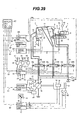
- Fig. 3 shows, in the form of a table, details of communication data transmitted and received among the control units and the monitoring units via the common communication line 40.
- ID No. represents an ID number assigned to individual data.
- a mark 0 represents data transmitted from the control unit or the monitoring unit.
- a mark ⁇ represents data received by the control unit or the monitoring unit.
- Communication Cycle represents an interval at which the control unit transmitting data transmits that data, i.e., a time interval at which data is updated.
- “upon display manipulation” indicates that a signal is transmitted to the information display unit 27 only when an instruction button (not shown) provided in the operating portion 470 of the information display unit 47 is manipulated.
- the second monitoring unit 46 receives data of the actual engine revolution speed Ne, the engine oil pressure Poil and the cooling water temperature Tw from the first control unit 17, data of the pump delivery pressure Pd, the pump tilting angle ⁇ and the hydraulic fluid temperature T 0 from the second control unit 23, the arm operating signal X2, the swing operating signal X4, the left and right track operating signal X5, X6 and the attachment operating signal X7 from the third control unit 33, and data of the fuel level Fuel and the filter pressure Pfit from the first monitoring unit 45.
- the second monitoring unit 46 prepares various data, i.e., abnormality detection history HisW, working time (key-on) TmwKey, working time (engine-on) TmwEng, working time (excavation) TmwExc, working time (travel) TmwRun, working time (swing) TmwRot, working time (ML) TmwML, working time (ATT) TmwATT, engine revolution speed frequency distribution HistEng, cooling water temperature frequency distribution HistTw, hydraulic fluid temperature frequency distribution HistT 0 , pump load frequency distribution HistPld, and excavation load frequency distribution HistEld.
- Those data are transmitted to the information display unit 47 along with information of time-of-day Time based on RTC (clock function) built in the second monitoring unit 46.
- the data of the abnormality detection history HisW is prepared from data of the engine oil pressure Poil, the cooling water temperature Tw, the pump delivery pressure Pd, etc.
- the working time (key-on) TmwKey is calculated as a power-on time in the second monitoring unit 46.
- the working time (engine-on) TmwEng is calculated as an on-time of the engine revolution speed Ne.
- the working time (excavation) TmwExc is calculated as an on-time of the arm operating signal X2.
- the working time (travel) TmwRun is calculated as an on-time of the left and right track operating signals X5, X6.
- the working time (swing) TmwRot is calculated as an on-time of the swing operating signal X4.
- the working time (ML) TmwML is calculated as an on-time of a signal from an ML mode switch (not shown).
- the working time (ATT) TmwATT is calculated as an on-time of the attachment operating signal X7.
- the engine revolution speed frequency distribution HistEng is prepared by processing data of the engine revolution speed Ne so as to obtain a frequency distribution thereof.
- the cooling water temperature frequency distribution HistTw is prepared by processing data of the cooling water temperature Tw so as to obtain a frequency distribution thereof.
- the hydraulic fluid temperature frequency distribution HistT 0 is prepared by processing data of the hydraulic fluid temperature T 0 so as to obtain a frequency distribution thereof.
- the pump load frequency distribution HistPld is prepared by processing data of the pump delivery pressure Pd so as to obtain a frequency distribution thereof.
- the excavation load frequency distribution HistEld is prepared by processing data of the pump delivery pressure Pd, which is obtained when the arm operating signal X2 is turned on, so as to obtain frequency distribution thereof.
- the information display unit 47 receives the data of data of the actual engine revolution speed Ne, the engine oil pressure Poil and the cooling water temperature Tw from the first control unit 17, the data of the hydraulic fluid temperature T 0 from the second control unit 23, the data of the control driving commands Y ⁇ , Y ⁇ , Y ⁇ , the rotational angles ⁇ , ⁇ , ⁇ of the boom, the arm and the bucket, a depth (height) hx of the bucket fore end and a reach hy of the bucket fore end from the fourth control unit 37, the data of the fuel level Fuel and the filter pressure Pfit from the first monitoring unit 45, and the above-mentioned various data from the second monitoring unit 46. Then, the information display unit 47 displays the received data while changing and combining them properly.
- a screen image displayed on the screen 472a of the display portion 472 (hereinafter referred to as a displayed screen image) displays information regarding plural kinds of information categories at the same time. On that occasion, information of one category among the plural kinds of information categories is displayed in detail, and information of the other categories is displayed in the simplified form. Which one of the information categories is to be displayed in detail can be changed in turn upon key manipulation made on the operating portion 470 (Fig. 2) by the operator.
- the displayed screen image has a main display area 1000 and a sub-display area 2000 that are located in preset positions.
- the main display area 1000 represents an area for detailed display
- the sub-display area 2000 represents an area for simplified display.
- the main display area 1000 displays one main screen 1002
- the sub-display area 2000 displays sub-screens 2005, 2006, 2003, 2004 in the same number as the number of the information categories.
- the sub-screens correspond to the information categories in a one-to-one relation.
- the main display area 1000 displays one main screen 1001, and the sub-display area 2000 displays sub-screens 2001 to 2004 in the same number as the number of the information categories.
- the main display area 1000 displays one main screen 1003, and the sub-display area 2000 displays sub-screens 2001, 2006, 2007, 2004 in the same number as the number of the information categories.
- the main display area 1000 displays one main screen 1004, and the sub-display area 2000 displays sub-screens 2001, 2006, 2003, 2008 in the same number as the number of the information categories.
- the sub-screens correspond to the information categories in a one-to-one relation.
- Each of the main screens 1001 to 1004 displays the information regarding the corresponding information category in detail.
- the symbolic illustrations 80, 81 for operation guide serve as aids for the operator to change the information category with key manipulation made on the operating portion 470, and are designed in imitation of the upward and downward arrow keys 470a, 470b (Fig. 2) on the operating portion 470.
- the other sub-screens 2006, 2003, 2004 (Fig. 4), 2001, 2003, 2004 (Fig. 5), 2001, 2006, 2004 (Fig. 6), and 2001, 2006, 2003 (Fig. 7) display information that belongs to the corresponding information categories in the simplified form.
- the simplified display is performed, for example, by displaying information regarding a typical one of the corresponding information categories.
- the sub-screens 2005, 2006, 2003, 2004 (Fig. 4), 2001 to 2004 (Fig. 5), 2001, 2006, 2007, 2004 (Fig. 6), and 2001, 2006, 2003, 2008 (Fig. 7) are each arranged so as to serve also as an index (guide) tag for the corresponding information category, and are designed with layout so as to provide index tags for the main display area 1000.
- the information category to be displayed in the main display area 1000 in detail can be changed by newly selecting the sub-screen 2001 corresponding to the desired information category instead of the sub-screen 2002 corresponding to the currently selected information category. That selection can be made by manipulating the upward arrow keys 470a (Fig. 2) with the aid of the symbolic illustration 80 for operation guide (as described later). Upon that manipulation, the information, which has been so far displayed in the sub-screen 2001 corresponding to the newly selected information category in the simplified form, is shifted to the main screen 1002 and is displayed in detail. In the sub-screen 2005, the name of the selected information category and the symbolic illustration 80 for operation guide are displayed instead. Also, the detailed information on the main screen 1001 corresponding to the information category, which has been so far selected, is shifted to be display on the sub-screen 2006 in the simplified form after change of the screen image.
- meter information i.e., meter information, body attitude information, working information, and abnormality warning information
- a description is made of the contents of the displayed screen image in the state in which those information categories are selected one by one.
- the main screen 1002 of the displayed screen image is a screen corresponding to an instrument panel, and displays an engine revolution speed 1200, a cooling water temperature 1201, a hydraulic fluid temperature 1202, and a fuel level 1203 using numerical values, a circle type meter and a bar type meter.
- the sub-screen 2005 displays the name of the selected information category and the symbolic illustration 80 for operation guide to the operator.
- the sub-screens 2006, 2003, 2004 correspond to the body attitude information, the working information and the abnormality warning information, respectively, and display the information (typical items) regarding the respective information categories in the simplified form.
- the sub-screen 2006 displays the attitude and fore end position of the bucket using numerical values and a symbolic illustration.
- the sub-screen 2003 displays the engine-on time and the accumulated excavation time using numerical values.
- the sub-screen 2004 displays an abnormality item in the event of an abnormality. «Category B» In Fig.
- the main screen 1001 of the displayed screen image is a screen displaying the bucket attitude and the body attitude, and displays a body transverse tilt angle 1100, a bucket rotational angle 1101 and a bucket height 1102 using numerical values and a symbolic illustration in imitation of an entire image or each component of the actual machine.
- the sub-screen 2002 displays the name of the selected information category and the symbolic illustrations 80, 81 for operation guide to the operator.
- the sub-screens 2001, 2003, 2004 correspond to the meter information, the working information and the abnormality warning information, respectively, and display the information (typical items) regarding the respective information categories in the simplified form.
- the sub-screen 2001 displays the cooling water temperature, the hydraulic fluid temperature and the fuel level using needle type meters.
- the sub-screens 2003, 2004 display the same contents as those described above.
- the main screen 1003 of the displayed screen image is a screen displaying information of the working time, and displays a key-on time 1300, an engine-on time 1301, an excavation time 1302, a travel time 1303, a swing time 1304, an ML crane operating time 1305 and an attachment operating time 1306 using numerical values and bar type meters.
- the sub-screen 2007 displays the name of the selected information category and the symbolic illustrations 80, 81 for operation guide to the operator.
- the sub-screens 2001, 2006, 2004 correspond to the meter information, the body attitude information and the abnormality warning information, respectively, and display the information (typical items) regarding the respective information categories in the simplified form.
- the main screen 1004 of the displayed screen image is a screen displaying abnormality warning, and displays abnormality occurrence history and failure occurrence history along with the date/time of occurrence of each abnormality or failure.
- the sub-screen 2008 displays the name of the selected information category and the symbolic illustration 81 for operation guide to the operator.
- the sub-screens 2001, 2006, 2003 correspond to the meter information, the body attitude information and the working information, respectively, and display the information (typical items) regarding the respective information categories in the simplified form.
- This block 10010 executes processing to change the display status flag depending on the arrow key depressed.
- the processing flow is shown in Fig. 9.
- This block 10020 executes processing to display the main screen in accordance with the display status flag.
- the processing flow is shown in Fig. 10.
- This block 10030 executes processing to display the sub-screen corresponding to the information category selected by the display status flag.
- the processing flow is shown in Fig. 11.
- This block 10040 executes processing to display the sub-screen corresponding to the information category not selected by the display status flag.
- the processing flow is shown in Fig. 12.
- the main screen image can be changed from the screen of the meter information category A in the initial state to the screen of the working information category C.
- a screen image displayed on the display portion 472 of the information display unit 47 includes the main display area 1000 having one main screen and the sub-display area 2000 having a plurality of sub-screens so that a plurality of information categories can be displayed in both the detailed and simplified forms and the displayed information can be changed in turn. It is therefore possible to display plural kinds of information in a combined and selective manner, and to improve efficiency at which the operator confirms the information.
- the sub-screen in the sub-display area 2000 corresponding to the information category, for which information is displayed in detail on the main screen in the main display area 1000 displays the symbolic illustrations 80, 81 for operation guide, which are provided in imitation of arrow keys and serve as aids for the operator when changing the information category with key manipulation made on the operating portion 470. Therefore, the operator can easily change the information category displayed in the main display area 1000 with key manipulation made on the operating portion 470.
- the plurality of sub-screens in the sub-display area 2000 serve also as index tags for the information category displayed on the main screen in the main display area 1000, and are designed with layout in imitation of index tags for the main display area 1000.
- index tags By using the index tags as guides, therefore, the operator can easily select the information category displayed in the main display area 1000.
- the operator is not required to carefully look at an instrument panel separately mounted inside the cab for confirming the meter information, thus resulting in an improvement of operability and safety.
- the instrument panel mounted inside the cab can be itself dispensed with, it is possible to realize effective utilization of a space within the cab. Additionally, because the abnormality warning information is displayed, maintenance is facilitated.
- the second embodiment differs in device configuration from the first embodiment in that the contents displayed on the information display unit 47 corresponding to some of the information categories are divided into sub-categories, and a means for selectively changing the sub-categories from one to another in the relevant information category is provided in addition to the means for selectively changing the information category from one to another, thus enabling the displayed contents to be changed in a finer divided manner.
- Display information set as the displayed screen image for each information category will be first described with reference to Fig. 14.
- the category A is the same as that in the first embodiment.
- the main screen 1001 of the displayed screen image selectively displays one of the screen displaying the bucket attitude and the body attitude, which has been described above in connection with the first embodiment, and a screen displaying the working device attitude, which is newly added in this embodiment.
- the screen displaying the bucket attitude and the body attitude is the same as that shown in Fig. 5.
- Fig. 5 the screen displaying the bucket attitude and the body attitude
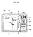
- the screen displaying the working device attitude displays change in the attitude attributable to changes in respective articulation angles of the boom, the arm and the bucket by using a side view 1103 including an overall image of the actual machine.
- the bucket end position is displayed with a numerical value.
- the sub-screen 2002 corresponding to the selected information category and the other sub-screens 2001, 2003, 2004 are the same as those in the first embodiment except that a symbolic illustration 82 for operation guide is additionally displayed in the sub-screen 2002.
- the symbolic illustration 82 for operation guide serves as an aid for shift from the main category (hierarchy 1) to the sub-category with key manipulation made on the operating portion 470, and is designed in imitation of the leftward arrow key 470c on the operating portion 470.
- the main display area 1000 additionally displays symbolic illustrations 83, 84 for operation guide, which are in imitation of the upward and downward arrow keys 470a, 47b on the operating portion 470, as aids for changing the sub-category with key manipulation made on the operating portion 470, and a symbolic illustration 85 for operation guide, which is in imitation of the rightward arrow key 470d on the operating portion 470, as an aid for shift from the sub-category to the main category.
- the main screen 1003 of the displayed screen image selectively displays, as shown in Fig.
- a sub-category level of the frequency distribution is divided into five sub-categories (hierarchy 3), i.e., the engine revolution speed frequency distribution, the cooling water temperature frequency distribution, the hydraulic fluid temperature frequency distribution, the excavation load frequency distribution, and the pump load frequency distribution. Any of those frequency distributions is selected and displayed.
- the screen displaying information of the working time is the same as that shown in Fig. 6.
- the screen displaying the engine revolution speed frequency distribution displays a distribution 1307 of the working time with respect to the engine revolution speed, as shown in Fig. 18.
- the screen displaying the cooling water temperature frequency distribution displays a distribution 1308 of the working time (engine running time) with respect to the cooling water temperature, as shown in Fig. 19.
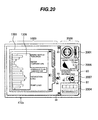
- the screen displaying the hydraulic fluid temperature frequency distribution displays a distribution 1309 of the working time (engine running time) with respect to the hydraulic fluid temperature, as shown in Fig. 20.
- the screen displaying the excavation load frequency distribution displays a distribution 1310 of the excavation operating time with respect to the excavation load, as shown in Fig. 21.
- the screen displaying the pump load frequency distribution displays a distribution 1311 of the pump operating time (engine running time) with respect to the pump load, as shown in Fig. 22.
- the sub-screen 2007 corresponding to the selected information category and the other sub-screens 2001, 2006, 2004 are the same as those in the first embodiment except that the symbolic illustration 82 for operation guide is additionally displayed in the sub-screen 2007.
- the symbolic illustrations 83, 84, 85 for operation guide are displayed in the main display area 1000 as with the information category B.
- a symbolic illustration 86 for operation guide is further displayed in the main display area 1000, as shown in Figs. 18 to 22.
- the symbolic illustration 86 for operation guide serves as an aid for shift from the sub-category (hierarchy 2) to the lower sub-category (hierarchy 3) with key manipulation made on the operating portion 470, and is designed in imitation of the leftward arrow key 470c on the operating portion 470.
- Category D The category D is the same as that in the first embodiment.
- the screens displayed as described above are given with respective label names as shown in Fig. 14.
- the meter information screen of the category A is named A-0-0.
- the body attitude information screen of the category B is named B-1-0, and the working device attitude information screen of the category B is named B-2-0.
- the working information screen of the category C is named C-1-0, the engine revolution speed frequency distribution screen of the category C is named C-2-1, the cooling water temperature frequency distribution screen of the category C is named C-2-2, the hydraulic fluid temperature frequency distribution screen of the category C is named C-2-3, the excavation load frequency distribution screen of the category C is named C-2-4, and the pump load frequency distribution screen of the category C is named C-2-5.
- the abnormality warning information screen of the category D is named D-0-0.
- the first character of the label represents the type of category.
- the second character of the label represents the type of sub-category (hierarchy 2) if it exists.
- the third character of the label represents the type of lower sub-category (hierarchy 3) if it exists.
- the second and third characters are set to 0.
- the category D has no sub-category
- the second and third characters are set to 0.
- the category B has two sub-categories at the hierarchy 2
- those sub-categories are named B-1 and B-2. Since each of B-1 and B-2 has no hierarchy 3, the third character of the label for the category B is set to 0.
- the labels of the screens belonging to the category B are given as B-1-0 and B-2-0.
- C-1 has two sub-categories at the hierarchy 2
- those sub-categories are named C-1 and C-2.
- C-1 has no hierarchy 3
- the label of the screen belonging to the category C-1 is given as C-1-0.
- C-2 has five sub-categories at the hierarchy 3
- the labels of the screens belonging to the category C-2 are given as C-2-1, C-2-2, C-2-3, C-2-4, and C-2-5 in order.
- the screen A-0-0 is displayed.
- B is selected upon category change
- the screen B-1-0 or the screen B-2-0 is displayed.
- C is selected upon category change
- the screen C-1-0, the screen C-2-1, the screen C-2-2, the screen C-2-3, the screen C-2-4, or-the screen C-2-5 is displayed.
- D is selected upon category change
- the screen D-0-0 is displayed.
- Fig. 23 is a block diagram showing screen transition in an initial state.
- the engine revolution speed frequency distribution screen C-2-1 is selected as the frequency distribution from among ones from the engine revolution speed frequency distribution C-2-1 to the pump load frequency distribution C-2-5.
- the frequency distribution C-2-1 is selected as the working information and set as the initial state.
- the bucket attitude and body tilt B-1-0 and the working device attitude B-2-0 the bucket attitude and body tilt B-1-0 is selected as the body attitude information and set as the initial state.
- the screen A-0-0 and the screen D-0-0 are set as the initial state.
- the initial screen is set so as to display the category A. Accordingly, the screen A-0-0 is displayed as the initial screen at the start-up of the information display unit 47.
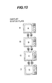
- the screen displaying process will be described below using a display status flag indicating the current display status. It is assumed that any of the label names assigned to the respective displayed screen images is set to the display status flag in accordance with transition of the display status.
- the processing flow is shown in Fig. 24.
- This block 10110 executes processing to change the display status flag depending on the arrow key depressed.
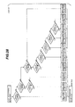
- the rightward direction in Fig. 23 represents a lower level of the sub-category hierarchy, but the leftward arrow key 470c (hereinafter indicated as “ ⁇ " for brevity) is assigned to instruct a transition to the lower hierarchy level and the rightward arrow key 470d (hereinafter indicated as " ⁇ " for brevity) is assigned to instruct a transition to a higher hierarchy level in the following manipulation example in match with the display screen layout.
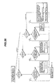
- the processing flows are shown in Figs. 25 to 27.
- This block 10120 executes processing to draw the main screen corresponding to the label name set to the display status flag.
- the detailed drawing process for each main screen has been described above, and hence a repeated description thereof is omitted here.
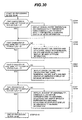
- the processing flow is shown in Fig. 28.
- This block 10130 executes processing to display the sub-screen corresponding to the information category that corresponds to the first character of the label name set to the display status flag, i.e., the information category that is currently selected.
- the processing flow is shown in Fig. 29.
- This block 10140 executes processing to display the sub-screen corresponding to the information category not selected by the first character of the label name set to the display status flag.
- the processing flow is shown in Fig. 30.
- Procedures for changing the main screen image from the meter information screen A-0-0 in the initial state to the working device attitude B-2-0 will be described as a first manipulation example in the second embodiment with reference to screen transition block diagrams of Figs. 31A to 31D.
- the main screen image can be changed from the meter information screen A-0-0 in the initial state to the working device attitude B-2-0.
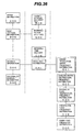
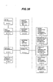
- Procedures for changing the main screen image from the working device attitude B-2-0 to the hydraulic fluid temperature frequency distribution C-2-3 will be described as a second manipulation example in the second embodiment with reference to screen transition block diagrams of Figs. 32 to 38.
- the main screen image can be changed from the working device attitude B-2-0 to the hydraulic fluid temperature frequency distribution C-2-3.
- This second embodiment can provide the following advantages in addition to the above-described advantages obtainable with the first embodiment.
- the categories B, C each include a combination of plural items of sub-category information.
- the main screen in the main display area 1000 selectively displays one of the plural items of sub-category information, and the sub-category information displayed on the main screen can be selected and changed with key manipulation made on the operating portion 470. It is therefore possible to increase the number of kinds of information categories capable of being displayed in the main display area 1000, and to display plural kinds of information in a combined and selective manner.
- the sub-screen in the sub-display area 2000 corresponding to the information category, to which the selected sub-category information belongs displays not only the symbolic illustrations 80, 81 for operation guide, which are in imitation of arrow keys and serve as aids for the operator when changing the information category with key manipulation made on the operating portion 470, but also the symbolic illustrations 82 to 86 for operation guide, which are provided in imitation of arrow keys and serve as aids for the operator when changing the sub-category information with key manipulation made on the operating portion 470. Even with an increase in the number of kinds of information to be displayed, therefore, the operator can easily change the information displayed in the main display area 1000 with key manipulation made on the operating portion 470.
- control units and the monitoring units are connected to the information display unit via one common communication line in the first and second embodiments, the control units and the monitoring units are connected to the information display unit via respective independent communication lines in this embodiment.
- the first to fourth control units 17, 23, 33, 37 and the first and second monitoring units 45, 46 are connected to the information display unit 47 via individual communication lines 90 to 95, respectively.
- the information display unit 47 transmits and receives data to and from the control units and the monitoring units via the communication lines 90 to 95.
- the information display unit 47 comprises an operating portion 470, a display control portion 471, and a display portion 472 (Fig. 2) that are similar to those in the first and second embodiments.
- This third embodiment can also provide the similar advantages to those obtainable with the first and second embodiments.
- a fourth embodiment of the present invention will be described with reference to Figs. 40 to 56. While the screen image displayed on the screen of the display portion of the information display unit (i.e., the displayed screen image) is divided into the main display area and sub-display area in the first and second embodiments, the displayed screen image is not so clearly divided into areas in this fourth embodiment so that the sub-screen has flexibility in position at which it is displayed.
- the screen image displayed on the screen of the display portion of the information display unit i.e., the displayed screen image
- the displayed screen image is not so clearly divided into areas in this fourth embodiment so that the sub-screen has flexibility in position at which it is displayed.
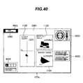
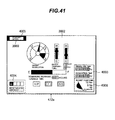
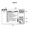
- Figs. 40 to 43 correspond respectively to Figs. 5, 4, 6 and 7 described above in connection with the first embodiment.
- the screen 472a of the display portion 472 displays a screen image comprising one main screen 3001 and sub-screens 4001, 4002, 4003, 4004 in the same number as the information categories.
- the screen 472a displays a screen image comprising one main screen 3002 and sub-screens 4003, 4004, 4005, 4006 in the same number as the information categories.
- the screen 472a displays a screen image comprising one main screen 3003 and sub-screens 4001, 4004, 4006, 4007 in the same number as the information categories.
- Fig. 40 the screen 472a of the display portion 472 (see Fig. 2) displays a screen image comprising one main screen 3001 and sub-screens 4001, 4002, 4003, 4004 in the same number as the information categories.
- the screen 472a displays a screen image comprising one main screen 3002 and sub-screens 4003, 4004, 4005, 4006 in the same number as the information categories
- the screen 472a displays a screen image comprising one main screen 3004 and sub-screens 4001, 4003, 4006, 4008 in the same number as the information categories.
- the main screens 3001 to 3004 are each not defined by definite boundary lines, and a screen area other than the sub-screens serves as a main screen area.
- the main screens 3001 to 3004 display information of the categories A to D in detail, respectively.
- the other sub-screens 4001, 4003, 4004 (Fig. 40), 4003, 4004, 4006 (Fig. 41), 4001, 4004, 4006 (Fig. 42), and 4001, 4003, 4006 (Fig. 43) display information of the corresponding information categories in the simplified form.
- the sub-screen 4002 in Fig. 40 displays characters "Body Attitude" of the information category B, and the sub-screens 4001, 4003, 4004 display respectively the meter information, the working information and the abnormality warning information in the simplified form.
- the sub-screen 4005 in Fig. 41 displays characters "Meter Information” of the information category A, and the sub-screens 4003, 4004, 4006 display respectively the working information, the abnormality warning information and the body attitude information in the simplified form.
- the sub-screen 4007 in Fig. 42 displays characters "Working Information" of the information category C, and the sub-screens 4001, 4004, 4006 display respectively the meter information, the abnormality warning information and the body attitude information in the simplified form.
- the sub-screen 4008 in Fig. 43 displays characters "Failure History" of the information category D, and the sub-screens 4001, 4003, 4006 display respectively the meter information, the working information and the body attitude information in the simplified form.
- a cursor 3080 is displayed to be positioned in the sub-screens 4002, 4005, 4007, 4008 in which the names of the corresponding information categories are displayed.
- the cursor 3080 is displayed in the form of an image in which each of the sub-screens 4002, 4005, 4007, 4008 is trimmed with thick lines.
- the cursor may be displayed by blinking the sub-screens 4002, 4005, 4007, 4008, or by changing the color tone of the sub-screens 4002, 4005, 4007, 4008 so that each sub-screen can be discriminated from the other area.
- Which one of the main screens 3001 to 3004 is selected (i.e., which one of the information categories is displayed on the main screen in detail) is decided by moving the cursor 3080.
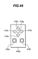
- the operator is able to move the cursor 3080 using an operating portion 470A shown in Fig. 44.
- the operating portion 470A is the same as the operating portion 470 shown in Fig. 2 except that a decision key 470g is additionally provided at the center of the arrow keys 470a, 470b, 470c, 470d. Arrows indicated in the arrow keys 470a, 470b, 470c, 470d correspond to respective directions in which the cursor 3080 is moved.
- the cursor 3080 is positioned in the sub-screen 4002 as described above.
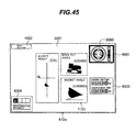
- the cursor 3080 is moved to the sub-screen 4001 as shown in Fig. 45.
- the displayed screen image is changed as shown in Fig. 41. Specifically, the main screen 3001 is changed to the main screen 3002.
- the sub-screen 4002 that has been so far displayed is changed to the sub-screen 4005, the sub-screen 4001 disappears, and the sub-screen 4006 appears. Further, the cursor 3080 is moved to the sub-screen 4005.
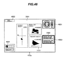
- the cursor 3080 is moved to the sub-screen 4003 as shown in Fig. 46.
- the screen image is changed as shown in Fig. 42.
- the main screen 3001 is changed to the main screen 3003.
- the sub-screen 4002 that has been so far displayed is changed to the sub-screen 4007, the sub-screen 4003 disappears, and the sub-screen 4006 appears. Further, the cursor 3080 is moved to the sub-screen 4007.
- the cursor 3080 is moved to the sub-screen 4004 as shown in Fig. 47.
- the screen image is changed as shown in Fig. 43. Specifically, the main screen 3001 is changed to the main screen 3004.
- the sub-screen 4002 that has been so far displayed is changed to the sub-screen 4008, the sub-screen 4004 disappears, and the sub-screen 4006 appears. Further, the cursor 3080 is moved to the sub-screen 4008.
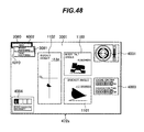
- Fig. 48 shows a state after shifting to the sub-category (hierarchy 2) of the category B from the screen image of Fig. 40 in which the body attitude information of the category B is displayed on the main screen 3001.
- the screen image is changed, as shown in Fig. 48, such that a menu screen 4010 for the sub-categories appears in a partly overlapped relation to the sub-screen 4002.
- the menu screen 4010 has two items "Bucket Monitoring” and "Front Monitoring". "Bucket Monitoring” corresponds to the information of the bucket attitude and body attitude 1100, 1101, 1102 that are currently displayed on the main screen 3001.
- “Front Monitoring” corresponds to the information of the working device attitude 1103 shown in Fig. 16. Further, a sub-cursor 3081 is positioned at the item “Bucket Monitoring" to indicate that the body attitude information currently displayed on the main screen 3001 is the information of the bucket attitude and body attitude 1100, 1101, 1102.
- the screen image is changed as shown in Fig. 50. Specifically, the menu screen 4010 for the sub-categories disappears, and only the sub-screen 4002 is displayed. Comparing Fig. 50 with Fig. 40, the body attitude information displayed on the main screen 3001 is changed from the bucket attitude and body attitude information 1100, 1101, 1102 to the working device attitude information 1103.
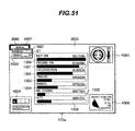
- Fig. 51 shows a state after shifting to the sub-category (hierarchy 2) of the category C from the screen image of Fig. 42 in which the working information (working time information) of the category C is displayed on the main screen 3003.
- the screen image is changed, as shown in Fig. 51, such that a menu screen 4020 for the sub-categories (hierarchy 2) appears in a partly overlapped relation to the sub-screen 4007.
- the menu screen 4020 has two items "Accumulated Working Time” and "Frequency Distribution Table".
- "Accumulated Working Time” corresponds to the respective information of the key-on time 1300, the engine-on time 1301, the excavation time 1302, the travel time 1303, the swing time 1304, the ML crane operating time 1305, and the attachment operating time 1306 that are currently displayed on the main screen 3003.
- “Frequency Distribution Table” corresponds to the respective information of the engine revolution speed frequency distribution 1307, the cooling water temperature frequency distribution 1308, the hydraulic fluid temperature frequency distribution 1309, the excavation load frequency distribution 1310, and the pump load frequency distribution 1311 that are shown in Figs. 18 to 22.
- the sub-cursor 3081 is positioned at the item "Accumulated Working Time” to indicate that the working information currently displayed on the main screen 3003 is the accumulated working time information 1300 to 1306.
- a symbolic illustration 87 for operation guide is displayed at the item "Frequency Distribution Table", and is designed in imitation of the leftward key arrow 470d on the operating portion 470A.
- a menu screen 4030 for lower sub-categories appears on the right side of the item "Frequency Distribution Table” in the menu screen 4020.
- the menu screen 4030 has items "Engine Revolution Speed”, “Water Temperature”, “Hydraulic Fluid Temperature”, “Excavation Load”, and “Pump Load”. These items correspond respectively to the engine revolution speed frequency distribution 1307, the cooling water temperature frequency distribution 1308, the hydraulic fluid temperature frequency distribution 1309, the excavation load frequency distribution 1310, and the pump load frequency distribution 1311 that are shown in Figs. 18 to 22.
- the sub-cursor 3082 is positioned at the item "Engine Revolution Speed” to indicate that the frequency distribution table displayed on the main screen 3003 is the engine revolution speed frequency distribution 1307.
- the screen image is changed as shown in Fig. 55. Specifically, the menu screen 4030 for lower sub-categories of the hierarchy 3 disappears, and the sub-screen 4007 and the menu screen 4020 for the hierarchy 2 are displayed. Comparing Fig. 55 with Fig. 52, the working information displayed on the main screen 3003 is changed from the engine revolution speed frequency distribution 1307 to the hydraulic fluid temperature frequency distribution 1309.
- the screen image is changed as shown in Fig. 56. Specifically, the menu screen 4020 for the sub-categories disappears, and only the sub-screen 4007 is displayed. Comparing Fig. 56 with Fig. 42, the working information displayed on the main screen 3003 is changed to the hydraulic fluid temperature frequency distribution 1309 from the respective information of the key-on time 1300, the engine-on time 1301, the excavation time 1302, the travel time 1303, the swing time 1304, the ML crane operating time 1305, and the attachment operating time 1306.
- This fourth embodiment having the above-described construction can also provide the similar advantages to those obtainable with the first and second embodiments.
- the sub-screens 4002, 4005, 4007, 4008 each displaying the name of the information category, for which information is displayed in detail in corresponding one of the main screens 3001 to 3004, are always displayed in the same upper left position of the screen image
- the sub-screens 4001, 4003, 4004, 4006 each displaying the information in the simplified form, other than the information category, for which information is displayed in detail in corresponding one of the main screens 3001 to 3004, are always displayed in the same respective positions for every category.
- display positions of those sub-screens may be changed as appropriate. For example, when the screen image of Fig. 54 is changed to the screen image of Fig.
- the sub-screen 4006 displaying the body attitude information of the category B in the simplified form may be displayed in the position at which the sub-screen 4001 displaying the meter information of the category A in the simplified form has been so far displayed. Alternatively, it may be displayed in a place where a free widest space is available in the entirety of the screen image, after seeking such a place.
- positions of the sub-screens 4001 to 4008 may be moved with proper combination of key manipulations made on the operating portion 470A in a like manner to dragging common in computer operations.
- the plurality of sub-screens are provided respectively corresponding to the plurality of information categories A, B, C, D.
- the sub-screen corresponding to the information category for which information is displayed in detail in the main screen, is mainly intended to display the name of the information category, only character information may be displayed instead of displaying the sub-screen in the form of a rimmed box.
- plural kinds of information can be displayed in a combined and selective manner, and an operator is able to confirm the information with higher efficiency.
Landscapes
- Engineering & Computer Science (AREA)
- General Engineering & Computer Science (AREA)
- Mining & Mineral Resources (AREA)
- Civil Engineering (AREA)
- Structural Engineering (AREA)
- Theoretical Computer Science (AREA)
- Automation & Control Theory (AREA)
- Mechanical Engineering (AREA)
- Human Computer Interaction (AREA)
- Physics & Mathematics (AREA)
- General Physics & Mathematics (AREA)
- Component Parts Of Construction Machinery (AREA)
Applications Claiming Priority (3)
| Application Number | Priority Date | Filing Date | Title |
|---|---|---|---|
| JP2000363745 | 2000-11-29 | ||
| JP2000363745 | 2000-11-29 | ||
| PCT/JP2001/010372 WO2002044480A1 (fr) | 2000-11-29 | 2001-11-28 | Dispositif d'affichage d'informations pour machine de chantier |
Publications (3)
| Publication Number | Publication Date |
|---|---|
| EP1342853A1 true EP1342853A1 (fr) | 2003-09-10 |
| EP1342853A4 EP1342853A4 (fr) | 2009-04-15 |
| EP1342853B1 EP1342853B1 (fr) | 2012-03-14 |
Family
ID=18834805
Family Applications (1)
| Application Number | Title | Priority Date | Filing Date |
|---|---|---|---|
| EP01998692A Expired - Lifetime EP1342853B1 (fr) | 2000-11-29 | 2001-11-28 | Dispositif d'affichage d'informations pour engin de chantier |
Country Status (6)
| Country | Link |
|---|---|
| US (1) | US6826465B2 (fr) |
| EP (1) | EP1342853B1 (fr) |
| JP (1) | JP3869794B2 (fr) |
| KR (1) | KR100522374B1 (fr) |
| CN (1) | CN1249308C (fr) |
| WO (1) | WO2002044480A1 (fr) |
Cited By (2)
| Publication number | Priority date | Publication date | Assignee | Title |
|---|---|---|---|---|
| GB2405136A (en) * | 2003-08-19 | 2005-02-23 | Komatsu Mfg Co Ltd | Construction machine with efficiency monitor |
| KR20170131483A (ko) * | 2015-03-27 | 2017-11-29 | 스미토모 겐키 가부시키가이샤 | 쇼벨 |
Families Citing this family (53)
| Publication number | Priority date | Publication date | Assignee | Title |
|---|---|---|---|---|
| US20040200644A1 (en) * | 2003-04-08 | 2004-10-14 | Alan Paine | Safe load lifting measurement device |
| JP3902168B2 (ja) * | 2003-09-04 | 2007-04-04 | 日立建機株式会社 | 建設機械の診断情報表示システム |
| US7010367B2 (en) * | 2003-10-16 | 2006-03-07 | Caterpillar Inc. | Operator interface for a work machine |
| US7480869B2 (en) * | 2003-10-31 | 2009-01-20 | International Business Machines Corporation | Method and apparatus for displaying status of hierarchical operations |
| JP4310632B2 (ja) * | 2003-11-07 | 2009-08-12 | 日立建機株式会社 | 建設機械の表示装置 |
| JP4079113B2 (ja) * | 2004-04-19 | 2008-04-23 | 日立建機株式会社 | 建設機械の表示装置 |
| JP4074615B2 (ja) * | 2004-11-17 | 2008-04-09 | 日立建機株式会社 | 建設機械の診断情報表示システム |
| US7441189B2 (en) * | 2005-06-20 | 2008-10-21 | Navico International Limited | Instrumentation interface display customization |
| US7580781B2 (en) * | 2005-12-14 | 2009-08-25 | Clark Equipment Company | Diagnostic system for a power machine |
| JP4853921B2 (ja) * | 2007-02-14 | 2012-01-11 | キャタピラー エス エー アール エル | 機体診断システム |
| JP4847913B2 (ja) * | 2007-03-30 | 2011-12-28 | 日立建機株式会社 | 作業機械周辺監視装置 |
| US7729835B2 (en) * | 2007-08-21 | 2010-06-01 | Jcb Compact Products Limited | Method of controlling a working machine |
| CN101784411A (zh) * | 2007-09-11 | 2010-07-21 | 夏普株式会社 | 仪表面板图像形成装置、仪表面板图像形成方法、车辆、仪表面板图像显示装置、仪表面板图像显示方法、仪表面板图像形成程序、存储有仪表面板图像形成程序的计算机可读取的存储介质 |
| KR100934947B1 (ko) * | 2007-10-02 | 2010-01-06 | 볼보 컨스트럭션 이키프먼트 홀딩 스웨덴 에이비 | 레벨링 수단이 구비된 중장비의 영상표시 시스템 |
| US7810260B2 (en) * | 2007-12-21 | 2010-10-12 | Caterpillar Trimble Control Technologies Llc | Control system for tool coupling |
| JP4700077B2 (ja) * | 2008-03-26 | 2011-06-15 | 株式会社クボタ | 作業機の表示装置 |
| US20090283068A1 (en) * | 2008-05-15 | 2009-11-19 | William L Willison | Fuel filter assembly with pressure sending unit |
| US7936261B2 (en) * | 2008-09-26 | 2011-05-03 | Caterpillar Inc. | System and method for testing a machine using an interactive test script |
| JP5215204B2 (ja) * | 2009-01-29 | 2013-06-19 | 株式会社クボタ | 作業機の表示構造 |
| JP5054833B2 (ja) * | 2011-02-22 | 2012-10-24 | 株式会社小松製作所 | 油圧ショベルの表示システム及びその制御方法 |
| USD704202S1 (en) * | 2011-02-28 | 2014-05-06 | Hitachi Construction Machinery Co., Ltd. | Construction machine display with graphic user interface |
| US8977441B2 (en) | 2011-06-28 | 2015-03-10 | Caterpillar Inc. | Method and system for calculating and displaying work tool orientation and machine using same |
| US9371629B2 (en) | 2011-12-15 | 2016-06-21 | Volvo Construction Equipment Ab | Good-efficiency RPM zone display device for construction machinery |
| EP2796623B1 (fr) * | 2011-12-21 | 2017-03-15 | Volvo Construction Equipment AB | Appareil pour établir un degré d'aptitude à la commande pour un engin de chantier |
| US20130304331A1 (en) * | 2012-05-10 | 2013-11-14 | Caterpillar, Inc. | Display-Based Control for Motor Grader |
| DE102012014655A1 (de) * | 2012-07-24 | 2014-03-06 | Bomag Gmbh | Bedieneinheit für eine Baumaschine und Verfahren zum Betreiben der Bedieneinheit |
| DE102012107550A1 (de) * | 2012-08-17 | 2014-05-15 | Claas Selbstfahrende Erntemaschinen Gmbh | Anzeigenvorrichtung für Landmaschinen |
| JP5624101B2 (ja) * | 2012-10-05 | 2014-11-12 | 株式会社小松製作所 | 掘削機械の表示システム、掘削機械及び掘削機械の表示用コンピュータプログラム |
| KR20140078354A (ko) * | 2012-12-17 | 2014-06-25 | 삼성전자주식회사 | 디스플레이 장치 및 이의 ui 제공 방법 |
| CN103148882B (zh) * | 2013-01-09 | 2018-01-09 | 华东理工大学 | 一种物理参量测量值的复合指示方法 |
| KR101979029B1 (ko) * | 2013-01-23 | 2019-05-15 | 두산인프라코어 주식회사 | 건설장비의 연비 표시 장치 |
| JP5906209B2 (ja) * | 2013-03-15 | 2016-04-20 | Kyb株式会社 | 作業機の制御装置 |
| JP6073170B2 (ja) | 2013-03-27 | 2017-02-01 | 住友建機株式会社 | ショベル |
| US9575628B2 (en) * | 2013-03-29 | 2017-02-21 | Deere & Company | Icon featured touch screen display system including status shortcuts for a work vehicle and method of managing the same |
| JP6284302B2 (ja) * | 2013-04-02 | 2018-02-28 | 株式会社タダノ | ブームの伸縮パターン選択装置 |
| US9050891B2 (en) * | 2013-07-25 | 2015-06-09 | Visteon Global Technologies, Inc. | Articulating instrument cluster |
| KR102107246B1 (ko) | 2013-09-23 | 2020-05-06 | 두산인프라코어 주식회사 | 건설기계의 엔진회전수 비상제어 장치 및 방법 |
| JP6675975B2 (ja) * | 2014-04-25 | 2020-04-08 | 住友建機株式会社 | 建設機械及び建設機械の制御方法 |
| USD781890S1 (en) * | 2014-10-31 | 2017-03-21 | Auto Meter Products, Inc. | Display screen or portion thereof with graphical user interface |
| JP6314105B2 (ja) * | 2015-03-05 | 2018-04-18 | 株式会社日立製作所 | 軌道生成装置および作業機械 |
| DE102016012786B4 (de) * | 2016-10-26 | 2026-02-26 | Liebherr-Werk Biberach Gmbh | Fernsteuer-Einrichtung für Kran, Baumaschine und/oder Flurförderzeug |
| JP6825901B2 (ja) * | 2016-12-22 | 2021-02-03 | 株式会社シマノ | 自転車用表示装置 |
| JP6718399B2 (ja) * | 2017-02-21 | 2020-07-08 | 日立建機株式会社 | 作業機械 |
| US20180346301A1 (en) * | 2017-06-05 | 2018-12-06 | Deere & Company | System and method for operator calibrated implement position display |
| EP3543402B1 (fr) | 2018-03-19 | 2025-03-05 | Joseph Vögele AG | Engin de construction permettant de construire ou de travailler une route |
| JP6962841B2 (ja) * | 2018-03-22 | 2021-11-05 | ヤンマーパワーテクノロジー株式会社 | 旋回作業車の表示システム |
| JP7097022B2 (ja) * | 2018-08-31 | 2022-07-07 | コベルコ建機株式会社 | 建設機械 |
| JP7202193B2 (ja) * | 2019-01-18 | 2023-01-11 | 株式会社小松製作所 | 作業機械の制御装置、作業機械、及び作業機械の制御方法 |
| JP7264795B2 (ja) * | 2019-11-21 | 2023-04-25 | 株式会社小松製作所 | 稼働エリア提示装置および稼働エリア提示方法 |
| JP7662360B2 (ja) * | 2021-03-12 | 2025-04-15 | 株式会社小松製作所 | 作業機械および作業機械の傾斜度合い算出方法 |
| JP7186270B1 (ja) * | 2021-08-31 | 2022-12-08 | 日立建機株式会社 | 作業機械 |
| JP2024005169A (ja) * | 2022-06-30 | 2024-01-17 | ヤンマーホールディングス株式会社 | 建設機械の表示制御装置 |
| WO2025134652A1 (fr) * | 2023-12-19 | 2025-06-26 | 株式会社クボタ | Engin de chantier |
Family Cites Families (10)
| Publication number | Priority date | Publication date | Assignee | Title |
|---|---|---|---|---|
| JP2912495B2 (ja) | 1992-04-13 | 1999-06-28 | 新キャタピラー三菱株式会社 | 多機能ディスプレイモニタ装置とその操作方法 |
| JPH05288648A (ja) | 1992-04-13 | 1993-11-02 | Komatsu Ltd | 建設機械の管理モニタ装置 |
| US5854988A (en) * | 1996-06-05 | 1998-12-29 | Topcon Laser Systems, Inc. | Method for controlling an excavator |
| US6275231B1 (en) * | 1997-08-01 | 2001-08-14 | American Calcar Inc. | Centralized control and management system for automobiles |
| JPH1169258A (ja) * | 1997-08-20 | 1999-03-09 | Fujitsu General Ltd | マルチチャンネル表示装置 |
| JP3293762B2 (ja) * | 1997-09-08 | 2002-06-17 | 住友建機製造株式会社 | 建設機械の表示装置 |
| US5956255A (en) * | 1997-09-23 | 1999-09-21 | Case Corporation | Seed planter performance monitor |
| US6039141A (en) * | 1998-02-23 | 2000-03-21 | Case Corporation | Moving operator and display unit |
| JPH11286971A (ja) * | 1998-04-02 | 1999-10-19 | Shin Caterpillar Mitsubishi Ltd | 表示方法および表示装置 |
| JP2000297443A (ja) * | 1999-04-15 | 2000-10-24 | Komatsu Ltd | 建設機械の情報管理装置 |
-
2001
- 2001-11-28 WO PCT/JP2001/010372 patent/WO2002044480A1/fr not_active Ceased
- 2001-11-28 JP JP2002546821A patent/JP3869794B2/ja not_active Expired - Fee Related
- 2001-11-28 EP EP01998692A patent/EP1342853B1/fr not_active Expired - Lifetime
- 2001-11-28 CN CNB01803781XA patent/CN1249308C/zh not_active Expired - Fee Related
- 2001-11-28 KR KR10-2002-7009647A patent/KR100522374B1/ko not_active Expired - Fee Related
- 2001-11-28 US US10/169,934 patent/US6826465B2/en not_active Expired - Lifetime
Cited By (8)
| Publication number | Priority date | Publication date | Assignee | Title |
|---|---|---|---|---|
| GB2405136A (en) * | 2003-08-19 | 2005-02-23 | Komatsu Mfg Co Ltd | Construction machine with efficiency monitor |
| GB2405136B (en) * | 2003-08-19 | 2008-03-12 | Komatsu Mfg Co Ltd | Construction machine |
| US7395870B2 (en) | 2003-08-19 | 2008-07-08 | Komatsu Ltd. | Construction machine with fuel use indication |
| US7571775B2 (en) | 2003-08-19 | 2009-08-11 | Komatsu Ltd. | Construction machine |
| KR20170131483A (ko) * | 2015-03-27 | 2017-11-29 | 스미토모 겐키 가부시키가이샤 | 쇼벨 |
| EP3276089A4 (fr) * | 2015-03-27 | 2018-04-25 | Sumitomo (S.H.I.) Construction Machinery Co., Ltd. | Pelle |
| US10280597B2 (en) | 2015-03-27 | 2019-05-07 | Sumitomo(S.H.I)Construction Machinery Co., Ltd. | Shovel |
| KR102476122B1 (ko) | 2015-03-27 | 2022-12-08 | 스미토모 겐키 가부시키가이샤 | 쇼벨 |
Also Published As
| Publication number | Publication date |
|---|---|
| US20030001750A1 (en) | 2003-01-02 |
| KR20020076268A (ko) | 2002-10-09 |
| WO2002044480A1 (fr) | 2002-06-06 |
| JPWO2002044480A1 (ja) | 2004-04-02 |
| EP1342853A4 (fr) | 2009-04-15 |
| EP1342853B1 (fr) | 2012-03-14 |
| CN1395642A (zh) | 2003-02-05 |
| US6826465B2 (en) | 2004-11-30 |
| JP3869794B2 (ja) | 2007-01-17 |
| CN1249308C (zh) | 2006-04-05 |
| KR100522374B1 (ko) | 2005-10-18 |
Similar Documents
| Publication | Publication Date | Title |
|---|---|---|
| EP1342853B1 (fr) | Dispositif d'affichage d'informations pour engin de chantier | |
| US6766600B2 (en) | Display device and display controller of construction machinery | |
| JP7216549B2 (ja) | ショベル | |
| EP3666979B1 (fr) | Dispositif d'affichage pour une pelleteuse, et pelleteuse et procédé d'affichage associées | |
| US11525244B2 (en) | Display device for shovel | |
| EP3351692B1 (fr) | Pelle | |
| JP2002275949A (ja) | 建設機械の情報表示装置及び表示制御装置 | |
| KR20200130331A (ko) | 쇼벨 | |
| US20130035824A1 (en) | Display device for construction machine | |
| US20060200283A1 (en) | Construction machine diagnosis information presenting device, diagnosis information display system, and diagnosis information presenting method | |
| EP2634316B1 (fr) | Véhicule de travail | |
| JP7771240B2 (ja) | 作業機械用表示制御システム、作業機械用表示システム、作業機械、作業機械用表示制御方法及び作業機械用表示制御プログラム | |
| KR100673501B1 (ko) | 건설 기계의 표시 장치 | |
| JP2025083390A (ja) | 作業機械の制御方法、作業機械用制御プログラム、作業機械用制御システム及び作業機械 | |
| JPH09268603A (ja) | 建設機械の遠隔操作装置 | |
| EP4299845A1 (fr) | Dispositif de commande d'affichage pour engin de chantier | |
| JP7735163B2 (ja) | 作業機械の制御方法、作業機械用制御プログラム、作業機械用制御システム及び作業機械 |
Legal Events
| Date | Code | Title | Description |
|---|---|---|---|
| PUAI | Public reference made under article 153(3) epc to a published international application that has entered the european phase |
Free format text: ORIGINAL CODE: 0009012 |
|
| 17P | Request for examination filed |
Effective date: 20020710 |
|
| AK | Designated contracting states |
Kind code of ref document: A1 Designated state(s): AT BE CH CY DE DK ES FI FR GB GR IE IT LI LU MC NL PT SE TR |
|
| RBV | Designated contracting states (corrected) |
Designated state(s): AT BE CH CY DE DK FR GB IT LI NL SE |
|
| A4 | Supplementary search report drawn up and despatched |
Effective date: 20090313 |
|
| RIC1 | Information provided on ipc code assigned before grant |
Ipc: B66C 23/90 20060101ALI20090309BHEP Ipc: E02F 9/26 20060101AFI20020613BHEP |
|
| 17Q | First examination report despatched |
Effective date: 20090710 |
|
| GRAP | Despatch of communication of intention to grant a patent |
Free format text: ORIGINAL CODE: EPIDOSNIGR1 |
|
| RTI1 | Title (correction) |
Free format text: INFORMATION DISPLAY DEVICE FOR A CONSTRUCTION MACHINE |
|
| GRAS | Grant fee paid |
Free format text: ORIGINAL CODE: EPIDOSNIGR3 |
|
| GRAA | (expected) grant |
Free format text: ORIGINAL CODE: 0009210 |
|
| AK | Designated contracting states |
Kind code of ref document: B1 Designated state(s): DE FR GB IT NL SE |
|
| RBV | Designated contracting states (corrected) |
Designated state(s): DE FR GB IT NL SE |
|
| REG | Reference to a national code |
Ref country code: GB Ref legal event code: FG4D |
|
| RIN2 | Information on inventor provided after grant (corrected) |
Inventor name: WATANABE, HIROSHI Inventor name: OGURA, HIROSHI Inventor name: SAKYOU, TSUYOSHI Inventor name: ADACHI, HIROYUKI Inventor name: ISHIMOTO, HIDEFUMI |
|
| REG | Reference to a national code |
Ref country code: DE Ref legal event code: R096 Ref document number: 60146269 Country of ref document: DE Effective date: 20120510 |
|
| REG | Reference to a national code |
Ref country code: NL Ref legal event code: VDEP Effective date: 20120314 |
|
| PG25 | Lapsed in a contracting state [announced via postgrant information from national office to epo] |
Ref country code: SE Free format text: LAPSE BECAUSE OF FAILURE TO SUBMIT A TRANSLATION OF THE DESCRIPTION OR TO PAY THE FEE WITHIN THE PRESCRIBED TIME-LIMIT Effective date: 20120314 |
|
| PLBE | No opposition filed within time limit |
Free format text: ORIGINAL CODE: 0009261 |
|
| STAA | Information on the status of an ep patent application or granted ep patent |
Free format text: STATUS: NO OPPOSITION FILED WITHIN TIME LIMIT |
|
| PG25 | Lapsed in a contracting state [announced via postgrant information from national office to epo] |
Ref country code: NL Free format text: LAPSE BECAUSE OF FAILURE TO SUBMIT A TRANSLATION OF THE DESCRIPTION OR TO PAY THE FEE WITHIN THE PRESCRIBED TIME-LIMIT Effective date: 20120314 |
|
| 26N | No opposition filed |
Effective date: 20121217 |
|
| PG25 | Lapsed in a contracting state [announced via postgrant information from national office to epo] |
Ref country code: IT Free format text: LAPSE BECAUSE OF FAILURE TO SUBMIT A TRANSLATION OF THE DESCRIPTION OR TO PAY THE FEE WITHIN THE PRESCRIBED TIME-LIMIT Effective date: 20120314 |
|
| REG | Reference to a national code |
Ref country code: DE Ref legal event code: R097 Ref document number: 60146269 Country of ref document: DE Effective date: 20121217 |
|
| REG | Reference to a national code |
Ref country code: FR Ref legal event code: ST Effective date: 20130731 |
|
| PG25 | Lapsed in a contracting state [announced via postgrant information from national office to epo] |
Ref country code: FR Free format text: LAPSE BECAUSE OF NON-PAYMENT OF DUE FEES Effective date: 20121130 |
|
| PGFP | Annual fee paid to national office [announced via postgrant information from national office to epo] |
Ref country code: GB Payment date: 20131127 Year of fee payment: 13 |
|
| GBPC | Gb: european patent ceased through non-payment of renewal fee |
Effective date: 20141128 |
|
| PG25 | Lapsed in a contracting state [announced via postgrant information from national office to epo] |
Ref country code: GB Free format text: LAPSE BECAUSE OF NON-PAYMENT OF DUE FEES Effective date: 20141128 |
|
| PGFP | Annual fee paid to national office [announced via postgrant information from national office to epo] |
Ref country code: DE Payment date: 20151125 Year of fee payment: 15 |
|
| REG | Reference to a national code |
Ref country code: DE Ref legal event code: R119 Ref document number: 60146269 Country of ref document: DE |
|
| PG25 | Lapsed in a contracting state [announced via postgrant information from national office to epo] |
Ref country code: DE Free format text: LAPSE BECAUSE OF NON-PAYMENT OF DUE FEES Effective date: 20170601 |