EP1342873A2 - Dispositif de verrouillage pour fenêtres et/ou portes - Google Patents
Dispositif de verrouillage pour fenêtres et/ou portes Download PDFInfo
- Publication number
- EP1342873A2 EP1342873A2 EP03000980A EP03000980A EP1342873A2 EP 1342873 A2 EP1342873 A2 EP 1342873A2 EP 03000980 A EP03000980 A EP 03000980A EP 03000980 A EP03000980 A EP 03000980A EP 1342873 A2 EP1342873 A2 EP 1342873A2
- Authority
- EP
- European Patent Office
- Prior art keywords
- housing
- frame
- locking device
- locking
- locking bolt
- Prior art date
- Legal status (The legal status is an assumption and is not a legal conclusion. Google has not performed a legal analysis and makes no representation as to the accuracy of the status listed.)
- Withdrawn
Links
- 238000006073 displacement reaction Methods 0.000 claims description 3
- 239000000463 material Substances 0.000 description 3
- 230000003287 optical effect Effects 0.000 description 3
- 240000007817 Olea europaea Species 0.000 description 2
- 238000006243 chemical reaction Methods 0.000 description 2
- 238000004140 cleaning Methods 0.000 description 2
- 238000009434 installation Methods 0.000 description 2
- 239000007769 metal material Substances 0.000 description 2
- 238000009423 ventilation Methods 0.000 description 2
- 238000004512 die casting Methods 0.000 description 1
- 239000005357 flat glass Substances 0.000 description 1
- 238000000034 method Methods 0.000 description 1
- 238000003825 pressing Methods 0.000 description 1
- 238000007665 sagging Methods 0.000 description 1
- 238000003860 storage Methods 0.000 description 1
Images


Classifications
-
- E—FIXED CONSTRUCTIONS
- E05—LOCKS; KEYS; WINDOW OR DOOR FITTINGS; SAFES
- E05F—DEVICES FOR MOVING WINGS INTO OPEN OR CLOSED POSITION; CHECKS FOR WINGS; WING FITTINGS NOT OTHERWISE PROVIDED FOR, CONCERNED WITH THE FUNCTIONING OF THE WING
- E05F7/00—Accessories for wings not provided for in other groups of this subclass
- E05F7/06—Devices for taking the weight of the wing, arranged away from the hinge axis
-
- E—FIXED CONSTRUCTIONS
- E05—LOCKS; KEYS; WINDOW OR DOOR FITTINGS; SAFES
- E05B—LOCKS; ACCESSORIES THEREFOR; HANDCUFFS
- E05B9/00—Lock casings or latch-mechanism casings ; Fastening locks or fasteners or parts thereof to the wing
-
- E—FIXED CONSTRUCTIONS
- E05—LOCKS; KEYS; WINDOW OR DOOR FITTINGS; SAFES
- E05C—BOLTS OR FASTENING DEVICES FOR WINGS, SPECIALLY FOR DOORS OR WINDOWS
- E05C1/00—Fastening devices with bolts moving rectilinearly
- E05C1/02—Fastening devices with bolts moving rectilinearly without latching action
- E05C1/06—Fastening devices with bolts moving rectilinearly without latching action with operating handle or equivalent member moving otherwise than rigidly with the bolt
-
- E—FIXED CONSTRUCTIONS
- E05—LOCKS; KEYS; WINDOW OR DOOR FITTINGS; SAFES
- E05C—BOLTS OR FASTENING DEVICES FOR WINGS, SPECIALLY FOR DOORS OR WINDOWS
- E05C9/00—Arrangements of simultaneously actuated bolts or other securing devices at well-separated positions on the same wing
- E05C9/06—Arrangements of simultaneously actuated bolts or other securing devices at well-separated positions on the same wing with three or more sliding bars
- E05C9/063—Arrangements of simultaneously actuated bolts or other securing devices at well-separated positions on the same wing with three or more sliding bars extending along three or more sides of the wing or frame
- E05C9/066—Locks for windows or doors specially adapted for tilt and turn
-
- E—FIXED CONSTRUCTIONS
- E05—LOCKS; KEYS; WINDOW OR DOOR FITTINGS; SAFES
- E05C—BOLTS OR FASTENING DEVICES FOR WINGS, SPECIALLY FOR DOORS OR WINDOWS
- E05C9/00—Arrangements of simultaneously actuated bolts or other securing devices at well-separated positions on the same wing
- E05C9/10—Actuating mechanisms for bars
- E05C9/12—Actuating mechanisms for bars with rack and pinion mechanism
-
- E—FIXED CONSTRUCTIONS
- E05—LOCKS; KEYS; WINDOW OR DOOR FITTINGS; SAFES
- E05B—LOCKS; ACCESSORIES THEREFOR; HANDCUFFS
- E05B15/00—Other details of locks; Parts for engagement by bolts of fastening devices
- E05B15/0006—Devices for aligning wing and frame; Anti-rattling devices
-
- E—FIXED CONSTRUCTIONS
- E05—LOCKS; KEYS; WINDOW OR DOOR FITTINGS; SAFES
- E05B—LOCKS; ACCESSORIES THEREFOR; HANDCUFFS
- E05B35/00—Locks for use with special keys or a plurality of keys ; keys therefor
- E05B35/008—Locks for use with special keys or a plurality of keys ; keys therefor for simple tool-like keys
-
- E—FIXED CONSTRUCTIONS
- E05—LOCKS; KEYS; WINDOW OR DOOR FITTINGS; SAFES
- E05B—LOCKS; ACCESSORIES THEREFOR; HANDCUFFS
- E05B63/00—Locks or fastenings with special structural characteristics
- E05B63/0004—Additional locks added to existing lock arrangements
-
- E—FIXED CONSTRUCTIONS
- E05—LOCKS; KEYS; WINDOW OR DOOR FITTINGS; SAFES
- E05B—LOCKS; ACCESSORIES THEREFOR; HANDCUFFS
- E05B63/00—Locks or fastenings with special structural characteristics
- E05B63/04—Locks or fastenings with special structural characteristics for alternative use on the right-hand or left-hand side of wings
-
- E—FIXED CONSTRUCTIONS
- E05—LOCKS; KEYS; WINDOW OR DOOR FITTINGS; SAFES
- E05C—BOLTS OR FASTENING DEVICES FOR WINGS, SPECIALLY FOR DOORS OR WINDOWS
- E05C5/00—Fastening devices with bolts moving otherwise than only rectilinearly and only pivotally or rotatively
- E05C5/02—Fastening devices with bolts moving otherwise than only rectilinearly and only pivotally or rotatively both moving axially and turning about their axis to secure the wing
-
- E—FIXED CONSTRUCTIONS
- E05—LOCKS; KEYS; WINDOW OR DOOR FITTINGS; SAFES
- E05D—HINGES OR SUSPENSION DEVICES FOR DOORS, WINDOWS OR WINGS
- E05D15/00—Suspension arrangements for wings
- E05D15/48—Suspension arrangements for wings allowing alternative movements
- E05D15/52—Suspension arrangements for wings allowing alternative movements for opening about a vertical as well as a horizontal axis
- E05D15/526—Safety devices
-
- E—FIXED CONSTRUCTIONS
- E05—LOCKS; KEYS; WINDOW OR DOOR FITTINGS; SAFES
- E05Y—INDEXING SCHEME ASSOCIATED WITH SUBCLASSES E05D AND E05F, RELATING TO CONSTRUCTION ELEMENTS, ELECTRIC CONTROL, POWER SUPPLY, POWER SIGNAL OR TRANSMISSION, USER INTERFACES, MOUNTING OR COUPLING, DETAILS, ACCESSORIES, AUXILIARY OPERATIONS NOT OTHERWISE PROVIDED FOR, APPLICATION THEREOF
- E05Y2900/00—Application of doors, windows, wings or fittings thereof
- E05Y2900/10—Application of doors, windows, wings or fittings thereof for buildings or parts thereof
- E05Y2900/13—Type of wing
- E05Y2900/132—Doors
-
- E—FIXED CONSTRUCTIONS
- E05—LOCKS; KEYS; WINDOW OR DOOR FITTINGS; SAFES
- E05Y—INDEXING SCHEME ASSOCIATED WITH SUBCLASSES E05D AND E05F, RELATING TO CONSTRUCTION ELEMENTS, ELECTRIC CONTROL, POWER SUPPLY, POWER SIGNAL OR TRANSMISSION, USER INTERFACES, MOUNTING OR COUPLING, DETAILS, ACCESSORIES, AUXILIARY OPERATIONS NOT OTHERWISE PROVIDED FOR, APPLICATION THEREOF
- E05Y2900/00—Application of doors, windows, wings or fittings thereof
- E05Y2900/10—Application of doors, windows, wings or fittings thereof for buildings or parts thereof
- E05Y2900/13—Type of wing
- E05Y2900/148—Windows
Definitions
- the invention relates to a locking device for windows and / or doors, with a housing that can be fastened to a casement, in which a locking bolt is guided, which can be moved for locking in the direction of a locking plate that can be fastened to a frame.
- Such locking devices are used, among other things, in windows of public buildings such as schools and hospitals, in which on the one hand ventilation of the rooms should be possible by tilting the windows, but on the other hand, opening the windows for security reasons is not permitted. In these cases, however, a rotation opening of the windows must be guaranteed for authorized persons with special opening means, for example for cleaning the outer window surfaces.
- DE 101 08 177 A1 discloses a locking device with a locking bolt which is guided in a housing and which can be engaged in a striking plate, the housing and the striking plate being fastened to the inside of the window on the casement frame or on the frame. In the locked state, this prevents the window from turning, but tilting is possible.
- the locking device is opened via separate opening means which are only available to authorized persons.
- a disadvantage of such a locking device is that it affects the optical lines of the window due to the attachment in the visible area of the casement or the window frame.
- an attachment for space reasons is not possible.
- a headstock is known from DE 82 18 086 U1, which is arranged in the lower rebate area of the window and raises the sash again into its predetermined closed position when the sash is pivoted into the frame level.
- the invention has for its object to develop a locking device of the type mentioned in such a way that it affects the optical lines of the window as little as possible, and that they are also used in windows in which the space between the sash lower edge and the window sill is very small can.
- the housing has at least one stop means with which it can be positioned in a rebate space between the lower cross leg of the casement and the window frame in the direction of a flap and / or the casement. Due to the stop means formed on the housing, a secure provisional one is provided during the assembly of the locking device on the window before final fastening Positioning guaranteed. Since the orientation with respect to the sash flap and / or the sash frame takes place, the locking device can be attached longitudinally displaceably at any point along the longitudinal axis of the lower transverse leg of the sash frame, preferably, of course, in the vicinity of the striking plate which is already present. In particular, the positioning is largely independent of the design of the fitting installed in the casement.
- the locking device is prevented from tilting by the stop means and the flow of force between the locking device and the sash is evened out. Due to the positioning in the rebate, the locking device is no longer visible from the inside of the window and therefore does not interfere with the optical lines of the window. The case that the installation space between the sash lower edge and the window sill is very small is no longer disadvantageous due to the changed installation position within the rebate space.
- the housing has a first and a second stop means formed on the housing in the form of stop faces, the stop means being oriented at right angles to one another and the first stop means for positioning in relation to the surface of the wing flap facing the rebate area and the second stop means can be used for positioning relative to the lower cross leg of the casement.
- the one-piece connection of the sling means to the housing means that they can be molded directly out of the housing without great design effort.
- the design as an essentially flat abutment surface has the advantage that the housing contours are necessary anyway only minor adjustments or orientations to each other can be used functionally in addition to their housing function.
- first and second stop means Due to the right-angled arrangement of the first and second stop means to each other, these are precisely adapted to the contour of the sash frame in the rebate space, since there is usually a corresponding angle of 90 ° between the lower cross leg of the sash frame and the surface of the sash flap facing the rebate space.
- the housing has bores for receiving screws and can be supported and screwed to the sash overlap via the first attachment means, the housing on the sash frame and / or on one connected to the sash frame Espagnolette fitting can be supported with the second lifting means.
- the screw connection between the locking device and the wing flap can take place in such a way that the screws are carried out from the side of the rebate space through the holes in the housing with the flap flap or other components connected to it.
- a screw connection directly to the casement frame or even a screw connection through an elongated hole in the connecting rod fitting is not necessary.
- the housing only lies loosely on the sash frame or the connecting rod fitting and can be supported against it when force is applied.
- the locking bolt is drive-connected to a handle shaft and can be actuated via this by an operating element which is connected to the handle shaft, the longitudinal axis of the handle shaft being perpendicular to Longitudinal axis of the locking bolt is located and wherein the handle shaft can be passed through an opening of the flap.
- the handle shaft serves as a connecting link between the locking bolt and the control element. Since the locking bolt with the housing is located in the rebate space and the control element must be arranged on the window side facing the interior of the room, the opening in the wing flap serves to connect these two components, the handle shaft being passed through the opening.
- the locking bolt is rotatably mounted in the housing about an axis of rotation lying transversely to its longitudinal axis and is connected in one piece to the handle shaft such that the axis of rotation of the locking bolt coincides with the longitudinal axis of the handle shaft.
- a rotatably mounted locking bolt integrates the mounting of the locking bolt and the mounting of the handle shaft, thereby reducing the number of bearing points in the housing.
- the locking bolt is guided longitudinally in the housing along its longitudinal axis and the drive connection between the locking bolt and the handle shaft takes place via a toothing, wherein the handle shaft has a circular external toothing and the locking bolt has a straight toothing area. Due to the longitudinal guide, one is opposite the rotary bearing somewhat more complex storage, an overall more space-efficient design is possible since, due to the longitudinal guidance, no swivel space outside the housing is required for the otherwise rotatably mounted locking bolt and this can now be moved directly in the direction of the striking plate.
- the external toothing of the handle shaft and the straight, rack-like toothed area of the locking bolt enables the rotary movement of the handle shaft, which is initiated by the operating element, to be converted into a straight-line movement of the locking bolt in the direction of the striking plate.
- the housing is formed in one piece with an opening on opposite sides in each case for the implementation of the locking bolt, with the locking bolt optionally being able to be guided through one of the openings to ensure left / right usability.
- the left / right usability results from the changed mounting orientation of the locking bolt within the housing, and simple swapping is also possible after the locking device has been installed by removing the locking bolt and inserting it into the other opening.
- control element is mounted in a control element receptacle connected to the wing flap and is spring-loaded displaceable in the direction of the longitudinal axis of the handle shaft, and that the control element is a tool receptacle for an operating tool for longitudinal displacement and rotation and has a locking device for locking in at least one end position in the connection area with the control element receptacle, the control element being screwable to the housing, and the screws can be guided through holes in the flap.
- the housing has a run-up surface for the run-up on a frame area, the run-up surface having a flat support area for holding the sash frame firmly in relation to the frame and a lifting area which is angled and / or rounded off to raise the Sash frame compared to the frame.
- the locking device Due to the ramp surface integrated on the housing side, the locking device fulfills the function of a ramp block solely because of its shape and without additional components, in addition to its locking function and thus reduces the assembly effort due to the reduction of individual parts.
- the support area keeps the sash evenly in the closed position when the window is closed, while the lifting area causes a uniform lifting from the sagged position into the closed position during the pivoting movement of the sash frame into the frame.
- the lifting area can either be wedge-shaped with a surface that is only rounded with respect to the run-up surface or convexly rounded for a non-linear lifting movement.
- the ramp surface in the lifting area and / or support area has at least one rotatable roller to reduce the friction with the frame area. This reduces the friction between the contact surface and the frame area and also simplifies handling for the user, and also reduces wear.
- the housing is designed in two parts with a first housing part and a second housing part and in the assembled state has openings on opposite sides for the implementation of the locking bolt, the length of the locking bolt in the longitudinal direction being greater than the length of the case.
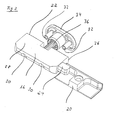
- Fig. 1 shows a door or a window 10 in a sectional view, as it can be installed in a masonry of a house, not shown, and can be equipped with a window glass pane, also not shown.
- the window 10 consists, inter alia, of a fixed frame 12 and a sash frame 14 which is rotatable and / or tiltable relative thereto.
- a locking device 16 is attached within the rebate space 15 between the sash frame and the frame Interior of the house facing side - arranged control element 18, which is arranged on the flap 17, is driven.
- the sash 14 has a groove 19 into which a drive rod fitting, not shown, can be inserted.
- the locking device 16 can be used, inter alia, in windows of public buildings such as schools and hospitals, in which on the one hand ventilation of the rooms should be possible by tilting the windows, but on the other hand opening the windows for security reasons is not permitted. In these cases, however, a rotation opening of the windows must be guaranteed for authorized persons with special opening means, for example for cleaning the outside window surfaces from inside the room.
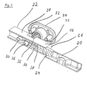
- a housing 22 of the locking element 16 is connected to the casement 14 and the striking plate 20 to the frame 12.
- the housing 22 is produced as a one-piece metallic component, for example by a die-casting process.
- a locking bolt 24 is guided in a longitudinally displaceable manner in the housing 22 and can be moved for locking in the direction of the locking plate 20 and can reach behind it for closing.
- the housing is equipped with a first stop means 26 and a second stop means 28, the first stop means 26 for positioning relative to the sash flap 17 and the second stop means 28 for positioning relative to the lower transverse leg of the sash frame 14 is.
- forces which are introduced, for example, via the striking plate 20 onto the locking device 16 are transmitted to the sash frame via the stop means 26 and 28.
- this is provided with bores 30 for receiving screws, not shown, which can be inserted through the housing and screwed with a thread 32 of an operating element receptacle 34.
- the housing 22 is supported against the wing overlap 17 via the stop means 26 and screwed via the screws, whereas it is only loosely supported against the wing frame 14 via the stop means 28.
- the locking bolt 24 is drive-connected to a handle shaft 36, the handle shaft having external teeth.
- the locking bolt 24 has a straight toothing region 38 which can be brought into engagement with the toothing of the handle shaft 36 and thus converts a rotation of the handle shaft 36 into a translational movement of the locking bolt 24.
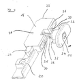
- the handle shaft 36 is driven via the control element 18 visible in FIG. 4, which is received by the control element receptacle 34.
- the handle shaft 36 as can be seen in FIG. 1, is guided through an opening 35 in the flap.
- the operating element 18 can be displaced spring-loaded within the operating element receptacle 34 by a spring 40, the spring pressing the operating element with the operating element stop edge 42 against the operating element receiving stop edge 44 and holding it in this position.
- an operating tool not shown, which can be inserted into a tool holder 46 of the operating element 18, the operating element can be displaced into the interior of the operating element holder 34 against the spring force.
- Tooth 48 which is designed to correspond to the toothing of the handle shaft 36, ensures longitudinal displaceability.
- the rotation of the control element 18 about the longitudinal axis of the handle shaft 36 also causes the handle shaft 36 to rotate via the toothing 48, which in turn leads to a displacement of the locking bolt 24.
- the rotary movement of the operating element 18 can be fixed in end positions offset by 180 ° by the latching device 50 which can be seen in FIG. 4.
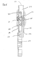
- the housing 16 is made in one piece and has an opening 52 and 54 on opposite sides in each case.
- a housing channel 56 is formed within the housing 16, in which the locking bolt 24 is guided.
- the locking bolt 24 it is possible to arrange the locking bolt 24 within the housing 16 in such a way that it emerges from the housing 16 either through the opening 52 or through the opening 54. A right / left usability of the locking device 16 is thus ensured by simply changing the locking bolt 24.
- the sash 14 is rotatable relative to the frame 12 about the axis of rotation 58 or tiltable about the tilt axis 60.
- the locking device is not immediately recognizable in FIG. 8, which shows the window seen from the interior of the room, since it is arranged in the rebate space 15 between the lower cross leg 62 of the casement 14 and the frame 12. Only the control element receptacle 34 and the control element 18 can be seen from the interior of the room. 8 shows the function of the locking device 16 on the window 10.
- the sash frame 14 can be rotated about the axis of rotation 58 or tilted about the tilting axis 60 via the handle olive 64 and a drive rod system 66 connected thereto with respect to the frame 12.
- the closed state of the locking device 16 that is, when the locking bolt 24 engages behind the striking plate 20, as corresponds to the illustration in FIG. 2, the casement 14 can be tilted further with respect to the frame 12.
- the handle olive 64 is brought into the rotational position and the drive rod system 66 releases the sash frame 14 for rotation
- the locking device 16 blocks the sash frame 14 by engaging the striking plate 20 with the locking bolt 24.
- the locking device 16 is therefore first closed to open.
- a separate operating tool is required, so that the sash frame 14 can only be opened by authorized persons.
- the locking device 16 can be expanded by an overrun function.
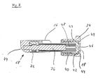
- the housing 22 has a run-up surface 68 which can be seen in FIG. 7 and which runs onto a run-up area 70 of the frame 12 which is visible in FIG. 1.
- the run-up surface consists of a support area 72 for holding the sash frame 14 in a fixed position relative to the frame and a lifting area 74 rounded off by this for lifting the sash frame 14 against the frame 12. The lifting takes place when the sash frame 14 is pivoted into the plane of the frame 12.
- the run-up area 70 can be part of the frame or consist of an auxiliary component connected to it.
- the auxiliary component can in turn consist of a metallic material.
- a cover for the housing 22, at least in the run-up area 70, which is likewise made of a plastic material, can alternatively be provided in order to reduce the wear.
- FIG. 9 shows an alternative embodiment of the locking device with a housing consisting of two housing halves 23a, 23b.
- the locking bolt 25 is longer than the housing 23, which can be seen in FIG. 9 by the fact that it is flush on the right housing side and on the left housing side in the possibility of engagement with the striking plate, not shown, over the housing survives.
- the striking plate should be to the right of the housing in FIG. 9, no conversion measures are required on the locking device, but only a different switching position is present for locking.
Landscapes
- Engineering & Computer Science (AREA)
- Mechanical Engineering (AREA)
- Wing Frames And Configurations (AREA)
- Door And Window Frames Mounted To Openings (AREA)
- Window Of Vehicle (AREA)
- Lock And Its Accessories (AREA)
Applications Claiming Priority (2)
| Application Number | Priority Date | Filing Date | Title |
|---|---|---|---|
| DE20203809U | 2002-03-08 | ||
| DE20203809U DE20203809U1 (de) | 2002-03-08 | 2002-03-08 | Verriegelungsvorrichtung für Fenster und/oder Türen |
Publications (2)
| Publication Number | Publication Date |
|---|---|
| EP1342873A2 true EP1342873A2 (fr) | 2003-09-10 |
| EP1342873A3 EP1342873A3 (fr) | 2006-05-24 |
Family
ID=7968775
Family Applications (1)
| Application Number | Title | Priority Date | Filing Date |
|---|---|---|---|
| EP03000980A Withdrawn EP1342873A3 (fr) | 2002-03-08 | 2003-01-17 | Dispositif de verrouillage pour fenêtres et/ou portes |
Country Status (3)
| Country | Link |
|---|---|
| EP (1) | EP1342873A3 (fr) |
| DE (1) | DE20203809U1 (fr) |
| PL (1) | PL358829A1 (fr) |
Cited By (1)
| Publication number | Priority date | Publication date | Assignee | Title |
|---|---|---|---|---|
| EP2620572A2 (fr) | 2012-01-26 | 2013-07-31 | Aug. Winkhaus GmbH & Co. KG | Dispositif de verrouillage pour le blocage d'un mouvement d'un battant par rapport à un cadre |
Families Citing this family (1)
| Publication number | Priority date | Publication date | Assignee | Title |
|---|---|---|---|---|
| DE102010063678A1 (de) * | 2010-12-21 | 2012-06-21 | Aug. Winkhaus Gmbh & Co. Kg | Treibstangenbeschlag für ein Dreh-/Kippfenster mit einer Ausstellschere |
Citations (2)
| Publication number | Priority date | Publication date | Assignee | Title |
|---|---|---|---|---|
| DE8218086U1 (de) | 1982-06-24 | 1982-09-23 | Wilh. Frank Gmbh, 7022 Leinfelden-Echterdingen | Auflaufbock fuer den fluegel eines fensters, einer tuer od. dgl. |
| DE10108177A1 (de) | 2000-03-22 | 2001-09-27 | Winkhaus Fa August | Dreh-Kipp-Fenster mit Stellantrieb zum Kippöffnen |
Family Cites Families (7)
| Publication number | Priority date | Publication date | Assignee | Title |
|---|---|---|---|---|
| US3469875A (en) * | 1967-11-06 | 1969-09-30 | Amerock Corp | Latching assembly |
| NL174857C (nl) * | 1974-07-31 | 1984-08-16 | Herpen Frederik Cornelis Van | Afdichting voor twee paneelvormige elementen. |
| GB2129864B (en) * | 1982-10-30 | 1986-07-23 | Donald Malcolm Fullard | Door or window fasteners |
| WO1994021877A1 (fr) * | 1993-03-25 | 1994-09-29 | Fankhauser, Peter | Installation de securite pour elements de fermeture d'un acces |
| GB2279984A (en) * | 1993-07-16 | 1995-01-18 | Heywood Williams Ltd | Window securement arrangement |
| GB2297794B (en) * | 1995-02-10 | 1998-12-30 | Hoong Thye Eldon Lee | Closure mechanism for airtight doors |
| DE29604643U1 (de) * | 1996-03-13 | 1996-05-15 | Rittal-Werk Rudolf Loh Gmbh & Co Kg, 35745 Herborn | Schaltschrank mit Rahmengestell und Tür mit Schubstangenverschluß |
-
2002
- 2002-03-08 DE DE20203809U patent/DE20203809U1/de not_active Expired - Lifetime
-
2003
- 2003-01-17 EP EP03000980A patent/EP1342873A3/fr not_active Withdrawn
- 2003-02-20 PL PL03358829A patent/PL358829A1/xx not_active Application Discontinuation
Patent Citations (2)
| Publication number | Priority date | Publication date | Assignee | Title |
|---|---|---|---|---|
| DE8218086U1 (de) | 1982-06-24 | 1982-09-23 | Wilh. Frank Gmbh, 7022 Leinfelden-Echterdingen | Auflaufbock fuer den fluegel eines fensters, einer tuer od. dgl. |
| DE10108177A1 (de) | 2000-03-22 | 2001-09-27 | Winkhaus Fa August | Dreh-Kipp-Fenster mit Stellantrieb zum Kippöffnen |
Cited By (2)
| Publication number | Priority date | Publication date | Assignee | Title |
|---|---|---|---|---|
| EP2620572A2 (fr) | 2012-01-26 | 2013-07-31 | Aug. Winkhaus GmbH & Co. KG | Dispositif de verrouillage pour le blocage d'un mouvement d'un battant par rapport à un cadre |
| DE102012201127A1 (de) | 2012-01-26 | 2013-08-01 | Aug. Winkhaus Gmbh & Co. Kg | Sperreinrichtung zur Sperrung einer Bewegung eines gegen einen Rahmen bewegbaren Flügels |
Also Published As
| Publication number | Publication date |
|---|---|
| EP1342873A3 (fr) | 2006-05-24 |
| DE20203809U1 (de) | 2002-05-16 |
| PL358829A1 (en) | 2003-09-22 |
Similar Documents
| Publication | Publication Date | Title |
|---|---|---|
| EP3702562B1 (fr) | Ferrure de fixation ainsi qu'agencement de ferrure et agencement de cadre et de battant | |
| DE102016111564A1 (de) | Stangenschloss | |
| DE68903724T2 (de) | Beschlag fuer tuer, fenster oder dergleichen. | |
| EP0204991B1 (fr) | Dispositif pour arrêter un châssis de battant tournant autour d'un pivot par rapport à une chambranle | |
| DE3022163A1 (de) | Dreh-kipp-beschlag fuer fenster, tueren o.dgl. mit spaltlueftung | |
| DE19858709A1 (de) | Scharnier, insbesondere für Türflügel von Duschabtrennungen | |
| DE3004854C2 (de) | Feststellvorrichtung für Flügel von Fenstern, Türen o.dgl. in wenigstens einer Spaltlüftungsstellung | |
| DE102015120712A1 (de) | Fenster zum Verschließen einer Gebäudeöffnung | |
| EP1342873A2 (fr) | Dispositif de verrouillage pour fenêtres et/ou portes | |
| CH690504A5 (de) | Scharniervorrichtung und Laufwerk für dreh- und verschiebbare Flügelelemente. | |
| EP4707515A2 (fr) | Fermeture à charnière | |
| EP0837210B1 (fr) | Coordinateur d'ouverture des portes à double battants | |
| EP0199270B1 (fr) | Dispositif pour maintenir une porte ou une fenêtre entrouverte dans au moins une position | |
| EP1614844A2 (fr) | Dispositif d'articulation | |
| DE20102570U1 (de) | Drehkippbeschlag | |
| EP1176276A1 (fr) | Structure de verrouillage autoverrouillable avec possibilité de réglage | |
| EP1503015A2 (fr) | Verrou de blocage en basculement pour fenêtre | |
| DE10301046B4 (de) | Drehbeschlag für die verdeckte Anordnung an Türen oder Fenstern | |
| EP0674075A1 (fr) | Ferrure de pivotement | |
| DE19909365A1 (de) | Vorrichtung zum Feststellen und Verriegeln von Türen oder Wandelementen | |
| EP0189814B1 (fr) | Dispositif pour maintenir en position ouverte un volet de fenêtre ou de porte | |
| EP1405974B1 (fr) | Mécanisme de verrouillage pour fenêtre ou porte oscillobattante | |
| AT502965B1 (de) | Vorrichtung zur regelung der öffnungsfolge von zweiflügeligen schwenktüren | |
| EP0495198A1 (fr) | Arrêt de porte, notamment pour fenêtre oscillo battante | |
| DE29818045U1 (de) | Beschlag für Klappfenster, insbesondere von Wohnwagen, Mobilheimen u.dgl. |
Legal Events
| Date | Code | Title | Description |
|---|---|---|---|
| PUAI | Public reference made under article 153(3) epc to a published international application that has entered the european phase |
Free format text: ORIGINAL CODE: 0009012 |
|
| AK | Designated contracting states |
Kind code of ref document: A2 Designated state(s): AT BE BG CH CY CZ DE DK EE ES FI FR GB GR HU IE IT LI LU MC NL PT SE SI SK TR |
|
| AX | Request for extension of the european patent |
Extension state: AL LT LV MK RO |
|
| PUAL | Search report despatched |
Free format text: ORIGINAL CODE: 0009013 |
|
| AK | Designated contracting states |
Kind code of ref document: A3 Designated state(s): AT BE BG CH CY CZ DE DK EE ES FI FR GB GR HU IE IT LI LU MC NL PT SE SI SK TR |
|
| AX | Request for extension of the european patent |
Extension state: AL LT LV MK RO |
|
| AKX | Designation fees paid |
Designated state(s): AT BE BG CH CY CZ DE DK EE ES FI FR GB GR HU IE IT LI LU MC NL PT SE SI SK TR |
|
| STAA | Information on the status of an ep patent application or granted ep patent |
Free format text: STATUS: THE APPLICATION IS DEEMED TO BE WITHDRAWN |
|
| 18D | Application deemed to be withdrawn |
Effective date: 20061125 |