EP1342922A2 - Druckspeicher - Google Patents
Druckspeicher Download PDFInfo
- Publication number
- EP1342922A2 EP1342922A2 EP03001475A EP03001475A EP1342922A2 EP 1342922 A2 EP1342922 A2 EP 1342922A2 EP 03001475 A EP03001475 A EP 03001475A EP 03001475 A EP03001475 A EP 03001475A EP 1342922 A2 EP1342922 A2 EP 1342922A2
- Authority
- EP
- European Patent Office
- Prior art keywords
- piston
- main piston
- pressure accumulator
- pressure
- auxiliary
- Prior art date
- Legal status (The legal status is an assumption and is not a legal conclusion. Google has not performed a legal analysis and makes no representation as to the accuracy of the status listed.)
- Granted
Links
- 239000012530 fluid Substances 0.000 claims abstract description 29
- 238000007789 sealing Methods 0.000 claims description 48
- 230000009969 flowable effect Effects 0.000 claims description 10
- 238000011118 depth filtration Methods 0.000 claims description 8
- 230000006835 compression Effects 0.000 claims description 5
- 238000007906 compression Methods 0.000 claims description 5
- 238000013022 venting Methods 0.000 claims 1
- 238000001914 filtration Methods 0.000 abstract description 3
- 239000007788 liquid Substances 0.000 abstract description 3
- 239000003795 chemical substances by application Substances 0.000 description 4
- 238000010276 construction Methods 0.000 description 4
- 238000011109 contamination Methods 0.000 description 4
- 239000000463 material Substances 0.000 description 4
- 239000003921 oil Substances 0.000 description 4
- 239000000835 fiber Substances 0.000 description 3
- 230000036316 preload Effects 0.000 description 3
- 230000001133 acceleration Effects 0.000 description 2
- 230000000694 effects Effects 0.000 description 2
- 229920001971 elastomer Polymers 0.000 description 2
- 239000000806 elastomer Substances 0.000 description 2
- 230000007774 longterm Effects 0.000 description 2
- 238000004519 manufacturing process Methods 0.000 description 2
- 239000002923 metal particle Substances 0.000 description 2
- 238000012856 packing Methods 0.000 description 2
- 239000000126 substance Substances 0.000 description 2
- 238000009825 accumulation Methods 0.000 description 1
- 230000015572 biosynthetic process Effects 0.000 description 1
- 230000007123 defense Effects 0.000 description 1
- 230000006735 deficit Effects 0.000 description 1
- 230000001419 dependent effect Effects 0.000 description 1
- 238000006073 displacement reaction Methods 0.000 description 1
- 239000004744 fabric Substances 0.000 description 1
- 230000002349 favourable effect Effects 0.000 description 1
- 238000009950 felting Methods 0.000 description 1
- 239000010720 hydraulic oil Substances 0.000 description 1
- 230000001788 irregular Effects 0.000 description 1
- 238000013508 migration Methods 0.000 description 1
- 230000005012 migration Effects 0.000 description 1
- 239000004745 nonwoven fabric Substances 0.000 description 1
- 239000002245 particle Substances 0.000 description 1
- 230000000717 retained effect Effects 0.000 description 1
- 238000000926 separation method Methods 0.000 description 1
- 238000009423 ventilation Methods 0.000 description 1
Images
Classifications
-
- F—MECHANICAL ENGINEERING; LIGHTING; HEATING; WEAPONS; BLASTING
- F15—FLUID-PRESSURE ACTUATORS; HYDRAULICS OR PNEUMATICS IN GENERAL
- F15B—SYSTEMS ACTING BY MEANS OF FLUIDS IN GENERAL; FLUID-PRESSURE ACTUATORS, e.g. SERVOMOTORS; DETAILS OF FLUID-PRESSURE SYSTEMS, NOT OTHERWISE PROVIDED FOR
- F15B1/00—Installations or systems with accumulators; Supply reservoir or sump assemblies
- F15B1/02—Installations or systems with accumulators
- F15B1/04—Accumulators
- F15B1/08—Accumulators using a gas cushion; Gas charging devices; Indicators or floats therefor
- F15B1/24—Accumulators using a gas cushion; Gas charging devices; Indicators or floats therefor with rigid separating means, e.g. pistons
-
- F—MECHANICAL ENGINEERING; LIGHTING; HEATING; WEAPONS; BLASTING
- F15—FLUID-PRESSURE ACTUATORS; HYDRAULICS OR PNEUMATICS IN GENERAL
- F15B—SYSTEMS ACTING BY MEANS OF FLUIDS IN GENERAL; FLUID-PRESSURE ACTUATORS, e.g. SERVOMOTORS; DETAILS OF FLUID-PRESSURE SYSTEMS, NOT OTHERWISE PROVIDED FOR
- F15B2201/00—Accumulators
- F15B2201/20—Accumulator cushioning means
- F15B2201/205—Accumulator cushioning means using gas
-
- F—MECHANICAL ENGINEERING; LIGHTING; HEATING; WEAPONS; BLASTING
- F15—FLUID-PRESSURE ACTUATORS; HYDRAULICS OR PNEUMATICS IN GENERAL
- F15B—SYSTEMS ACTING BY MEANS OF FLUIDS IN GENERAL; FLUID-PRESSURE ACTUATORS, e.g. SERVOMOTORS; DETAILS OF FLUID-PRESSURE SYSTEMS, NOT OTHERWISE PROVIDED FOR
- F15B2201/00—Accumulators
- F15B2201/20—Accumulator cushioning means
- F15B2201/21—Accumulator cushioning means using springs
-
- F—MECHANICAL ENGINEERING; LIGHTING; HEATING; WEAPONS; BLASTING
- F15—FLUID-PRESSURE ACTUATORS; HYDRAULICS OR PNEUMATICS IN GENERAL
- F15B—SYSTEMS ACTING BY MEANS OF FLUIDS IN GENERAL; FLUID-PRESSURE ACTUATORS, e.g. SERVOMOTORS; DETAILS OF FLUID-PRESSURE SYSTEMS, NOT OTHERWISE PROVIDED FOR
- F15B2201/00—Accumulators
- F15B2201/30—Accumulator separating means
- F15B2201/31—Accumulator separating means having rigid separating means, e.g. pistons
- F15B2201/312—Sealings therefor, e.g. piston rings
-
- F—MECHANICAL ENGINEERING; LIGHTING; HEATING; WEAPONS; BLASTING
- F15—FLUID-PRESSURE ACTUATORS; HYDRAULICS OR PNEUMATICS IN GENERAL
- F15B—SYSTEMS ACTING BY MEANS OF FLUIDS IN GENERAL; FLUID-PRESSURE ACTUATORS, e.g. SERVOMOTORS; DETAILS OF FLUID-PRESSURE SYSTEMS, NOT OTHERWISE PROVIDED FOR
- F15B2201/00—Accumulators
- F15B2201/30—Accumulator separating means
- F15B2201/32—Accumulator separating means having multiple separating means, e.g. with an auxiliary piston sliding within a main piston, multiple membranes or combinations thereof
-
- F—MECHANICAL ENGINEERING; LIGHTING; HEATING; WEAPONS; BLASTING
- F15—FLUID-PRESSURE ACTUATORS; HYDRAULICS OR PNEUMATICS IN GENERAL
- F15B—SYSTEMS ACTING BY MEANS OF FLUIDS IN GENERAL; FLUID-PRESSURE ACTUATORS, e.g. SERVOMOTORS; DETAILS OF FLUID-PRESSURE SYSTEMS, NOT OTHERWISE PROVIDED FOR
- F15B2201/00—Accumulators
- F15B2201/40—Constructional details of accumulators not otherwise provided for
- F15B2201/41—Liquid ports
- F15B2201/411—Liquid ports having valve means
-
- F—MECHANICAL ENGINEERING; LIGHTING; HEATING; WEAPONS; BLASTING
- F15—FLUID-PRESSURE ACTUATORS; HYDRAULICS OR PNEUMATICS IN GENERAL
- F15B—SYSTEMS ACTING BY MEANS OF FLUIDS IN GENERAL; FLUID-PRESSURE ACTUATORS, e.g. SERVOMOTORS; DETAILS OF FLUID-PRESSURE SYSTEMS, NOT OTHERWISE PROVIDED FOR
- F15B2201/00—Accumulators
- F15B2201/40—Constructional details of accumulators not otherwise provided for
- F15B2201/41—Liquid ports
- F15B2201/413—Liquid ports having multiple liquid ports
-
- F—MECHANICAL ENGINEERING; LIGHTING; HEATING; WEAPONS; BLASTING
- F15—FLUID-PRESSURE ACTUATORS; HYDRAULICS OR PNEUMATICS IN GENERAL
- F15B—SYSTEMS ACTING BY MEANS OF FLUIDS IN GENERAL; FLUID-PRESSURE ACTUATORS, e.g. SERVOMOTORS; DETAILS OF FLUID-PRESSURE SYSTEMS, NOT OTHERWISE PROVIDED FOR
- F15B2201/00—Accumulators
- F15B2201/40—Constructional details of accumulators not otherwise provided for
- F15B2201/415—Gas ports
- F15B2201/4155—Gas ports having valve means
Definitions
- the invention relates to a pressure accumulator with a piston arrangement which is longitudinally displaceable within a accumulator housing and is formed from a main piston and an auxiliary piston which is movable relative to the latter and which seals a fluid side of the accumulator from its gas side via a sealing device, the latter separating means with depth filtration properties, further sealing elements and the like has a chamber adjacent to the inner wall of the storage housing for a flowable sealing medium which can be pretensioned by the auxiliary piston which is acted upon by the pressure of the gas side and the force of an energy accumulator for a relative movement which reduces the volume of the chamber.
- a pressure accumulator is known with a cylinder tube as the accumulator housing, two pistons being longitudinally displaceable as a separating element between a working gas located on one side and the working medium located on the opposite side of the accumulator housing, preferably in the form of hydraulic oil.
- One piston in the manner of a main piston has an inner bore and the further second piston in the manner of an auxiliary piston can be guided therein with a part corresponding in diameter to the diameter of this inner bore and with another part on the cylinder wall of the storage housing.
- There is a sealing medium between the two pistons which has a much higher viscosity than the working medium and preferably consists of fat.
- the sealing medium is biased enclosed between the double piston arrangement in order to achieve an increased seal from the gas to the fluid side of the pressure accumulator.
- the sealing arrangement in question is not suitable, in particular in tough operating conditions, a high degree of contamination, high acceleration forces, low temperatures, in order to meet these requirements.
- the known pressure accumulator solution is large in the axial direction, because the two pistons must have a greater length so that they do not jam in the cylinder tube and additional guidance by a piston rod or the like is not provided.
- a pressure accumulator of this type is already known, see DE 197 40 150 A1.
- pressure accumulators also called piston accumulators
- high demands have to be placed on functionality, namely over wide temperature ranges, for example between minus 40 ° C and plus 150 ° C.
- special attention must be paid to the careful design of the sealing device in order to prevent gas from escaping to the fluid or oil side when there is no pressure on the fluid side.
- the risk must be counteracted that seals of the sealing device, in particular elastomer seals, are damaged or even destroyed by contamination particles.
- a pressure cushion additionally formed on the inner wall of the storage housing flowable sealing medium reduces the risk of gas loss, especially during downtimes, where there is no operating pressure on the fluid side.
- the known solution has a main piston and an auxiliary piston, which are arranged at an axial distance from one another in the storage housing, so that an intermediate space is formed in the form of a chamber which adjoins the inner wall of the storage housing and can be filled with a sealing medium.
- a connecting rod attached to the auxiliary piston passes through the main piston and is displaceably guided therein.
- a spring clamped between the main piston and an end stop of the connecting rod serves as a force accumulator, which attempts to bring the auxiliary piston and the main piston closer together to reduce the volume of the space between them.
- the construction of the piston arrangement from separate pistons with guidance of the auxiliary piston on a connecting rod which can be displaced in the main piston represents, on the one hand, a complex construction and, on the other hand, is unsatisfactory in terms of functional reliability.
- the functional reliability is endangered because of the tight fit of the guide of the connecting rod of the separate pistons even slight deformations can lead to jamming.
- the auxiliary piston which can be moved along the inner wall of the accumulator housing with the main piston, is subject to the same wear load as the main piston.
- the design of the piston assembly with two separate pistons with connecting rod guide is a construction that is neither inexpensive to manufacture nor easy to assemble.
- the object of the invention is to create a pressure accumulator which, although simple and inexpensive to produce, has improved operating behavior, in particular long-term behavior, even under particularly tough operating conditions.
- this object is achieved according to the invention in that the auxiliary piston is guided in a fully integrated manner in a guide of the main piston which is open to the gas side, and in that a space can be enclosed therein by means of the auxiliary piston which forms part of the chamber receiving the flowable sealing medium ,
- the integrated arrangement of the auxiliary piston within the main piston enables particularly cost-effective production and simple assembly. Problems with fits, such as occur with separate pistons and their guidance via a connecting rod, are avoided.
- the auxiliary piston is guided within the main piston according to the invention, it is particularly robust against mechanical loads, so that the pressure accumulator according to the invention is particularly suitable for special fields of application, for example for military applications, for example for use in battle tanks.
- the separating agent with the depth filtration property which forms part of the sealing device, is preferably arranged last on the piston arrangement toward the fluid side, so that fluid migrating from the fluid side to the further sealing elements, for example hydraulic fluid contaminated by metal particles, undergoes depth filtration, so that a Danger to the axially adjoining further sealing elements is avoided.
- a felt in particular in the form of at least one felt ring, is preferably used as the release agent.
- felt stands for a compressed scrim with an irregular arrangement of fibers, in particular natural and chemical fibers.
- Both needle felt and fulled felt can be used, in which the fiber layer similar to the initial wadding is intertwined by means of felting needles with barbs, or in which the nonwovens are strengthened by pressure and movement under heat and moisture.
- Woven felt materials made from woven, milled and felted fabrics can also be used.
- the use of felt materials of relatively high density has proven to be favorable, for example materials with density values in the range of 0.36 g / cm 3 , corresponding to hardness group F2 according to DIN 61200. It goes without saying that, depending on the nature, type of soiling and degree of liquid of the fluid side any suitable filtration materials of other density and / or hardness groups can be selected.
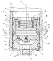
- FIG. 1 shows the fluid-side section of the accumulator housing of the exemplary embodiment of the pressure accumulator according to the invention, with a cylinder tube 1 and a cylinder cover 3 forming the fluid-side closure.
- the latter is fixed at the end of the cylinder tube 1 by means of a split retaining ring 5, which in turn is secured by an annular disk 7 which is screwed to the cylinder cover 3 by means of three screws 9, only one of which is visible in FIG. 1.
- the cylinder cover 3 has a bore 12 concentric with the cylinder axis 11 for the connection of a fluid line.
- the gas-side end of the cylinder tube 3, not shown, is closed by a cylinder cover, which has fittings, such as a gas filling valve, in the manner customary in such pressure accumulators.
- a sealing packing is also provided on the cylinder cover (not shown) at the gas-side end of the cylinder tube 1.
- a piston arrangement is guided so as to be longitudinally displaceable along the axis 11.
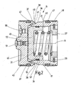
- This piston arrangement which is shown separately in FIG. 2 and is designated as a whole by 15, is formed from a main piston 17 and an auxiliary piston 19, the latter being movably guided in a guide 21 which extends in the main piston 17 concentrically with the axis 11 and to the gas side 23 on the right-hand side in FIG. 1 is open.
- the piston arrangement 15 formed from the main piston 17 and auxiliary piston 19 separates the gas side, designated 23, from the fluid side, designated 25 in FIG. 1, which is connected to the fluid connection 12 within the cylinder tube 1.
- the guide 21 of the main piston 17 is delimited by an annular body 27 which is axially secured by a locking ring 29.
- the auxiliary piston 19 located in the guide 21 of the main piston 17 is secured against exiting from the guide 21 by abutment on the annular body 27.
- Fig. 1 shows the piston position of the auxiliary piston 19, in which it rests on the ring body 27.
- the auxiliary piston 19 is trough-shaped, a helical compression spring 33 being seated in the interior 31 which is concentric with the longitudinal axis 11 and which is supported on the one hand on the bottom of the interior 31 and on the other hand on the annular body 27.
- the compression spring 33 serving as an energy store on the auxiliary piston 19 generates a pretensioning force for a movement to the left, corresponding to the viewing direction of FIGS. 1 and 2, ie for the movement in one direction that reduces corresponds to the volume of the space 35 located between the auxiliary piston 19 and the closed end of the guide 21 in the main piston 17.
- the space 35 which, as will be explained in more detail below, is provided for accommodating a flowable sealing medium, forms part of a chamber which adjoins the inner wall of the cylinder tube 1 in order to form a pressure cushion from the sealing medium which bears against this inner wall.
- the space 35 is connected via a plurality of connecting channels 37 to a recess 39 which is machined into the circumference of the main piston 17 and extends in a ring shape over the entire circumference of the main piston 17.
- the axis 41 of the connecting channels 37 extends obliquely to the main longitudinal axis 11.
- the bottom of the recess 39 has a different depth over its axial extent. More precisely, the bottom of the depression 39 has flat and concavely curved bottom surface parts 38 and 40, the opening of the connecting channels 37 in the depression 39 being located in a flat bottom surface part 38, the plane of which extends perpendicular to the axis 41 of the connecting channels 37 ,
- the sealing device which effects the separation between the gas side 23 and the fluid side 35 is formed entirely on the circumference of the main piston 17.
- the sealing device has a separating agent with depth filtration properties, namely in the exemplary embodiment a felt ring 43 which is seated in an annular groove of the main piston 17 in the region of the piston crown 45 forming the end of the inner guide 21.
- a piston seal 47 of the type commonly used in pressure accumulators, for example an elastomer seal, is provided axially offset from the recess 39. Axially offset further to gas side 23 is after recess 39 a further piston seal 47.
- a piston guide strip 49 is provided on the gas-side end region of the main piston 17.
- a filling channel 51 Arranged centrally in the piston crown 45 is a filling channel 51 for introducing the sealing medium into the space 35, which together with the recess 39 forms the chamber for the pressure cushion of the sealing medium lying against the inner wall of the cylinder tube 1 via the connecting channels 37.
- a check valve 53 is located in the filling channel 51.
- a closable vent hole 55 is provided in the piston crown 45.
- the auxiliary piston 19 is sealed off from the guide 21 in the main piston 17 by means of a sealing ring 57.
- a sealing element of simple design can be used here because the seal to be formed is not exposed to great loads during operation, especially since the auxiliary piston 19 practically does not move during operation.
- Fig. 2 shows the piston assembly 15 in a relaxed state, the auxiliary piston 19 being displaced by the force of the compression spring 33 until it abuts the piston crown 45.
- the vent hole 55 is opened and the piston arrangement 15 is inserted into the cylinder tube 1 with the cylinder cover 3 removed.
- the sealing medium intended for use is now filled into the space 35 via the filling channel 51 and the check valve 53 until the state of the ventilation is reached.
- the vent hole 55 is now closed and by further supply of the sealing medium via the check valve 53, a pressure is built up in the space 35 until the auxiliary piston moves against the force of the spring 33 against the ring body 27, such as this is shown in Fig. 1.
- the supply of the sealing medium is now stopped, so that a pressure cushion of the sealing medium is present in the space 35, and thus via the connecting channels 37 in the recess 39, the pressure being dependent on the spring force of the compression spring 33 and in a practical example about 5 Cash amount.
- the storage housing is now closed by attaching the cylinder cover 3.
- the piston seals 47 are both in each case preloaded to the outside with a slight differential pressure, so that dirt cannot penetrate from the outside.
- the piston seals 47 are lubricated by the sealing medium, which is preferably a liquid used on the fluid or oil side.
- the sealing medium is preferably a liquid used on the fluid or oil side.
- practically all flowable substances can be used as the sealing medium, including gas.
- the use of the hydraulic fluid on the fluid side is advantageous because there are no foreign oils in the system.
- a gas preload pressure is now built up on the gas side 23, for example by entering N 2 , a preload pressure of 60 bar being able to be provided in a practical application, then the pressure in the space 35 and in the depression 39 increases in this example to a pressure value of 60 bar plus the pressure generated by the force of the spring 33 by means of the auxiliary piston 19, that is, in the example mentioned, to about 65 bar. Since the pressure in the depression 39 is thus higher than on the gas side 23, there is no migration through Gas is possible via the piston seal 47 closest to the gas side 23.
- the pressure in the accumulator housing increases accordingly, so that the pressure on the gas side 23 increases accordingly, assumed as a game of thought, for example to 150 bar.
- This increases the Pressure in the space 35 containing the sealing medium and in the recess 39 to a pressure value which corresponds to the gas pressure on the gas side 23 plus the pressure generated by the spring 33 on the auxiliary piston 19, that is to say 155 bar in the example mentioned the differential pressure applied to the piston seals 47 is also only about 5 bar, ie in operation, the piston seals 47 are only loaded with the low differential pressure mentioned.
- the pressure accumulator according to the invention has an extremely long service life even under harsh operating conditions.
- the felt ring 43 not only protects the sealing device from contamination, but also protects the subsequent piston seal 47 from pressure surges, since the oil volume sitting behind the felt ring 43 and in front of the subsequent piston seal 47 generates a differential pressure.
- the pressure accumulator according to the invention is protected in particular against gas losses during downtimes, ie in the absence of fluid pressure, because the pressure of the sealing medium prevailing in the space 35 and the recess 39 is always higher than the pressure on the gas side 23.
Landscapes
- Engineering & Computer Science (AREA)
- Physics & Mathematics (AREA)
- Fluid Mechanics (AREA)
- Mechanical Engineering (AREA)
- General Engineering & Computer Science (AREA)
- Supply Devices, Intensifiers, Converters, And Telemotors (AREA)
- Braking Systems And Boosters (AREA)
- Details Of Reciprocating Pumps (AREA)
Abstract
Description
- Die Erfindung bezieht sich auf einen Druckspeicher mit einer innerhalb eines Speichergehäuses längs verfahrbahren, aus Hauptkolben und relativ zu diesem bewegbarem Hilfskolben gebildeten Kolbenanordnung, die eine Fluidseite des Speichers von seiner Gasseite über eine Dichteinrichtung abdichtend trennt, welch letztere ein Trennmittel mit Tiefenfiltrationseigenschaften, weitere Dichtelemente sowie eine an die Innenwand des Speichergehäuses angrenzende Kammer für ein strömungsfähiges Dichtmedium aufweist, das durch den Hilfskolben vorspannbar ist, der für eine das Volumen der Kammer verkleinernde Relativbewegung mit dem Druck der Gasseite und der Kraft eines Kraftspeichers beaufschlagt ist.
- Durch die CH 591 020 A5 ist ein Druckspeicher bekannt mit einem Zylinderrohr als Speichergehäuse, wobei als Trennorgan zwischen einem auf der einen Seite befindlichen Arbeitsgas und dem auf der gegenüberliegenden Seite des Speichergehäuses befindlichen Arbeitsmedium, vorzugsweise in Form von Hydrauliköl, zwei Kolben längsverschiebbar geführt sind. Der eine Kolben in der Art eines Hauptkolbens besitzt eine Innenbohrung und der weitere zweite Kolben in der Art eines Hilfskolbens ist mit einem im Durchmesser dem Durchmesser dieser Innenbohrung entsprechenden Teil in derselben führbar und mit einem anderen Teil an der Zylinderwand des Speichergehäuses. Zwischen den beiden Kolben befindet sich ein Dichtmedium, das eine wesentlich höhere Viskosität aufweist als das Arbeitsmedium und vorzugsweise aus Fett besteht. In Abhängigkeit vom Befüllungs- und Betriebszustand des bekannten Druckspeichers wird das Dichtmedium eingeschlossen zwischen der Doppelkolbenanordnung vorgespannt, um dergestalt eine erhöhte Abdichtung von der Gas- zur Fluidseite des Druckspeichers zu erreichen. Es hat sich jedoch gezeigt, dass insbesondere bei harten Einsatzbedingungen, hoher Verschmutzungsgrad, hohe Beschleunigungskräfte, tiefe Temperaturen etc., die dahingehende Dichtanordnung nicht geeignet ist, um diesen Anforderungen gerecht zu werden. Darüber hinaus baut die bekannte Druckspeicherlösung in axialer Richtung groß auf, denn die beiden Kolben müssen eine größere Länge haben, damit sie sich im Zylinderrohr nicht verkanten und eine zusätzliche Führung durch eine Kolbenstange od. dgl. ist nicht vorgesehen.
- Ein Druckspeicher dieser Art ist bereits bekannt, siehe DE 197 40 150 A1. Für den Einsatz derartiger Druckspeicher, auch Kolbenspeicher genannt, sind an die Funktionstüchtigkeit hohe Anforderungen zu stellen, und zwar über weite Temperaturbereiche, beispielsweise zwischen minus 40°C bis plus 150°C. Um ein zufriedenstellendes Langzeitverhalten derartiger Speicher zu erreichen, muß besonderes Augenmerk auf die sorgfältige Ausbildung der Dichteinrichtung gelegt werden, um ein Entweichen von Gas zur Fluid- oder Ölseite zu vermeiden, wenn auf der Fluidseite kein Druck ansteht. In Verwendungsbereichen, wo auf der Fluidseite eine Verschmutzung entsteht, beispielsweise in Form von Metallpartikeln, wie es bei Getriebekonstruktionen grundsätzlich der Fall ist, muß der Gefahr entgegengewirkt werden, dass Dichtungen der Dichteinrichtung, insbesondere Elastomerdichtungen, durch Verschmutzungspartikel beschädigt oder gar zerstört werden. Durch der Dichteinrichtung zugeordnete Trennmittel mit Tiefenfiltrationseigenschaften soll dieser Gefahr begegnet werden. Ein an der Innenwand des Speichergehäuses zusätzlich ausgebildetes Druckpolster eines strömungsfähigen Dichtmediums verringert die Gefahr von Gasverlusten, insbesondere auch bei Stillstandszeiten, wo auf der Fluidseite kein Betriebsdruck herrscht.
- Als Kolbenanordnung weist die bekannte Lösung einen Haupt- und einen Hilfskolben auf, die im Speichergehäuse in einem axialen Abstand voneinander angeordnet sind, so dass ein Zwischenraum in Form einer an die Innenwand des Speichergehäuses angrenzenden Kammer gebildet wird, die mit einem Dichtmedium befüllbar ist. Eine am Hilfskolben befestigte Verbindungsstange durchgreift den Hauptkolben und ist in diesem verschiebbar geführt. Eine zwischen Hauptkolben und einem Endanschlag der Verbindungsstange eingespannte Feder dient als Kraftspeicher, der Hilfskolben und Hauptkolben zur Verringerung des Volumens des zwischen ihnen befindlichen Raumes einander anzunähern sucht.
- Der Aufbau der Kolbenanordnung aus getrennten Kolben mit Führung des Hilfskolbens an einer im Hauptkolben verschiebbaren Verbindungsstange stellt zum einen eine aufwendige Bauweise dar und ist zum anderen hinsichtlich der Funktionssicherheit wenig zufriedenstellend. Insbesondere bei harten Einsatzbedingungen, wo Unempfindlichkeit gegen mechanische Belastungen, beispielsweise gegen hohe Beschleunigungskräfte, gefordert wird, wie dies insbesondere bei einem Einsatz in Fahrzeugen für wehrtechnische Zweck gefordert wird, ist die Funktionssicherheit gefährdet, weil wegen der engen Passungen der Führung der Verbindungsstange der gesonderten Kolben bereits geringfügige Verformungen zu einem Verklemmen führen können. Der mit dem Hauptkolben längs der Innenwand des Speichergehäuses bewegbare Hilfskolben unterliegt der gleichen Verschleißbelastung wie der Hauptkolben. Auch stellt die Ausbildung der Kolbenanordnung mit zwei gesonderten Kolben mit Verbindungsstangenführung eine Bauweise dar, die weder kostengünstig herstellbar noch einfach montierbar ist.
- Ausgehend von diesem Stand der Technik stellt sich die Erfindung die Aufgabe, einen Druckspeicher zu schaffen, der, obwohl er einfach und kostengünstig herstellbar ist, ein verbessertes Betriebsverhalten, insbesondere Langzeitverhalten, besitzt, selbst bei besonders harten Einsatzbedingungen.
- Bei einem Druckspeicher der Eingangs genannten Art ist diese Aufgabe erfindungsgemäß dadurch gelöst, dass der Hilfskolben vollständig integriert in einer zur Gasseite offenen Führung des Hauptkolbens geführt ist und dass in diesem mittels des Hilfskolbens ein Raum einschließbar ist, der Teil der das strömungsfähige Dichtmedium aufnehmenden Kammer bildet.
- Die integrierte Anordnung des Hilfskolbens innerhalb des Hauptkolbens ermöglicht eine besonders kostengünstige Fertigung und einfache Montage. Probleme mit Passungen, wie sie bei gesonderten Kolben und deren Führung über eine Verbindungsstange auftreten, sind vermieden. Bei der erfindungsgemäß vorgesehenen Führung des Hilfskolbens innerhalb des Hauptkolbens ergibt sich eine besondere Robustheit gegen mechanische Belastungen, so dass der erfindungsgemäße Druckspeicher für spezielle Einsatzgebiete, zum Beispiel für wehrtechnische Anwendungen, in besonders hohem Maße geeignet ist, etwa für eine Verwendung bei Kampfpanzern.
- An die Ausbildung der Abdichtung des Hilfskolbens relativ zu seiner Führung im Hauptkolben sind keinerlei besondere Anforderungen zu stellen, weil im Unterschied zu dem erwähnten, bekannten Druckspeicher der Hilfskolben nicht längs der Innenwand des Speichergehäuses zusammen mit der Bewegung des Hauptkolbens beweglich ist. Eine Beeinträchtigung des Hilfskolbens durch Verschleiß oder durch Schmutz an der Innenwand des Speichergehäuses ist somit ausgeschlossen. Die Standzeit der aus einer einfachen Kolbendichtung bestehenden Abdichtung zwischen Hilfskolben und Führung im Hauptkolben ist außerordentlich lang, weil im Betrieb praktisch keine ins Gewicht fallende Verschiebebewegung zwischen Hilfskolben und Hauptkolben erfolgt. Zudem ist diese Abdichtung zwischen Hilfskolben und Hauptkolben im Betrieb nur durch einen der Vorspannkraft des Kraftspeichers entsprechenden Differenzdruck belastet.
- Vorzugsweise ist das Trennmittel mit der Tiefenfiltrationseigenschaft, welches Teil der Dichteinrichtung bildet, an der Kolbenanordnung zur Fluidseite hin zuletzt angeordnet, so dass von der Fluidseite her zu den weiteren Dichtelementen hin wandernde Flüssigkeit, beispielsweise durch Metallpartikel verschmutzte Hydraulikflüssigkeit, eine Tiefenfilterung erfährt, so dass eine Gefährdung der sich axial anschließenden, weiteren Dichtelemente vermieden ist.
- Als Trennmittel findet bevorzugt ein Filz, insbesondere in Form mindestens eines Filzringes, Verwendung. Filz steht hierbei im Sinne der Erfindung für ein verdichtetes Gelege mit regelloser Anordnung von Fasern, insbesondere von Natur- und Chemiefasern. Es kann sowohl Nadelfilz als auch Walkfilz eingesetzt werden, bei dem die Anfangswatte ähnliche Faserschicht mittels Filznadeln mit Widerhaken verschlungen wird bzw. bei dem Faservliese durch Druck und Bewegung unter Wärme und Feuchtigkeit verfestigt werden. Des weiteren können Webfilzmaterialien eingesetzt werden aus gewebten, gewalkten und verfilzten Stoffen. Als günstig hat sich die Verwendung von Filzmaterialien relativ hoher Dichte erwiesen, etwa Materialien mit Dichtewerten im Bereich von 0,36 g/cm3, entsprechend Härtegruppe F2 nach DIN 61200. Es versteht sich, dass je nach Beschaffenheit, Verschmutzungsart und -grad der Flüssigkeit der Fluidseite beliebige geeignete Filtrationsmaterialien anderer Dichte und/oder Härtegruppen gewählt werden können.
- Nachstehend ist die Erfindung anhand eines in der Zeichnung dargestellten Ausführugnsbeispieles im einzelnen beschrieben. Es zeigen:
- Fig. 1 einen abgebrochen gezeichneten und nur den fluidseitigen Endbereich zeigenden Längsschnitt eines Druckspeichers gemäß einem Ausführungsbeispiel der Erfindung und
- Fig. 2 einen Längsschnitt nur der Kolbenanordnung des Druckspeichers von Fig. 1, wobei die Kolbenanordnung jedoch im Unterschied zu Fig. 1 in entspanntem Zustand gezeigt ist.
- Fig. 1 zeigt den fluidseitigen Abschnitt des Speichergehäuses des Ausführungsbeispieles des erfindungsgemäßen Druckspeichers, mit einem Zylinderrohr 1 und einem den fluidseitigen Abschluß bildenden Zylinderdeckel 3. Letzterer ist am Ende des Zylinderrohres 1 mittels eines geteilten Sicherungsringes 5 fixiert, welcher wiederum durch eine Ringscheibe 7 gesichert ist, die mit dem Zylinderdeckel 3 mittels dreier Schrauben 9 verschraubt ist von denen in Fig. 1 lediglich eine sichtbar ist. Der Zylinderdeckel 3 weist eine zur Zylinderachse 11 konzentrische Bohrung 12 für den Anschluß einer Fluidleitung auf.
- In ähnlicher Weise ist das nicht dargestellte gasseitige Ende des Zylinderrohres 3 durch einen Zylinderdeckel geschlossen, der in der bei derartigen Druckspeichern üblichen Art entsprechende Armaturen, wie ein Gasfüllventil, aufweist.
- Entsprechend der am Zylinderdeckel 3 vorgesehenen, mit 13 bezeichneten Dichtpackung ist auch am nicht dargestellten Zylinderdeckel am gasseitigen Ende des Zylinderrohres 1 eine Dichtpackung vorgesehen.
- Im Zylinderrohr 1, das beim vorliegenden Beispiel kreiszylindrisch ist, ist eine Kolbenanordnung entlang der Achse 11 längs verschiebbar geführt. Diese Kolbenanordnung, die in Fig. 2 gesondert dargestellt und als Ganzes mit 15 bezeichnet ist, ist aus einem Hauptkolben 17 und einem Hilfskolben 19 gebildet, welch letzterer in einer Führung 21 bewegbar geführt ist, welche sich im Hauptkolben 17 konzentrisch zur Achse 11 erstreckt und zu der in Fig. 1 rechtsseitig gelegenen Gasseite 23 hin offen ist. Die aus Hauptkolben 17 und Hilfskolben 19 gebildete Kolbenanordnung 15 trennt innerhalb des Zylinderrohres 1 die mit 23 bezeichnete Gasseite von der in Fig. 1 mit 25 bezeichneten Fluidseite, die mit dem Fluidanschluß 12 in Verbindung ist.
- An dem der Gasseite 23 zugewandten Ende ist die Führung 21 des Hauptkolbens 17 durch einen Ringkörper 27 begrenzt, der durch einen Segerring 29 axial gesichert ist. Der in der Führung 21 des Hauptkolbens 17 befindliche Hilfskolben 19 ist gegen den Austritt aus der Führung 21 durch Anlage am Ringkörper 27 gesichert. Fig. 1 zeigt die Kolbenstellung des Hilfskolbens 19, in der dieser am Ringkörper 27 anliegt. Der Hilfskolben 19 ist trogförmig gestaltet, wobei in dem zur Längsachse 11 konzentrischen Innenraum 31 eine Schrauben-Druckfeder 33 sitzt, die sich einerseits am Boden des Innenraumes 31 und andererseits am Ringkörper 27 abstützt. Zusätzlich zu dem am Hilfskolben 19 wirkenden Druck der Gasseite 23 erzeugt die als Kraftspeicher dienende Druckfeder 33 am Hilfskolben 19 eine Vorspannkraft für eine Bewegung nach links, entsprechend der Blickrichtung der Fig. 1 und 2, d.h. für die Bewegung in einer Richtung, die einer Verringerung des Volumens des Raumes 35 entspricht, der sich zwischen dem Hilfskolben 19 und dem geschlossenen Ende der Führung 21 im Hauptkolben 17 befindet. Der Raum 35, der wie nachstehend näher erläutert wird, für die Aufnahme eines strömungsfähigen Dichtmediums vorgesehen ist, bildet Teil einer Kammer, die an die Innenwand des Zylinderrohres 1 angrenzt, um ein an dieser Innenwand anliegendes Druckpolster aus dem Dichtmedium zu bilden. Zu diesem Zweck ist der Raum 35 über mehrere Verbindungskanäle 37 mit einer in den Umfang des Hauptkolbens 17 eingearbeiteten Vertiefung 39 verbunden, die sich ringförmig über den gesamten Umfang des Hauptkolbens 17 erstreckt. Wie aus den Fig. ersichtlich, verläuft die Achse 41 der Verbindungskanäle 37 zur Hauptlängsachse 11 schräg. Der Boden der Vertiefung 39 weist über seine axiale Erstreckung eine unterschiedliche Tiefe auf. Genauer gesagt weist der Boden der Vertiefung 39 aneinander angrenzende ebene und konkav gewölbte Bodenflächenteile 38 bzw. 40 auf, wobei die Einmündung der Verbindungskanäle 37 in die Vertiefung 39 in einem ebenen Bodenflächenteil 38 gelegen ist, dessen Ebene sich senkrecht zur Achse 41 der Verbindungskanäle 37 erstreckt.
- Die die Trennung zwischen der Gasseite 23 und der Fluidseite 35 bewirkende Dichteinrichtung ist zur Gänze am Umfang des Hauptkolbens 17 ausgebildet. Als der Fluidseite 25 nächstgelegenes Bauelement weist die Dichteinrichtung ein Trennmittel mit Tiefenfiltrationseigenschaften auf, nämlich beim Ausführungsbeispiel einen Filzring 43, der im Bereich des den Abschluß der inneren Führung 21 bildenden Kolbenbodens 45 in einer Ringnut des Hauptkolbens 17 sitzt. Axial gegen die Vertiefung 39 hin versetzt ist eine Kolbendichtung 47 der bei Druckspeichern üblicherweise verwendeten Art vorgesehen, beispielsweise eine Elastomerdichtung. Axial weiter zur Gasseite 23 hin versetzt befindet sich nach der Vertiefung 39 eine weitere Kolbendichtung 47. Schließlich ist am gasseitigen Endbereich des Hauptkolbens 17 eine Kolbenführungsleiste 49 vorgesehen.
- Zentral im Kolbenboden 45 angeordnet befindet sich ein Füllkanal 51 für das Einbringen des Dichtmediums in den Raum 35, der über die Verbindungskanäle 37 zusammen mit der Vertiefung 39 die Kammer für das an der Innenwand des Zylinderrohres 1 anliegende Druckpolster des Dichtmediums bildet. Im Füllkanal 51 befindet sich ein Rückschlagventil 53. Außerdem ist im Kolbenboden 45 eine verschließbare Entlüftungsbohrung 55 vorgesehen.
- Der Hilfskolben 19 ist gegenüber der Führung 21 im Hauptkolben 17 mittels eines Dichtringes 57 abgedichtet. Ein Dichtelement einfacher Bauart kann hier benutzt werden, weil die zu bildende Abdichtung im Betrieb keinen großen Belastungen ausgesetzt ist, zumal im Betrieb praktisch keine Verschiebebewegung des Hilfskolbens 19 erfolgt.
- Nachstehend ist die Funktionsweise des erfindungsgemäßen Druckspeichers näher erläutert. Fig. 2 zeigt die Kolbenanordnung 15 in entspanntem Zustand, wobei der Hilfskolben 19 durch die Kraft der Druckfeder 33 bis zur Anlage am Kolbenboden 45 verschoben ist. Für die Montage des Druckspeichers wird die Entlüftungsbohrung 55 geöffnet und die Kolbenanordnung 15 bei abgenommenem Zylinderdeckel 3 in das Zylinderrohr 1 eingesetzt. Über den Füllkanal 51 und das Rückschlagventil 53 wird nun das zur Verwendung vorgesehene Dichtmedium in den Raum 35 eingefüllt, bis der Zustand der Entlüftung erreicht ist. Die Entlüftungsbohrung 55 wird nun geschlossen und durch weitere Zufuhr des Dichtmediums über das Rückschlagventil 53 ein Druck im Raum 35 aufgebaut, bis sich der Hilfskolben gegen die Kraft der Feder 33 gegen den Ringkörper 27 bewegt, wie dies in Fig. 1 dargestellt ist. Die Zufuhr des Dichtmediums wird nun beendet, so dass im Raum 35, und damit über die Verbindungskanäle 37 in der Vertiefung 39, ein Druckpolster des Dichtmediums vorhanden ist, wobei der Druck von der Federkraft der Druckfeder 33 abhängig ist und bei einem praktischen Beispiel etwa 5 Bar beträgt. Durch Anbringen des Zylinderdekkels 3 wird nun das Speichergehäuse geschlossen.
- Entsprechend dem im Raum 35 und in der Vertiefung 39 herrschenden geringen Druck von beispielsweise 5 Bar sind die Kolbendichtungen 47 beide jeweils nach außen mit einem geringen Differenzdruck vorgespannt, so dass ein Eindringen von Schmutz von außen her nicht möglich ist. Zudem sind die Kolbendichtungen 47 durch das Dichtmedium geschmiert, bei dem es sich vorzugsweise um eine auf der Fluid- oder Ölseite eingesetzte Flüssigkeit handelt. Als Dichtmedium können jedoch praktisch sämtliche strömungsfähigen Stoffe eingesetzt werden, auch Gas. Die Verwendung der auf der Fluidseite vorliegenden Hydraulikflüssigkeit ist jedoch vorteilhaft, weil somit keine Fremdöle im System vorhanden sind.
- Wird auf der Gasseite 23 nunmehr ein Gas-Vorspanndruck aufgebaut, indem beispielsweise N2 eingegeben wird, wobei bei einer praktischen Anwendung beispielsweise ein Vorspanndruck von 60 Bar vorgesehen sein kann, dann erhöht sich der Druck im Raum 35 und in der Vertiefung 39 bei diesem Beispiel auf einen Druckwert von 60 Bar zuzüglich des durch die Kraft der Feder 33 mittels des Hilfskolben 19 erzeugten Druckes, also beim genannten Beispiel auf etwa 65 Bar. Da somit der Druck in der Vertiefung 39 höher ist als auf der Gasseite 23, ist kein Durchwandern von Gas über die der Gasseite 23 nächstgelegene Kolbendichtung 47 möglich.
- Wird der Speicher in Betrieb genommen, also die Fluidseite 25 mit dem Fluiddruck belastet, erhöht sich in entsprechender Weise der Druck im Speichergehäuse, so dass der Druck auf der Gasseite 23 entsprechend steigt, als Gedankenspiel angenommen beispielsweise auf 150 Bar. Dadurch erhöht sich wiederum der Druck in dem das Dichtmedium enthaltenden Raum 35 und in der Vertiefung 39 auf einen Druckwert, der dem Gasdruck auf der Gasseite 23 zuzüglich des durch die Feder 33 am Hilfskolben 19 erzeugten Druckes entspricht, also beim erwähnten Beispiel auf etwa 155 Bar. Dadurch ist der an den Kolbendichtungen 47 anliegende Differenzdruck ebenfalls lediglich etwa 5 Bar, d.h. im Betrieb sind die Kolbendichtungen 47 ausschließlich mit dem erwähnten, geringen Differenzdruck belastet.
- In Zusammenwirkung mit der durch den Filzring 43 bewirkten Filtration des Hydraulikfluides und der geringen Belastung der Kolbendichtungen 47, wie sie durch das Druckpolster des Dichtmediums in der Vertiefung 39 erreicht ist, ergeben sich für den erfindungsgemäßen Druckspeicher außerordentlich lange Standzeiten selbst bei harten Betriebsbedingungen. Der Filzring 43 schützt nicht nur die Dichteinrichtung vor Verunreinigungen, sondern schützt auch die nachfolgende Kolbendichtung 47 vor Druckschlägen, da das in dem hinter dem Filzring 43 und vor der nachfolgenden Kolbendichtung 47 sitzende Ölvolumen einen Differenzdruck erzeugt.
- Der erfindungsgemäße Druckspeicher ist insbesondere gegen Gasverluste bei Stillstandszeiten, d.h. bei fehlendem Fluiddruck, geschützt, weil der in dem Raum 35 und der Vertiefung 39 herrschende Druck des Dichtmediums immer höher ist als der Druck auf der Gasseite 23.
- Selbst wenn nach langer Betriebslebensdauer das Dichtmedium in der Kammer 35 verbraucht worden sein sollte, bleibt die Funktionsfähigkeit des Systems erhalten. In diesem Falle führt ein Durchwandern der der Gasseite 23 nächstgelegenen Kolbendichtung 47 durch das Gas zu einer Ansammlung des Gases im Raum 35. Wird der Druckspeicher nun außer Betrieb gesetzt, indem die Fluidseite 25 drucklos gemacht wird, ergibt sich im Raum 35 aufgrund der auf den Hilfskolben 19 wirkenden Kraft der Feder 33 wieder ein Druckniveau, in diesem Falle ein Gasdruckniveau, das der Federkraftwirkung entsprechend höher ist als der Druck auf der Gasseite 23, so dass auch in diesem Betriebszustand Sicherheit gegen Gasverluste gegeben ist.
Claims (9)
- Druckspeicher-mit einer innerhalb eines Speichergehäuses (1) längs verfahrbaren, aus Hauptkolben (17) und relativ zu diesem bewegbarem Hilfskolben (19) gebildeten Kolbenanordnung (15), die eine Fluidseite (25) des Speichers von seiner Gasseite (23) über eine Dichteinrichtung abdichtend trennt, welch letztere ein Trennmittel (43) mit Tiefenfiltrationseigenschaft, weitere Dichtelemente (47) sowie eine an die Innenwand des Speichergehäuses (1) angrenzende Kammer (35,39) für ein strömungsfähiges Dichtmedium aufweist, das durch den Hilfskolben (19) vorspannbar ist, der für eine das Volumen der Kammer verkleinernde Relativbewegung mit dem Druck der Gasseite (23) und der Kraft eines Kraftspeichers (33) beaufschlagt ist, dadurch gekennzeichnet, dass der Hilfskolben (19) vollständig integriert in einer zur Gasseite (23) offenen Führung (21) des Hauptkolbens (17) geführt ist und dass in diesem mittels des Hilfskolbens (19) ein Raum (35) einschließbar ist, der Teil der das strömungsfähige Dichtmedium aufnehmenden Kammer (35, 39) bildet.
- Druckspeicher nach Anspruch 1, dadurch gekennzeichnet, dass die Kammer für das strömungsfähige Dichtmedium eine in den Umfang des Hauptkolbens (17) eingearbeitete, ringförmige Vertiefung (39) aufweist, die über mindestens einen Verbindungskanal (37) mit dem an den Hilfskolben (19) angrenzenden Raum (35) im Hauptkolben (17) verbunden ist
- Druckspeicher nach Anspruch 2, dadurch gekennzeichnet, dass die für das Dichtmedium vorgesehene Vertiefung (39) am Umfang des Hauptkolbens (17) über ihre axiale Erstreckung Bereiche unterschiedlicher Tiefe aufweist, die durch aneinander angrenzende ebene (38) und konkav gewölbte (40) Bodenflächenteile gebildet sind, und dass der zumindest eine Verbindungskanal (37) zur Hauptkolbenlängsachse (11) schräg verlaufend ist und in die umfängliche Vertiefung (39) in einem zur schrägen Achse (41) des Verbindungskanales (37) senkrecht verlaufenden, ebenen Bodenflächenteil (38) einmündet.
- Druckspeicher nach Anspruch 2 oder 3, dadurch gekennzeichnet, dass die Teil der Kammer für das strömungsfähige Dichtmedium bildende umfängliche Vertiefung (39) des Hauptkolbens (17) zwischen zwei in axialem Abstand voneinander angeordneten Kolbendichtungen (47) gelegen ist.
- Druckspeicher nach einem der Ansprüche 1 bis 4, dadurch gekennzeichnet, dass der Hilfskolben (19) gegen den Austritt aus der Führung (21) des Hauptkolbens (17) mittels eines an deren Öffnung befindlichen Deckels (27) gesichert ist und dass eine zwischen dem Deckel (27) und dem Hilfskolben (19) eingespannte Druckfeder (33) als Kraftspeicher vorgesehen ist.
- Druckspeicher nach einem der Ansprüche 1 bis 5, dadurch gekennzeichnet, dass das Trennmittel mit der Tiefenfiltrationseigenschaft aus einem Filz, insbesondere in Form mindestens eines Filzringes (43), besteht.
- Druckspeicher nach einem der Ansprüche 1 bis 6, dadurch gekennzeichnet, dass das Trennmittel mit der Tiefenfiltrationseigenschaft als Teil der Dichteinrichtung zur Fluidseite (25) hin zuletzt angeordnet ist und die weiteren Dichtelemente (47) der Dichteinrichtung in Richtung der Gasseite (23) hin außenumfangseitig am Hauptkolben (17) angeordnet sind.
- Druckspeicher nach einem der Ansprüche 1 bis 7, dadurch gegenzeichnet, dass der zwischen Haupt- (17) und Hilfskolben (19) eingeschlossene Raum (35) über eine ein Rückschlagventil (53) enthaltende Füllöffnung (51), die in dem der Fluidseite (25) zugewandten Ende (45) des Hauptkolbens (17) vorgesehen ist, mit dem strömungsfähigen Dichtmedium befüllbar ist.
- Druckspeicher nach Anspruch 8, dadurch gekennzeichnet, dass in dem der Fluidseite (25) zugewandten Ende (45) des Hauptkolbens (17) eine Entlüftungsmöglichkeit (55) für den das strömungsfähige Dichtmedium aufnehmenden Raum (35) vorgesehen ist.
Applications Claiming Priority (2)
| Application Number | Priority Date | Filing Date | Title |
|---|---|---|---|
| DE10209663A DE10209663C1 (de) | 2002-03-05 | 2002-03-05 | Druckspeicher |
| DE10209663 | 2002-03-05 |
Publications (3)
| Publication Number | Publication Date |
|---|---|
| EP1342922A2 true EP1342922A2 (de) | 2003-09-10 |
| EP1342922A3 EP1342922A3 (de) | 2004-05-26 |
| EP1342922B1 EP1342922B1 (de) | 2006-11-29 |
Family
ID=7714024
Family Applications (1)
| Application Number | Title | Priority Date | Filing Date |
|---|---|---|---|
| EP03001475A Expired - Lifetime EP1342922B1 (de) | 2002-03-05 | 2003-01-23 | Druckspeicher |
Country Status (5)
| Country | Link |
|---|---|
| EP (1) | EP1342922B1 (de) |
| AT (1) | ATE347039T1 (de) |
| DE (2) | DE10209663C1 (de) |
| DK (1) | DK1342922T3 (de) |
| ES (1) | ES2275955T3 (de) |
Cited By (2)
| Publication number | Priority date | Publication date | Assignee | Title |
|---|---|---|---|---|
| CN103185154A (zh) * | 2011-12-27 | 2013-07-03 | 罗伯特·博世有限公司 | 液压控制的蓄能器腔室阀 |
| CN109854561A (zh) * | 2019-02-12 | 2019-06-07 | 广西玉柴重工有限公司 | 一种液路容变阀 |
Families Citing this family (3)
| Publication number | Priority date | Publication date | Assignee | Title |
|---|---|---|---|---|
| DE102004008768A1 (de) * | 2004-02-23 | 2005-09-08 | Albrecht, Friedhelm | Rohrförmiger Körper mit Deckeln |
| DE102004048822A1 (de) * | 2004-10-07 | 2006-04-13 | Continental Teves Ag & Co. Ohg | Elektrohydraulisches Aggregat mit integriertem Druckmittelspeicher oder Druckmitteldämpfer |
| DE102024002296A1 (de) * | 2024-07-15 | 2026-01-15 | Hydac Technology Gmbh | Hydrospeicher |
Citations (2)
| Publication number | Priority date | Publication date | Assignee | Title |
|---|---|---|---|---|
| CH591020A5 (en) | 1975-08-15 | 1977-08-31 | Gfeller Hans | High pressure storage reservoir - has separator of two longitudinally displaceable pistons |
| DE19740150A1 (de) | 1997-09-12 | 1999-03-25 | Hydac Technology Gmbh | Kolbenspeicher mit Tiefenfiltrationsdichtung |
Family Cites Families (3)
| Publication number | Priority date | Publication date | Assignee | Title |
|---|---|---|---|---|
| US2754847A (en) * | 1951-07-20 | 1956-07-17 | Electrol Inc | Piston-type accumulators |
| DE3930557A1 (de) * | 1989-09-13 | 1991-03-14 | Bosch Gmbh Robert | Druckmittelspeicher, insbesondere fuer fahrzeug-bremsanlagen |
| DE19701303A1 (de) * | 1997-01-16 | 1998-07-23 | Hydac Technology Gmbh | Kolbenspeicher mit Dichtungsvorrichtung |
-
2002
- 2002-03-05 DE DE10209663A patent/DE10209663C1/de not_active Withdrawn - After Issue
-
2003
- 2003-01-23 AT AT03001475T patent/ATE347039T1/de not_active IP Right Cessation
- 2003-01-23 EP EP03001475A patent/EP1342922B1/de not_active Expired - Lifetime
- 2003-01-23 ES ES03001475T patent/ES2275955T3/es not_active Expired - Lifetime
- 2003-01-23 DE DE50305803T patent/DE50305803D1/de not_active Expired - Lifetime
- 2003-01-23 DK DK03001475T patent/DK1342922T3/da active
Patent Citations (2)
| Publication number | Priority date | Publication date | Assignee | Title |
|---|---|---|---|---|
| CH591020A5 (en) | 1975-08-15 | 1977-08-31 | Gfeller Hans | High pressure storage reservoir - has separator of two longitudinally displaceable pistons |
| DE19740150A1 (de) | 1997-09-12 | 1999-03-25 | Hydac Technology Gmbh | Kolbenspeicher mit Tiefenfiltrationsdichtung |
Cited By (3)
| Publication number | Priority date | Publication date | Assignee | Title |
|---|---|---|---|---|
| CN103185154A (zh) * | 2011-12-27 | 2013-07-03 | 罗伯特·博世有限公司 | 液压控制的蓄能器腔室阀 |
| CN103185154B (zh) * | 2011-12-27 | 2015-12-09 | 罗伯特·博世有限公司 | 液压控制的蓄能器腔室阀 |
| CN109854561A (zh) * | 2019-02-12 | 2019-06-07 | 广西玉柴重工有限公司 | 一种液路容变阀 |
Also Published As
| Publication number | Publication date |
|---|---|
| ATE347039T1 (de) | 2006-12-15 |
| EP1342922B1 (de) | 2006-11-29 |
| DE10209663C1 (de) | 2003-07-31 |
| EP1342922A3 (de) | 2004-05-26 |
| DE50305803D1 (de) | 2007-01-11 |
| ES2275955T3 (es) | 2007-06-16 |
| DK1342922T3 (da) | 2007-03-26 |
Similar Documents
| Publication | Publication Date | Title |
|---|---|---|
| DE2759943C2 (de) | Dichtungsanordnung für die Kolbenstange eines Stoßdämpfers | |
| DE102011101968B4 (de) | Fluiddruckvorrichtung | |
| DE102011119011A1 (de) | Gaszylinder, insbesondere Hochdruck-Gaszylinder | |
| DE102007036102A1 (de) | Selbstpumpende hydropneumatische Feder-Dämpfer-Einheit | |
| EP1991800A1 (de) | Dichtungssystem mit druckentlastungselementen und verwendung eines dichtungssystems zur einstellung einer zwischenraumdruckkaskade | |
| EP1709334B1 (de) | Druckspeicher, insbesondere pulsationsdämpfer | |
| DE102020125000A1 (de) | Reihenkolbenpumpe | |
| DE68904497T2 (de) | Dichtungsstruktur fuer einen akkumulator. | |
| DE10209663C1 (de) | Druckspeicher | |
| EP2881593A1 (de) | Kolbenspeicher | |
| DE112021000256B4 (de) | Vorrichtung zum halten eines schafts eines hydraulikzylinders in stellung und verfahren zum entsperren und absperren eines sekundär-rückschlagventils der vorrichtung | |
| DE2609817A1 (de) | Kolben, insbesondere fuer einen pneumatikzylinder | |
| DE967721C (de) | Zylinder mit Kolben, insbesondere fuer einen Druckspeicher, in hydraulischen Anlagen | |
| EP3245429B1 (de) | Dichtungssystem mit druckentlastungselementen und verwendung eines dichtungssystems zur einstellung einer zwischenraumdruckkaskade | |
| DE19822092A1 (de) | Druckmittelspeicher | |
| EP0902193B1 (de) | Kolbenspeicher mit Tiefenfiltrationsdichtung | |
| DE102009056903A1 (de) | Hydraulische Kolbenmaschine, insbesondere wasserhydraulische Maschine | |
| WO2006005330A1 (de) | Dichtungsanordnung | |
| DE102007031525B4 (de) | Kolbenspeicher zur Dämpfung von zwei Fluidsystemen | |
| DE19701303A1 (de) | Kolbenspeicher mit Dichtungsvorrichtung | |
| DE2540701A1 (de) | Stossdaempfer | |
| DE1062999B (de) | Schnellschlussventil mit Druckmittelantrieb | |
| DE102017113250A1 (de) | Kolben für eine Pleuelstange und Pleuelstange | |
| DE102013214968A1 (de) | Ventil für ein Rücklaufteil eines Kraftstoffeinspritzsystems | |
| DE202020104630U1 (de) | Tandemdichtungssystem und hydraulischer Stellantrieb |
Legal Events
| Date | Code | Title | Description |
|---|---|---|---|
| PUAI | Public reference made under article 153(3) epc to a published international application that has entered the european phase |
Free format text: ORIGINAL CODE: 0009012 |
|
| AK | Designated contracting states |
Kind code of ref document: A2 Designated state(s): AT BE BG CH CY CZ DE DK EE ES FI FR GB GR HU IE IT LI LU MC NL PT SE SI SK TR |
|
| AX | Request for extension of the european patent |
Extension state: AL LT LV MK RO |
|
| PUAL | Search report despatched |
Free format text: ORIGINAL CODE: 0009013 |
|
| AK | Designated contracting states |
Kind code of ref document: A3 Designated state(s): AT BE BG CH CY CZ DE DK EE ES FI FR GB GR HU IE IT LI LU MC NL PT SE SI SK TR |
|
| AX | Request for extension of the european patent |
Extension state: AL LT LV MK RO |
|
| 17P | Request for examination filed |
Effective date: 20040707 |
|
| AKX | Designation fees paid |
Designated state(s): AT BE BG CH CY CZ DE DK EE ES FI FR GB GR HU IE IT LI LU MC NL PT SE SI SK TR |
|
| 17Q | First examination report despatched |
Effective date: 20050310 |
|
| GRAP | Despatch of communication of intention to grant a patent |
Free format text: ORIGINAL CODE: EPIDOSNIGR1 |
|
| GRAS | Grant fee paid |
Free format text: ORIGINAL CODE: EPIDOSNIGR3 |
|
| GRAA | (expected) grant |
Free format text: ORIGINAL CODE: 0009210 |
|
| AK | Designated contracting states |
Kind code of ref document: B1 Designated state(s): AT BE BG CH CY CZ DE DK EE ES FI FR GB GR HU IE IT LI LU MC NL PT SE SI SK TR |
|
| PG25 | Lapsed in a contracting state [announced via postgrant information from national office to epo] |
Ref country code: IE Free format text: LAPSE BECAUSE OF FAILURE TO SUBMIT A TRANSLATION OF THE DESCRIPTION OR TO PAY THE FEE WITHIN THE PRESCRIBED TIME-LIMIT Effective date: 20061129 Ref country code: CZ Free format text: LAPSE BECAUSE OF FAILURE TO SUBMIT A TRANSLATION OF THE DESCRIPTION OR TO PAY THE FEE WITHIN THE PRESCRIBED TIME-LIMIT Effective date: 20061129 Ref country code: SI Free format text: LAPSE BECAUSE OF FAILURE TO SUBMIT A TRANSLATION OF THE DESCRIPTION OR TO PAY THE FEE WITHIN THE PRESCRIBED TIME-LIMIT Effective date: 20061129 Ref country code: NL Free format text: LAPSE BECAUSE OF FAILURE TO SUBMIT A TRANSLATION OF THE DESCRIPTION OR TO PAY THE FEE WITHIN THE PRESCRIBED TIME-LIMIT Effective date: 20061129 Ref country code: SK Free format text: LAPSE BECAUSE OF FAILURE TO SUBMIT A TRANSLATION OF THE DESCRIPTION OR TO PAY THE FEE WITHIN THE PRESCRIBED TIME-LIMIT Effective date: 20061129 Ref country code: FI Free format text: LAPSE BECAUSE OF FAILURE TO SUBMIT A TRANSLATION OF THE DESCRIPTION OR TO PAY THE FEE WITHIN THE PRESCRIBED TIME-LIMIT Effective date: 20061129 |
|
| REG | Reference to a national code |
Ref country code: GB Ref legal event code: FG4D Free format text: NOT ENGLISH |
|
| REG | Reference to a national code |
Ref country code: CH Ref legal event code: EP Ref country code: CH Ref legal event code: NV Representative=s name: ISLER & PEDRAZZINI AG |
|
| PGFP | Annual fee paid to national office [announced via postgrant information from national office to epo] |
Ref country code: SE Payment date: 20070108 Year of fee payment: 5 |
|
| REG | Reference to a national code |
Ref country code: IE Ref legal event code: FG4D Free format text: LANGUAGE OF EP DOCUMENT: GERMAN |
|
| REF | Corresponds to: |
Ref document number: 50305803 Country of ref document: DE Date of ref document: 20070111 Kind code of ref document: P |
|
| PGFP | Annual fee paid to national office [announced via postgrant information from national office to epo] |
Ref country code: DK Payment date: 20070115 Year of fee payment: 5 |
|
| PG25 | Lapsed in a contracting state [announced via postgrant information from national office to epo] |
Ref country code: MC Free format text: LAPSE BECAUSE OF NON-PAYMENT OF DUE FEES Effective date: 20070131 |
|
| PGFP | Annual fee paid to national office [announced via postgrant information from national office to epo] |
Ref country code: CH Payment date: 20070206 Year of fee payment: 5 |
|
| REG | Reference to a national code |
Ref country code: SE Ref legal event code: TRGR |
|
| PG25 | Lapsed in a contracting state [announced via postgrant information from national office to epo] |
Ref country code: BG Free format text: LAPSE BECAUSE OF FAILURE TO SUBMIT A TRANSLATION OF THE DESCRIPTION OR TO PAY THE FEE WITHIN THE PRESCRIBED TIME-LIMIT Effective date: 20070228 |
|
| REG | Reference to a national code |
Ref country code: GR Ref legal event code: EP Ref document number: 20070400385 Country of ref document: GR Ref country code: DK Ref legal event code: T3 |
|
| PG25 | Lapsed in a contracting state [announced via postgrant information from national office to epo] |
Ref country code: PT Free format text: LAPSE BECAUSE OF FAILURE TO SUBMIT A TRANSLATION OF THE DESCRIPTION OR TO PAY THE FEE WITHIN THE PRESCRIBED TIME-LIMIT Effective date: 20070430 |
|
| NLV1 | Nl: lapsed or annulled due to failure to fulfill the requirements of art. 29p and 29m of the patents act | ||
| REG | Reference to a national code |
Ref country code: ES Ref legal event code: FG2A Ref document number: 2275955 Country of ref document: ES Kind code of ref document: T3 |
|
| GBV | Gb: ep patent (uk) treated as always having been void in accordance with gb section 77(7)/1977 [no translation filed] |
Effective date: 20061129 |
|
| REG | Reference to a national code |
Ref country code: IE Ref legal event code: FD4D |
|
| EN | Fr: translation not filed | ||
| REG | Reference to a national code |
Ref country code: CH Ref legal event code: PCAR Free format text: ISLER & PEDRAZZINI AG;POSTFACH 1772;8027 ZUERICH (CH) |
|
| PLBE | No opposition filed within time limit |
Free format text: ORIGINAL CODE: 0009261 |
|
| STAA | Information on the status of an ep patent application or granted ep patent |
Free format text: STATUS: NO OPPOSITION FILED WITHIN TIME LIMIT |
|
| 26N | No opposition filed |
Effective date: 20070830 |
|
| PG25 | Lapsed in a contracting state [announced via postgrant information from national office to epo] |
Ref country code: GB Free format text: LAPSE BECAUSE OF FAILURE TO SUBMIT A TRANSLATION OF THE DESCRIPTION OR TO PAY THE FEE WITHIN THE PRESCRIBED TIME-LIMIT Effective date: 20061129 |
|
| BERE | Be: lapsed |
Owner name: HYDAC TECHNOLOGY G.M.B.H. Effective date: 20070131 |
|
| PG25 | Lapsed in a contracting state [announced via postgrant information from national office to epo] |
Ref country code: BE Free format text: LAPSE BECAUSE OF NON-PAYMENT OF DUE FEES Effective date: 20070131 |
|
| PGFP | Annual fee paid to national office [announced via postgrant information from national office to epo] |
Ref country code: IT Payment date: 20070507 Year of fee payment: 5 |
|
| PGFP | Annual fee paid to national office [announced via postgrant information from national office to epo] |
Ref country code: ES Payment date: 20071218 Year of fee payment: 6 |
|
| PG25 | Lapsed in a contracting state [announced via postgrant information from national office to epo] |
Ref country code: FR Free format text: LAPSE BECAUSE OF FAILURE TO SUBMIT A TRANSLATION OF THE DESCRIPTION OR TO PAY THE FEE WITHIN THE PRESCRIBED TIME-LIMIT Effective date: 20070720 |
|
| REG | Reference to a national code |
Ref country code: CH Ref legal event code: PL |
|
| REG | Reference to a national code |
Ref country code: DK Ref legal event code: EBP |
|
| EUG | Se: european patent has lapsed | ||
| PG25 | Lapsed in a contracting state [announced via postgrant information from national office to epo] |
Ref country code: LI Free format text: LAPSE BECAUSE OF NON-PAYMENT OF DUE FEES Effective date: 20080131 Ref country code: CH Free format text: LAPSE BECAUSE OF NON-PAYMENT OF DUE FEES Effective date: 20080131 |
|
| PG25 | Lapsed in a contracting state [announced via postgrant information from national office to epo] |
Ref country code: FR Free format text: LAPSE BECAUSE OF FAILURE TO SUBMIT A TRANSLATION OF THE DESCRIPTION OR TO PAY THE FEE WITHIN THE PRESCRIBED TIME-LIMIT Effective date: 20061129 |
|
| PG25 | Lapsed in a contracting state [announced via postgrant information from national office to epo] |
Ref country code: EE Free format text: LAPSE BECAUSE OF FAILURE TO SUBMIT A TRANSLATION OF THE DESCRIPTION OR TO PAY THE FEE WITHIN THE PRESCRIBED TIME-LIMIT Effective date: 20061129 Ref country code: SE Free format text: LAPSE BECAUSE OF NON-PAYMENT OF DUE FEES Effective date: 20080124 Ref country code: DK Free format text: LAPSE BECAUSE OF NON-PAYMENT OF DUE FEES Effective date: 20080131 |
|
| PGFP | Annual fee paid to national office [announced via postgrant information from national office to epo] |
Ref country code: AT Payment date: 20090129 Year of fee payment: 7 |
|
| PGFP | Annual fee paid to national office [announced via postgrant information from national office to epo] |
Ref country code: GR Payment date: 20081210 Year of fee payment: 7 |
|
| PG25 | Lapsed in a contracting state [announced via postgrant information from national office to epo] |
Ref country code: IT Free format text: LAPSE BECAUSE OF NON-PAYMENT OF DUE FEES Effective date: 20080123 Ref country code: LU Free format text: LAPSE BECAUSE OF NON-PAYMENT OF DUE FEES Effective date: 20070123 Ref country code: CY Free format text: LAPSE BECAUSE OF FAILURE TO SUBMIT A TRANSLATION OF THE DESCRIPTION OR TO PAY THE FEE WITHIN THE PRESCRIBED TIME-LIMIT Effective date: 20061129 |
|
| PG25 | Lapsed in a contracting state [announced via postgrant information from national office to epo] |
Ref country code: TR Free format text: LAPSE BECAUSE OF FAILURE TO SUBMIT A TRANSLATION OF THE DESCRIPTION OR TO PAY THE FEE WITHIN THE PRESCRIBED TIME-LIMIT Effective date: 20061129 Ref country code: HU Free format text: LAPSE BECAUSE OF FAILURE TO SUBMIT A TRANSLATION OF THE DESCRIPTION OR TO PAY THE FEE WITHIN THE PRESCRIBED TIME-LIMIT Effective date: 20070530 |
|
| REG | Reference to a national code |
Ref country code: ES Ref legal event code: FD2A Effective date: 20090124 |
|
| PG25 | Lapsed in a contracting state [announced via postgrant information from national office to epo] |
Ref country code: ES Free format text: LAPSE BECAUSE OF NON-PAYMENT OF DUE FEES Effective date: 20090124 |
|
| PG25 | Lapsed in a contracting state [announced via postgrant information from national office to epo] |
Ref country code: AT Free format text: LAPSE BECAUSE OF NON-PAYMENT OF DUE FEES Effective date: 20100123 |
|
| PGFP | Annual fee paid to national office [announced via postgrant information from national office to epo] |
Ref country code: DE Payment date: 20220131 Year of fee payment: 20 |
|
| REG | Reference to a national code |
Ref country code: DE Ref legal event code: R071 Ref document number: 50305803 Country of ref document: DE |