EP1342930A2 - Fahrzeugkupplungssteuerungsgerät und -verfahren - Google Patents
Fahrzeugkupplungssteuerungsgerät und -verfahren Download PDFInfo
- Publication number
- EP1342930A2 EP1342930A2 EP03004664A EP03004664A EP1342930A2 EP 1342930 A2 EP1342930 A2 EP 1342930A2 EP 03004664 A EP03004664 A EP 03004664A EP 03004664 A EP03004664 A EP 03004664A EP 1342930 A2 EP1342930 A2 EP 1342930A2
- Authority
- EP
- European Patent Office
- Prior art keywords
- clutch
- mode
- operation member
- actuator
- further characterised
- Prior art date
- Legal status (The legal status is an assumption and is not a legal conclusion. Google has not performed a legal analysis and makes no representation as to the accuracy of the status listed.)
- Granted
Links
Images






Classifications
-
- F—MECHANICAL ENGINEERING; LIGHTING; HEATING; WEAPONS; BLASTING
- F16—ENGINEERING ELEMENTS AND UNITS; GENERAL MEASURES FOR PRODUCING AND MAINTAINING EFFECTIVE FUNCTIONING OF MACHINES OR INSTALLATIONS; THERMAL INSULATION IN GENERAL
- F16D—COUPLINGS FOR TRANSMITTING ROTATION; CLUTCHES; BRAKES
- F16D48/00—External control of clutches
- F16D48/06—Control by electric or electronic means, e.g. of fluid pressure
- F16D48/08—Regulating clutch take-up on starting
-
- B—PERFORMING OPERATIONS; TRANSPORTING
- B60—VEHICLES IN GENERAL
- B60W—CONJOINT CONTROL OF VEHICLE SUB-UNITS OF DIFFERENT TYPE OR DIFFERENT FUNCTION; CONTROL SYSTEMS SPECIALLY ADAPTED FOR HYBRID VEHICLES; ROAD VEHICLE DRIVE CONTROL SYSTEMS FOR PURPOSES NOT RELATED TO THE CONTROL OF A PARTICULAR SUB-UNIT
- B60W10/00—Conjoint control of vehicle sub-units of different type or different function
- B60W10/02—Conjoint control of vehicle sub-units of different type or different function including control of driveline clutches
-
- B—PERFORMING OPERATIONS; TRANSPORTING
- B60—VEHICLES IN GENERAL
- B60W—CONJOINT CONTROL OF VEHICLE SUB-UNITS OF DIFFERENT TYPE OR DIFFERENT FUNCTION; CONTROL SYSTEMS SPECIALLY ADAPTED FOR HYBRID VEHICLES; ROAD VEHICLE DRIVE CONTROL SYSTEMS FOR PURPOSES NOT RELATED TO THE CONTROL OF A PARTICULAR SUB-UNIT
- B60W10/00—Conjoint control of vehicle sub-units of different type or different function
- B60W10/10—Conjoint control of vehicle sub-units of different type or different function including control of change-speed gearings
-
- B—PERFORMING OPERATIONS; TRANSPORTING
- B60—VEHICLES IN GENERAL
- B60W—CONJOINT CONTROL OF VEHICLE SUB-UNITS OF DIFFERENT TYPE OR DIFFERENT FUNCTION; CONTROL SYSTEMS SPECIALLY ADAPTED FOR HYBRID VEHICLES; ROAD VEHICLE DRIVE CONTROL SYSTEMS FOR PURPOSES NOT RELATED TO THE CONTROL OF A PARTICULAR SUB-UNIT
- B60W30/00—Purposes of road vehicle drive control systems not related to the control of a particular sub-unit, e.g. of systems using conjoint control of vehicle sub-units
- B60W30/18—Propelling the vehicle
- B60W30/18009—Propelling the vehicle related to particular drive situations
- B60W30/18054—Propelling the vehicle related to particular drive situations at stand still, e.g. engine in idling state
-
- B—PERFORMING OPERATIONS; TRANSPORTING
- B60—VEHICLES IN GENERAL
- B60W—CONJOINT CONTROL OF VEHICLE SUB-UNITS OF DIFFERENT TYPE OR DIFFERENT FUNCTION; CONTROL SYSTEMS SPECIALLY ADAPTED FOR HYBRID VEHICLES; ROAD VEHICLE DRIVE CONTROL SYSTEMS FOR PURPOSES NOT RELATED TO THE CONTROL OF A PARTICULAR SUB-UNIT
- B60W30/00—Purposes of road vehicle drive control systems not related to the control of a particular sub-unit, e.g. of systems using conjoint control of vehicle sub-units
- B60W30/18—Propelling the vehicle
- B60W30/1819—Propulsion control with control means using analogue circuits, relays or mechanical links
-
- F—MECHANICAL ENGINEERING; LIGHTING; HEATING; WEAPONS; BLASTING
- F16—ENGINEERING ELEMENTS AND UNITS; GENERAL MEASURES FOR PRODUCING AND MAINTAINING EFFECTIVE FUNCTIONING OF MACHINES OR INSTALLATIONS; THERMAL INSULATION IN GENERAL
- F16D—COUPLINGS FOR TRANSMITTING ROTATION; CLUTCHES; BRAKES
- F16D48/00—External control of clutches
- F16D48/06—Control by electric or electronic means, e.g. of fluid pressure
-
- B—PERFORMING OPERATIONS; TRANSPORTING
- B60—VEHICLES IN GENERAL
- B60K—ARRANGEMENT OR MOUNTING OF PROPULSION UNITS OR OF TRANSMISSIONS IN VEHICLES; ARRANGEMENT OR MOUNTING OF PLURAL DIVERSE PRIME-MOVERS IN VEHICLES; AUXILIARY DRIVES FOR VEHICLES; INSTRUMENTATION OR DASHBOARDS FOR VEHICLES; ARRANGEMENTS IN CONNECTION WITH COOLING, AIR INTAKE, GAS EXHAUST OR FUEL SUPPLY OF PROPULSION UNITS IN VEHICLES
- B60K23/00—Arrangement or mounting of control devices for vehicle transmissions, or parts thereof, not otherwise provided for
- B60K23/02—Arrangement or mounting of control devices for vehicle transmissions, or parts thereof, not otherwise provided for for main transmission clutches
-
- B—PERFORMING OPERATIONS; TRANSPORTING
- B60—VEHICLES IN GENERAL
- B60W—CONJOINT CONTROL OF VEHICLE SUB-UNITS OF DIFFERENT TYPE OR DIFFERENT FUNCTION; CONTROL SYSTEMS SPECIALLY ADAPTED FOR HYBRID VEHICLES; ROAD VEHICLE DRIVE CONTROL SYSTEMS FOR PURPOSES NOT RELATED TO THE CONTROL OF A PARTICULAR SUB-UNIT
- B60W2510/00—Input parameters relating to a particular sub-units
- B60W2510/02—Clutches
- B60W2510/0208—Clutch engagement state, e.g. engaged or disengaged
- B60W2510/0225—Clutch actuator position
-
- B—PERFORMING OPERATIONS; TRANSPORTING
- B60—VEHICLES IN GENERAL
- B60W—CONJOINT CONTROL OF VEHICLE SUB-UNITS OF DIFFERENT TYPE OR DIFFERENT FUNCTION; CONTROL SYSTEMS SPECIALLY ADAPTED FOR HYBRID VEHICLES; ROAD VEHICLE DRIVE CONTROL SYSTEMS FOR PURPOSES NOT RELATED TO THE CONTROL OF A PARTICULAR SUB-UNIT
- B60W2510/00—Input parameters relating to a particular sub-units
- B60W2510/06—Combustion engines, Gas turbines
- B60W2510/0638—Engine speed
-
- B—PERFORMING OPERATIONS; TRANSPORTING
- B60—VEHICLES IN GENERAL
- B60W—CONJOINT CONTROL OF VEHICLE SUB-UNITS OF DIFFERENT TYPE OR DIFFERENT FUNCTION; CONTROL SYSTEMS SPECIALLY ADAPTED FOR HYBRID VEHICLES; ROAD VEHICLE DRIVE CONTROL SYSTEMS FOR PURPOSES NOT RELATED TO THE CONTROL OF A PARTICULAR SUB-UNIT
- B60W2520/00—Input parameters relating to overall vehicle dynamics
- B60W2520/10—Longitudinal speed
-
- B—PERFORMING OPERATIONS; TRANSPORTING
- B60—VEHICLES IN GENERAL
- B60W—CONJOINT CONTROL OF VEHICLE SUB-UNITS OF DIFFERENT TYPE OR DIFFERENT FUNCTION; CONTROL SYSTEMS SPECIALLY ADAPTED FOR HYBRID VEHICLES; ROAD VEHICLE DRIVE CONTROL SYSTEMS FOR PURPOSES NOT RELATED TO THE CONTROL OF A PARTICULAR SUB-UNIT
- B60W2710/00—Output or target parameters relating to a particular sub-units
- B60W2710/02—Clutches
- B60W2710/021—Clutch engagement state
- B60W2710/022—Clutch actuator position
-
- F—MECHANICAL ENGINEERING; LIGHTING; HEATING; WEAPONS; BLASTING
- F16—ENGINEERING ELEMENTS AND UNITS; GENERAL MEASURES FOR PRODUCING AND MAINTAINING EFFECTIVE FUNCTIONING OF MACHINES OR INSTALLATIONS; THERMAL INSULATION IN GENERAL
- F16D—COUPLINGS FOR TRANSMITTING ROTATION; CLUTCHES; BRAKES
- F16D2500/00—External control of clutches by electric or electronic means
- F16D2500/30—Signal inputs
- F16D2500/31—Signal inputs from the vehicle
- F16D2500/3108—Vehicle speed
- F16D2500/3111—Standing still, i.e. signal detecting when the vehicle is standing still or bellow a certain limit speed
-
- F—MECHANICAL ENGINEERING; LIGHTING; HEATING; WEAPONS; BLASTING
- F16—ENGINEERING ELEMENTS AND UNITS; GENERAL MEASURES FOR PRODUCING AND MAINTAINING EFFECTIVE FUNCTIONING OF MACHINES OR INSTALLATIONS; THERMAL INSULATION IN GENERAL
- F16D—COUPLINGS FOR TRANSMITTING ROTATION; CLUTCHES; BRAKES
- F16D2500/00—External control of clutches by electric or electronic means
- F16D2500/50—Problem to be solved by the control system
- F16D2500/502—Relating the clutch
- F16D2500/50203—Transition between manual and automatic control of the clutch
Definitions
- the invention relates to a device for controlling a clutch which is interposed between an engine and a transmission in a vehicle and which interrupts and resumes power transmission from the engine to the transmission, and a control method thereof.
- a clutch for interrupting and resuming power transmission from an engine to the manual transmission, is interposed between the engine and the manual transmission.
- a clutch operation member i.e., does not depress a clutch pedal
- a pressure plate is strongly pressed against a clutch disk by a diaphragm spring. This pressure generates friction forces between the pressure plate and the clutch disk and between the clutch disk and a flywheel of the engine, respectively. Owing to these friction forces, the clutch enters a so-called connected (engaged) state, and power transmission from the engine to a manual transmission is conducted.
- the operation load of the clutch pedal is affected by deterioration over time of clutch components.
- This deterioration results from mechanical connection of the clutch pedal and the clutch components in order to transmit a movement of the clutch pedal to the clutch components thus actuating the clutch components.
- Due to this a problem occurs in which the operation load is increased by deterioration over time of the clutch components. This is because, for example, the positional relationship of the clutch disk and the flywheel changes over time due to abrasion, and thus a reaction force from the diaphragm spring felt as the operation load by the driver increases.
- a problem occurs in which a relationship between a depression amount of the clutch pedal and a region where the clutch is in a partially engaged state (the clutch deviates from an initial state) changes because of the deterioration over time described previously.
- the invention takes these existing problems into consideration, and an object therefore is to provide a vehicle clutch control device capable of inhibiting change of a characteristic pertinent to a clutch operation, such as an operation load of a clutch operation member, even if clutch components deteriorate over time.
- a clutch control device comprises: a clutch actuator, a clutch operation member, operation state detection means and clutch control means.
- the clutch actuator actuates a clutch interposed between an engine and a transmission in a vehicle and interrupts and resumes power transmission from the engine to the transmission.
- the clutch operation member is operated at a time of interruption/resumption of power transmission by the clutch.
- the operation State detection means detects an operation state of the clutch operation member, and the clutch control means controls the clutch actuator based on the operation state of the clutch operation member detected by the operation state detection means.
- a state of the operation is detected by the operation state detection means.
- the clutch control means a movement of the clutch operation member is not transmitted to the clutch actuator via a transmission mechanism, and the clutch actuator is controlled based on the operation state of the clutch operation member detected by the operation state detection means.
- the clutch actuator is actuated, the clutch is connected (engaged) or disconnected, and power from the engine to the transmission is transmitted or cut off.
- the stroke sensor detects the amount of the operation.
- the clutch control means controls the clutch actuator based on the operation amount of the clutch operation member detected by the stroke sensor. In accordance with this control, the clutch actuator is actuated, the clutch is connected (engaged) or disconnected, and power from the engine to the transmission is transmitted or shut off.
- storing means may be provided in which a clutch characteristic is stored and in which a relationship between the operation state of the clutch operation member and a desired operation state of the clutch actuator is defined.
- the clutch control means may be constructed so as to establish the desired operation state according to the operation state detected by the operation state detection means, based on the clutch characteristic in the storing means. The clutch control means may then control the clutch actuator in accordance with this desired operation state.
- the clutch characteristic stored in the storing means is used at the time of control of the clutch actuator by the clutch control means.
- the desired operation state of the clutch which accords with the operation state detected by the operation state detection means is established based on the clutch characteristic. Then, the clutch actuator is controlled to this desired operation state.
- the desired operation state is established based on the clutch characteristics Furthermore, the clutch characteristic used can be switched based on the vehicle state. As a result of this switch, the clutch is interrupted/resumed in a manner appropriate to the vehicle state at the time.
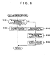
- the clutch actuator when the automatic clutch mode is selected by the selection means, the clutch actuator is controlled based on the operation state of the clutch operation member as described previously. Moreover, when the automatic clutch mode is selected by the selection means, the clutch actuator is controlled based on the parameter that is different from the operation state of the clutch operation member.
- the selection means may select the automatic clutch mode when a vehicle speed, which is a driving speed of the vehicle, is equal to or less than a specified value.
- the selection means selects the automatic clutch mode when the vehicle speed detected by vehicle speed detection means, or the like, is equal to or less than the specified value. Then, in accordance with the selected automatic clutch mode, the second clutch control means controls the clutch actuator. Therefore, when driving at a low speed in an urban area or on a congested road, the clutch is interrupted/resume without the operation of the clutch operation member. As a result, when driving at such low speeds, it is possible to free the driver from the bother of the clutch operation.
- a selection switch operated at the time of selecting either the manual clutch mode or the automatic clutch mode may be further provided. Accordingly, the selection means may select the mode instructed by an operation of the selection switch as the clutch mode for control of the clutch actuator.
- the selection means may switch to the automatic clutch mode if a problem occurs while the manual clutch mode is selected.
- the selection means forcibly switches to the automatic clutch mode if a problem occurs while the manual clutch mode is selected. Therefore, even in the event of a problem, by interrupting/resuming the clutch and shifting using the transmission, it is possible to conduct accident-avoidance driving
- the selection means may select the automatic clutch mode when the vehicle takes off.
- the selection means selects the automatic clutch mode using the second control means when take off of the vehicle is detected by take off detection means, or the like. Depending on this selection result, the second control means controls the clutch actuator based on the parameter which is different to the operation state of the clutch operation member. Therefore, when the vehicle takes off, it is possible to continued interruption/resumption the clutch without the operation of the clutch operation member by the driver.
- moving means may be further provided for moving, when the automatic clutch mode is selected by the selection means, the clutch operation member to a position which is different to that during the control by the manual clutch mode.
- operation load setting means may be further provided for setting the operation load with respect to the operation amount of the clutch operation member.
- the operation load with respect to the operation amount of the clutch operation member can be freely set by the operation load setting means.
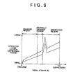
- the operation load setting means may set a degree of change of the operation load of the clutch operation member with respect to the operation amount such that it is different to a degree of change in a non-predetermined region.
- the operation load when the driver operates the clutch operation member, the operation load also changes in accordance with the change of the operation amount. For example, as the operation amount increases, the operation load increases.
- the degree of change of the operation load with respect to the operation amount becomes different to the degree of change in the non-predetermined region. In other words, in the process of operating the clutch operation member, when the operation amount reaches the predetermined region, the operation load changes (increases or decreases) in a manner different to before.
- the predetermined region is set so as to be at the boundary of a region where the clutch is in a disengaged state and a region where the clutch is in a partially engaged state
- an operation load changes in a manner which is different to that up until now.
- the driver is able to discern that the clutch is in the partially engaged state or a state just prior to entering the partially engaged state.
- shift control means and vehicle speed detection means may be further provided.
- the shift control means controls the transmission and vehicle speed detection means detect the vehicle speed, which is a driving speed of the vehicle.
- the shift control means may switch a shift speed of the transmission to neutral when the vehicle speed detection means detects a predetermined vehicle speed or lower speed (including a state where the vehicle is stopped), during control of the clutch actuator based on the operation state of the clutch operation member.
- the shift control means when the vehicle speed detection means detects the predetermined vehicle speed or lower speed (including the stopped state), the shift control means forcibly switches the shift speed of the transmission to neutral, during control of the clutch actuator based on the operation state of the clutch operation member. Therefore, when the vehicle speed is the predetermined vehicle speed or lower speed (including the stopped state), it is possible to maintain the vehicle in this speed state without the operation of the clutch operation member by the driver to disconnect the clutch. As a result, it is possible to reduce driver fatigue arising from continuation of the operation of the clutch operation member.
- FIGS. 1 to 5 A first embodiment of the invention will be described below referring to FIGS. 1 to 5.
- a vehicle 10 is equipped with an engine 11 as a power source.
- a crankshaft 12 serving as an output shaft of the engine 11 has a flywheel 13 attached so as to be integrally rotatable.
- a transmission 15 is connected via a clutch 14 to the flywheel 13. The clutch 14 transmits rotation of the crankshaft 12 to the transmission 15 and shuts off this rotation transmission.
- a release bearing 22 is mounted on the input shaft 17 so as to be capable of sliding in the axial direction. Moreover, in the vicinity of the release bearing 22, a release fork 23 is rotatably supported by a shaft 24, and one end (a lower end in FIG. 2) thereof abuts with the release bearing 22.
- a release cylinder 25 is connected via a rod 27 and a piston 26 to the other end (an upper end in FIG. 2) of the release fork 23.
- An oil pump, not shown, is connected via a linear solenoid valve, not shown, to the release cylinder 25.
- the release cylinder 25, the linear solenoid valve, the oil pump, and so on, compose a clutch actuator 28.
- hydraulic fluid is supplied to the release cylinder 25 by the oil pump.
- a hydraulic fluid pressure acting on the piston 26 of the release cylinder 25 is regulated by regulation of an opening degree of the linear solenoid valve.
- the movement amount of the piston 26 can be expressed as a stroke (0 to 100 %) of the clutch actuator 28 (refer to the vertical axes of FIGS. 3 and 4).
- this stroke is divided into three regions: an engaged region, a partially engaged region and a disengaged region.
- the friction force is 'large' and the clutch 14 is connected (engaged), the pressure plate 19, the clutch disk 18 and the flywheel 13 rotate integrally, and power transmission from the engine 11 to the transmission 15 is conducted.
- the clutch torque reaches the maximum value.
- the friction force is 'medium' and the clutch 14 enters a partially engaged state, where the pressure plate 19, the clutch disk 18 and the flywheel 13 are connected while sliding. At this time, the value of the clutch torque is smaller than that in the engaged region.
- the friction force is 'small' and the clutch 14 is disconnected, rotation of the flywheel 13 is not transmitted to the clutch disk 18, and power transmission from the engine 11 to the transmission 15 is shut off. At this time, the value of the clutch torque is smaller than that in the partially engaged region.
- absolute values may be used for the stroke of the clutch actuator, by defining a certain point as a reference point, displacement from this reference point may be used for relative values.
- Reference points which may be adopted are, for example, a point where the clutch disk 18 completely connects with the flywheel 13 (a clamp point), a point where the clutch disk 18 contacts the flywheel 13 (a touch point), a point where the clutch torque reaches a definite value, and a point, determined by design specifications, at which a clutch disk is maximally distant from the clamp point.
- the transmission 15 shown in FIG. 1 has the same construction as a commonly known manual transmission such as a parallel gear type transmission having five forward speeds and one reverse speed.
- the transmission 15 is provided with the input shaft 17 and an output shaft (not shown in the drawing).
- the input shaft 17 is connected to the clutch disk 18 as described before.
- the output shaft is connected to a driving wheel via a drive shaft, a differential gear, an axle, and so on, and rotation of the output shaft is transmitted to the driving wheel through these members.
- the transmission 15 is provided with a plurality of paired shift gear trains (shift speeds) and a plurality of sleeves, in addition to the input shaft 17 and the output shaft. Moreover, the transmission 15 is also provided with a transmission actuator 29 for switching shift speeds of the transmission 15.
- This transmission actuator 29 is composed by cylinders (a shift cylinder, a select cylinder), like the release cylinder 25, a valve, an oil pump, and so on. For this oil pump, it is possible to share the oil pump supplying oil to the release cylinder 25 described above.
- the sleeves are moved in the axial direction of the output shaft in the transmission 15. As a result of this movement, the gears are meshed with each other, and power transmission in a specific shift gear train is enabled.
- power transmission in each respective gear train is shut off.
- a clutch operation member operated by a driver when interrupting/resuming the clutch 14 is disposed in the vicinity of a driver's seat.
- a clutch pedal 31depressed by the driver and rotatably supported by a shaft 30 is used for the clutch operation member.
- the clutch pedal 31, unlike conventional ones, is not mechanically connected to the release cylinder 25.
- a depression amount of the clutch pedal 31 can be expressed by a stroke (hereinafter referred to as 'a pedal stroke'). As shown by the horizontal axes of FIGS. 3 and 4, the pedal stroke takes a value of 0 to 100 %.
- the pedal stroke is 0 % when the clutch pedal 31 is not depressed, and 100 % when depressed as far as is possible.
- an operation load regulation device 32 for regulating an operation load (a clutch depression force) thereof is disposed in the vicinity of the clutch pedal 31.
- the operation load regulation device 32 includes, for example, an electric motor, a spring, or the like.
- a spring it is important to select one having an appropriate spring force.
- an actuator such as an electric motor, or the like
- unlike the case of using the spring it is possible to discretionarily change an operation load in accordance with a depression amount of the clutch pedal 31, a state of the vehicle 10, and so on.
- a device using a pressure of a fluid such as an oil pressure, an air pressure, or the like, may be used.
- a stroke sensor 41 is disposed in the vicinity of the clutch pedal 31 as means for detecting an operation state thereof.
- the operation state in this case is an operation amount of the clutch pedal 31, that is, the depression amount (the pedal stroke).
- a shift position sensor 42 for detecting a position of the shift lever 37 is disposed in the shift device 36.
- two stroke sensors 43 and 44 for detecting a shift direction and a selection direction of the gear, respectively, are disposed.
- a vehicle speed sensor 45 serving as means for detecting a driving speed (a vehicle speed SPD) of the vehicle 10
- a revolution speed sensor 46 which detects a revolution speed of the engine 11, and so on, are also provided.
- these sensors are merely examples, and other sensor may be used.
- an electronic control unit (referred to hereinafter as 'ECU') 51 is disposed in the vehicle 10.
- the ECU 51 is used as means for controlling interruption/resumption of the clutch 14 through control of the clutch actuator 28.
- the ECU 51 is used as means for controlling shifting of the transmission 15 through control of the transmission actuator 29.
- the ECU 51 includes a microcomputer as a core, and executes various kinds of control based on the result of a calculation process conducted by a central processing unit (referred to hereinafter as 'CPU') in accordance with a control program, initial data, a control map, or the like, stored in a read-only-memory (referred to hereinafter as 'ROM') 52.
- the calculation result by the CPU is temporarily stored in a random-access-memory (referred to hereinafter as 'RAM').
- the ECU 51 controls the transmission actuator 29 based on a detection signal of the shift position sensor 42, and thereby operates the shift speed to a shift speed selected through operation of the shift lever 37.
- the transmission 15 is switched to the reverse shift speed.
- the transmission 15 is switched to a power transmission shut off state.
- the shift lever 37 is operated to the + position or the - position, which are defined with respect to the neutral position of the sequential position, the plurality of forward shift speeds of the transmission 15 are upshifted or downshifted, respectively.
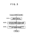
- FIG. 5 shows a clutch control routine for controlling an operation of the clutch actuator 28, which is one of various process executed by the ECU 51.
- FIGS. 3 and 4 Examples are shown in FIGS. 3 and 4.
- a degree of change (line inclination) of the desired stroke with respect to a change of the pedal stroke is different in respective regions. The degree of change is large in the engaged region and the disengaged region, and small in the partially engaged region. This means that a small change of the pedal stroke substantially changes the desired stroke in the engaged region and the disengaged region, whereas the desired stroke does not change significantly as long as the pedal stroke is not changed substantially in the partially engaged region.
- characteristics when the clutch pedal 31 is depressed (when the pedal stroke increases) and released (when the pedal stroke decreases), respectively, are slightly different from each other.
- the ECU 51 selects, from among the plurality of clutch characteristic maps stored in the ROM 52, the most appropriate one for a predetermined state amount pertinent to a condition of the vehicle 10.
- the predetermined state amount is, for example; the amount of a driving state of the vehicle 10 such as the vehicle speed SPD or an acceleration of the vehicle 10; the amount of a driving state of the engine 11 such as an engine revolution speed; or the amount of a state of the transmission 15 such as the shift speed.
- the predetermined state amount may be; the amount of a state of the clutch 14 such as a speed, an acceleration, a direction (a depression direction or a release direction); or the stroke of the piston 26 in the release cylinder 25 when operating the clutch pedal 31.
- a selection switch for selecting the clutch characteristic map may be provided in advance. The clutch characteristic map may then be selected in accordance with a state of this selection switch.
- the aforementioned state amounts may be used separately, or used in a combination of two or more.
- step S 120 the desired stroke of the clutch actuator 28 with respect to the pedal stroke at the time of detection by the stroke sensor 41 is determined while referring to the clutch characteristic map selected in the above manner.
- step S 130 the clutch actuator 28 is controlled in accordance with the desired stroke found in step S120.
- the clutch control routine is ended once.
- the clutch actuator 28 is controlled based on the pedal stroke detected by the stroke sensor 41.
- the clutch 14 is connected (engaged) or disconnected, and power from the engine 11 to the transmission 15 is transmitted or shut off.
- a clutch characteristic map may be used which defines a different relationship from those shown in FIGS. 3 and 4. Examples thereof are detailed below.
- the respective embodiments may be changed to a construction in which the shaft device 36 and the transmission 15 are mechanically connecting. This is to say, without the transmission actuator 29, shifting may be conducted by mechanically transmitting the operation of the shift lever 37 by the driver to the transmission 15.
- An operation member other than the clutch pedal 31 may be used as the clutch operation member.
- An ECU for controlling the clutch actuator 28 and an ECU for controlling the transmission actuator 29 may be separately provided.
- the condition of switching the shift speed of the transmission 15 to neutral during control of the clutch actuator 28 based on the operation state of the clutch operation member is that 'the vehicle is stopped' in the fifth embodiment.
- the condition may be that 'the vehicle speed SPD is equal to or less than a predetermined value.
- a vehicle clutch control device comprises a clutch actuator (28), a clutch pedal (31), a stroke sensor (41), and an electronic control unit (ECU) (51).
- the stroke sensor (41) detects a pedal stroke, which is a depression amount of the clutch pedal (31) by a driver.
- the ECU (51) controls the clutch actuator (28) based on the pedal stroke detected by the stroke sensor (41) without transmitting a movement of the clutch pedal (31) to the clutch actuator (28) via a transmission mechanism.
- the clutch actuator (28) is actuated, a clutch (14) interposed between an engine (11) and a transmission (15) is connected or disconnected, and power transmission from the engine (11) to the transmission (15) is interrupted or resumed.
Landscapes
- Engineering & Computer Science (AREA)
- Mechanical Engineering (AREA)
- General Engineering & Computer Science (AREA)
- Transportation (AREA)
- Chemical & Material Sciences (AREA)
- Combustion & Propulsion (AREA)
- Physics & Mathematics (AREA)
- Fluid Mechanics (AREA)
- Automation & Control Theory (AREA)
- Hydraulic Clutches, Magnetic Clutches, Fluid Clutches, And Fluid Joints (AREA)
- Control Of Driving Devices And Active Controlling Of Vehicle (AREA)
- Control Of Transmission Device (AREA)
Applications Claiming Priority (2)
| Application Number | Priority Date | Filing Date | Title |
|---|---|---|---|
| JP2002057495 | 2002-03-04 | ||
| JP2002057495A JP2003254356A (ja) | 2002-03-04 | 2002-03-04 | 車両用クラッチの制御装置 |
Publications (3)
| Publication Number | Publication Date |
|---|---|
| EP1342930A2 true EP1342930A2 (de) | 2003-09-10 |
| EP1342930A3 EP1342930A3 (de) | 2006-02-01 |
| EP1342930B1 EP1342930B1 (de) | 2008-10-01 |
Family
ID=27751039
Family Applications (1)
| Application Number | Title | Priority Date | Filing Date |
|---|---|---|---|
| EP03004664A Expired - Lifetime EP1342930B1 (de) | 2002-03-04 | 2003-03-03 | Fahrzeugkupplungssteuerungsgerät und -verfahren |
Country Status (3)
| Country | Link |
|---|---|
| EP (1) | EP1342930B1 (de) |
| JP (1) | JP2003254356A (de) |
| DE (1) | DE60323774D1 (de) |
Cited By (23)
| Publication number | Priority date | Publication date | Assignee | Title |
|---|---|---|---|---|
| EP1826440A1 (de) * | 2006-02-24 | 2007-08-29 | Yamaha Hatsudoki Kabushiki Kaisha | Kupplungssteuerungsvorrichtung |
| US7367923B2 (en) | 2004-12-10 | 2008-05-06 | Yamaha Hatsudoki Kabushiki Kaisha | Apparatus and method for controlling transmission of straddle-type vehicle |
| EP1777431A3 (de) * | 2005-10-19 | 2008-06-25 | Audi Ag | Kraftfahrzeug |
| EP1950447A1 (de) * | 2007-01-24 | 2008-07-30 | Delphi Technologies, Inc. | Betätigungssystem einer Kupplungsvorrichtung |
| WO2008138466A1 (de) * | 2007-05-11 | 2008-11-20 | Knorr-Bremse Systeme für Nutzfahrzeuge GmbH | Kupplungsstellvorrichtung für ein manuelles schaltgetriebe eines fahrzeugs und entsprechendes steuerungsverfahren |
| US7497804B2 (en) | 2006-04-18 | 2009-03-03 | Yamaha Hatsudoki Kabushiki Kaisha | Automatic gearshift control device and vehicle |
| CN100465469C (zh) * | 2006-04-18 | 2009-03-04 | 雅马哈发动机株式会社 | 离合器控制设备和车辆 |
| US7510503B2 (en) | 2006-02-24 | 2009-03-31 | Yamaha Hatsudoki Kabushiki Kaisha | Clutch failure detector, automatic clutch system and straddle-type vehicle |
| US7513849B2 (en) | 2006-04-18 | 2009-04-07 | Yamaha Hatsudoki Kabushiki Kaisha | Automated transmission controller and vehicle including the automated transmission controller |
| DE102006029044B4 (de) * | 2006-06-24 | 2009-12-10 | Ford Global Technologies, LLC, Dearborn | Verfahren zum Unterstützen des Anfahrens von Kraftfahrzeugen |
| US7635054B2 (en) | 2006-04-18 | 2009-12-22 | Yamaha Hatsudoki Kabushiki Kaisha Kabushiki Kaisha Moric | Clutch actuator, engine unit, and saddle type vehicle |
| US7654374B2 (en) | 2006-04-18 | 2010-02-02 | Yamaha Hatsudoki Kabushiki Kaisha | Automated transmission controller and vehicle including the automated transmission controller |
| US7665567B2 (en) | 2006-04-18 | 2010-02-23 | Yamaha Hatsudoki Kabushiki Kaisha | Shift actuator, vehicle, and method of integrating vehicle |
| US7673727B2 (en) | 2006-04-18 | 2010-03-09 | Yamaha Hatsudoki Kabushiki Kaisha | Automatic shift control device and vehicle |
| US7699151B2 (en) | 2006-04-18 | 2010-04-20 | Yamaha Hatsudoki Kabushiki Kaisha | Clutch actuator, engine unit, and saddle type vehicle |
| US7721858B2 (en) | 2006-04-18 | 2010-05-25 | Yamaha Hatsudoki Kabushiki Kaisha | Clutch actuator, engine unit, and saddle type vehicle |
| EP2192319A1 (de) * | 2008-12-01 | 2010-06-02 | GM Global Technology Operations, Inc. | Kupplungssystem |
| US7823472B2 (en) | 2004-07-01 | 2010-11-02 | Yamaha Hatsudoki Kabushiki Kaisha | Shift control device for vehicle, and vehicle including the shift control device |
| US7912613B2 (en) | 2004-07-01 | 2011-03-22 | Yamaha Hatsudoki Kabushiki Kaisha | Riding type vehicle |
| US20120265415A1 (en) * | 2011-04-18 | 2012-10-18 | GM Global Technology Operations LLC | Method for clutch control |
| US8403093B2 (en) | 2004-07-26 | 2013-03-26 | Yamaha Hatsudoki Kabushiki Kaisha | Speed change controller for saddle-ride type vehicles |
| DE102014000270A1 (de) * | 2013-01-15 | 2014-07-17 | Scania Cv Ab | Wahl der Betätigungsweise für eine Kupplung |
| WO2015123196A1 (en) * | 2014-02-14 | 2015-08-20 | Borgwarner Inc. | Hydraulic power pack actuator for controlling a manual clutch |
Families Citing this family (7)
| Publication number | Priority date | Publication date | Assignee | Title |
|---|---|---|---|---|
| JP2006214478A (ja) * | 2005-02-02 | 2006-08-17 | Hino Motors Ltd | クラッチ操作装置 |
| JP4953230B2 (ja) * | 2006-06-05 | 2012-06-13 | 日野自動車株式会社 | クラッチ制御装置およびその試験方法 |
| KR101519248B1 (ko) * | 2013-12-03 | 2015-05-11 | 현대자동차주식회사 | 수동변속기 차량의 변속 어시스트 방법 |
| JP2017198308A (ja) * | 2016-04-28 | 2017-11-02 | トヨタ自動車株式会社 | 車両用クラッチの制御装置 |
| JP6642460B2 (ja) * | 2017-01-16 | 2020-02-05 | トヨタ自動車株式会社 | 車両の制御装置 |
| JP7176542B2 (ja) * | 2020-01-29 | 2022-11-22 | いすゞ自動車株式会社 | 判定装置及び、判定方法 |
| CN121079516A (zh) * | 2023-03-29 | 2025-12-05 | 本田技研工业株式会社 | 离合器控制装置 |
Family Cites Families (4)
| Publication number | Priority date | Publication date | Assignee | Title |
|---|---|---|---|---|
| US4930081A (en) * | 1984-07-23 | 1990-05-29 | Eaton Corporation | Semi-automatic mechanical transmission control and control method |
| FR2712540A1 (fr) * | 1993-11-19 | 1995-05-24 | Lazareth Bernard | Dispositif d'assistance au débrayage dans les véhicules automobiles. |
| JP3198886B2 (ja) * | 1995-09-14 | 2001-08-13 | 三菱自動車工業株式会社 | 変速装置 |
| FR2812919B1 (fr) * | 2000-08-11 | 2006-10-20 | Valeo | Procede de commande d'un embrayage dans un vehicule automobile |
-
2002
- 2002-03-04 JP JP2002057495A patent/JP2003254356A/ja active Pending
-
2003
- 2003-03-03 DE DE60323774T patent/DE60323774D1/de not_active Expired - Lifetime
- 2003-03-03 EP EP03004664A patent/EP1342930B1/de not_active Expired - Lifetime
Cited By (35)
| Publication number | Priority date | Publication date | Assignee | Title |
|---|---|---|---|---|
| US8001864B2 (en) | 2004-07-01 | 2011-08-23 | Yamaha Hatsudoki Kabushiki Kaisha | Actuation force transmission mechanism and straddle-type vehicle |
| US7912613B2 (en) | 2004-07-01 | 2011-03-22 | Yamaha Hatsudoki Kabushiki Kaisha | Riding type vehicle |
| US7823472B2 (en) | 2004-07-01 | 2010-11-02 | Yamaha Hatsudoki Kabushiki Kaisha | Shift control device for vehicle, and vehicle including the shift control device |
| US8403093B2 (en) | 2004-07-26 | 2013-03-26 | Yamaha Hatsudoki Kabushiki Kaisha | Speed change controller for saddle-ride type vehicles |
| US7367923B2 (en) | 2004-12-10 | 2008-05-06 | Yamaha Hatsudoki Kabushiki Kaisha | Apparatus and method for controlling transmission of straddle-type vehicle |
| EP1777431A3 (de) * | 2005-10-19 | 2008-06-25 | Audi Ag | Kraftfahrzeug |
| EP2055978A1 (de) | 2006-02-24 | 2009-05-06 | Yamaha Hatsudoki Kabushiki Kaisha | Vorrichtung zur Kupplungssteuerung |
| US7510503B2 (en) | 2006-02-24 | 2009-03-31 | Yamaha Hatsudoki Kabushiki Kaisha | Clutch failure detector, automatic clutch system and straddle-type vehicle |
| EP1826440A1 (de) * | 2006-02-24 | 2007-08-29 | Yamaha Hatsudoki Kabushiki Kaisha | Kupplungssteuerungsvorrichtung |
| US7699151B2 (en) | 2006-04-18 | 2010-04-20 | Yamaha Hatsudoki Kabushiki Kaisha | Clutch actuator, engine unit, and saddle type vehicle |
| US7497804B2 (en) | 2006-04-18 | 2009-03-03 | Yamaha Hatsudoki Kabushiki Kaisha | Automatic gearshift control device and vehicle |
| US7635054B2 (en) | 2006-04-18 | 2009-12-22 | Yamaha Hatsudoki Kabushiki Kaisha Kabushiki Kaisha Moric | Clutch actuator, engine unit, and saddle type vehicle |
| US7654374B2 (en) | 2006-04-18 | 2010-02-02 | Yamaha Hatsudoki Kabushiki Kaisha | Automated transmission controller and vehicle including the automated transmission controller |
| US7665567B2 (en) | 2006-04-18 | 2010-02-23 | Yamaha Hatsudoki Kabushiki Kaisha | Shift actuator, vehicle, and method of integrating vehicle |
| US7673728B2 (en) | 2006-04-18 | 2010-03-09 | Yamaha Hatsudoki Kabushiki Kaisha | Automated transmission controller and vehicle including the automated transmission controller |
| US7673727B2 (en) | 2006-04-18 | 2010-03-09 | Yamaha Hatsudoki Kabushiki Kaisha | Automatic shift control device and vehicle |
| US7513849B2 (en) | 2006-04-18 | 2009-04-07 | Yamaha Hatsudoki Kabushiki Kaisha | Automated transmission controller and vehicle including the automated transmission controller |
| US7721858B2 (en) | 2006-04-18 | 2010-05-25 | Yamaha Hatsudoki Kabushiki Kaisha | Clutch actuator, engine unit, and saddle type vehicle |
| US7881847B2 (en) | 2006-04-18 | 2011-02-01 | Yamaha Hatsudoki Kabushiki Kaisha | Clutch control device and vehicle |
| CN100465469C (zh) * | 2006-04-18 | 2009-03-04 | 雅马哈发动机株式会社 | 离合器控制设备和车辆 |
| DE102006029044B4 (de) * | 2006-06-24 | 2009-12-10 | Ford Global Technologies, LLC, Dearborn | Verfahren zum Unterstützen des Anfahrens von Kraftfahrzeugen |
| EP1950447A1 (de) * | 2007-01-24 | 2008-07-30 | Delphi Technologies, Inc. | Betätigungssystem einer Kupplungsvorrichtung |
| US8302756B2 (en) | 2007-05-11 | 2012-11-06 | Knorr-Bremse Systeme Fuer Nutzfahrzeuge Gmbh | Clutch actuation device for a manual transmission of a vehicle and corresponding control method |
| WO2008138466A1 (de) * | 2007-05-11 | 2008-11-20 | Knorr-Bremse Systeme für Nutzfahrzeuge GmbH | Kupplungsstellvorrichtung für ein manuelles schaltgetriebe eines fahrzeugs und entsprechendes steuerungsverfahren |
| WO2010063337A1 (en) * | 2008-12-01 | 2010-06-10 | Gm Global Technology Operations, Inc. | Clutch system |
| EP2192319A1 (de) * | 2008-12-01 | 2010-06-02 | GM Global Technology Operations, Inc. | Kupplungssystem |
| US20120265415A1 (en) * | 2011-04-18 | 2012-10-18 | GM Global Technology Operations LLC | Method for clutch control |
| CN102748462A (zh) * | 2011-04-18 | 2012-10-24 | 通用汽车环球科技运作有限责任公司 | 用于离合器控制的方法 |
| US8798884B2 (en) * | 2011-04-18 | 2014-08-05 | Gm Global Technology Operations, Llc | Method for clutch control |
| CN102748462B (zh) * | 2011-04-18 | 2016-09-14 | 通用汽车环球科技运作有限责任公司 | 用于离合器控制的方法 |
| DE102014000270A1 (de) * | 2013-01-15 | 2014-07-17 | Scania Cv Ab | Wahl der Betätigungsweise für eine Kupplung |
| WO2015123196A1 (en) * | 2014-02-14 | 2015-08-20 | Borgwarner Inc. | Hydraulic power pack actuator for controlling a manual clutch |
| CN105980741A (zh) * | 2014-02-14 | 2016-09-28 | 博格华纳公司 | 用于控制手动离合器的液压动力机组致动器 |
| US10125828B2 (en) | 2014-02-14 | 2018-11-13 | Borgwarner Inc. | Hydraulic power pack actuator for controlling a manual clutch |
| CN105980741B (zh) * | 2014-02-14 | 2021-03-23 | 博格华纳公司 | 用于控制手动离合器的液压动力机组致动器 |
Also Published As
| Publication number | Publication date |
|---|---|
| DE60323774D1 (de) | 2008-11-13 |
| EP1342930B1 (de) | 2008-10-01 |
| JP2003254356A (ja) | 2003-09-10 |
| EP1342930A3 (de) | 2006-02-01 |
Similar Documents
| Publication | Publication Date | Title |
|---|---|---|
| EP1342930B1 (de) | Fahrzeugkupplungssteuerungsgerät und -verfahren | |
| JPH11141663A (ja) | 自動車のオートマティックトランスミッションを制御するための装置 | |
| US20070232443A1 (en) | Speed change control device for automatic transmission and control method thereof | |
| US7354378B2 (en) | Motor vehicle, control unit, driving force transmission system, and motor vehicle control method | |
| US4926994A (en) | Automatic clutch control apparatus | |
| EP0361943B1 (de) | Automatisches Getriebesystem für Fahrzeuge | |
| US4825993A (en) | Automatic transmission system for vehicles | |
| EP1167111B1 (de) | Vorrichtung zur Steuerung einer Kupplung | |
| US5024305A (en) | Method for controlling vehicle transmission systems | |
| JPH09324852A (ja) | 車両用変速機の変速制御装置 | |
| JP4432962B2 (ja) | 変速機の制御装置 | |
| JP2008256189A (ja) | 自動クラッチのトルク伝達開始点学習方法及びトルク伝達開始点学習装置 | |
| JP4042290B2 (ja) | 自動クラッチのクリープ制御装置 | |
| JP2006111196A (ja) | 車両の制御装置 | |
| JPH10318288A (ja) | 自動クラッチ制御装置 | |
| JP3580998B2 (ja) | 自動変速機の制御装置 | |
| JP3752959B2 (ja) | 機械式自動変速機の変速制御装置 | |
| JP4848743B2 (ja) | 自動変速機の制御装置 | |
| EP1462293B1 (de) | Fahrzeugsteuerung | |
| JP3619854B2 (ja) | 車両用自動変速機の変速制御方法 | |
| EP1288535B1 (de) | Atomatisiertes Fahrzeuggetriebe und sein Steuerverfahren | |
| KR100290356B1 (ko) | 자동변속기차량의브레이킹시변속제어방법 | |
| JPH11351374A (ja) | 自動変速機の変速制御装置 | |
| JPH112259A (ja) | 自動クラッチ制御装置 | |
| JPH10338060A (ja) | 自動クラッチ制御装置 |
Legal Events
| Date | Code | Title | Description |
|---|---|---|---|
| PUAI | Public reference made under article 153(3) epc to a published international application that has entered the european phase |
Free format text: ORIGINAL CODE: 0009012 |
|
| 17P | Request for examination filed |
Effective date: 20030311 |
|
| AK | Designated contracting states |
Kind code of ref document: A2 Designated state(s): AT BE BG CH CY CZ DE DK EE ES FI FR GB GR HU IE IT LI LU MC NL PT RO SE SI SK TR |
|
| AX | Request for extension of the european patent |
Extension state: AL LT LV MK |
|
| PUAL | Search report despatched |
Free format text: ORIGINAL CODE: 0009013 |
|
| AK | Designated contracting states |
Kind code of ref document: A3 Designated state(s): AT BE BG CH CY CZ DE DK EE ES FI FR GB GR HU IE IT LI LU MC NL PT RO SE SI SK TR |
|
| AX | Request for extension of the european patent |
Extension state: AL LT LV MK |
|
| AKX | Designation fees paid |
Designated state(s): CZ DE FR GB IT |
|
| 17Q | First examination report despatched |
Effective date: 20060413 |
|
| 17Q | First examination report despatched |
Effective date: 20060413 |
|
| GRAP | Despatch of communication of intention to grant a patent |
Free format text: ORIGINAL CODE: EPIDOSNIGR1 |
|
| GRAS | Grant fee paid |
Free format text: ORIGINAL CODE: EPIDOSNIGR3 |
|
| GRAA | (expected) grant |
Free format text: ORIGINAL CODE: 0009210 |
|
| AK | Designated contracting states |
Kind code of ref document: B1 Designated state(s): CZ DE FR GB IT |
|
| REG | Reference to a national code |
Ref country code: GB Ref legal event code: FG4D |
|
| REF | Corresponds to: |
Ref document number: 60323774 Country of ref document: DE Date of ref document: 20081113 Kind code of ref document: P |
|
| PLBE | No opposition filed within time limit |
Free format text: ORIGINAL CODE: 0009261 |
|
| STAA | Information on the status of an ep patent application or granted ep patent |
Free format text: STATUS: NO OPPOSITION FILED WITHIN TIME LIMIT |
|
| 26N | No opposition filed |
Effective date: 20090702 |
|
| PGFP | Annual fee paid to national office [announced via postgrant information from national office to epo] |
Ref country code: CZ Payment date: 20100215 Year of fee payment: 8 |
|
| PGFP | Annual fee paid to national office [announced via postgrant information from national office to epo] |
Ref country code: IT Payment date: 20110316 Year of fee payment: 9 Ref country code: FR Payment date: 20110317 Year of fee payment: 9 |
|
| PGFP | Annual fee paid to national office [announced via postgrant information from national office to epo] |
Ref country code: DE Payment date: 20110223 Year of fee payment: 9 Ref country code: GB Payment date: 20110302 Year of fee payment: 9 |
|
| PG25 | Lapsed in a contracting state [announced via postgrant information from national office to epo] |
Ref country code: CZ Free format text: LAPSE BECAUSE OF NON-PAYMENT OF DUE FEES Effective date: 20110303 |
|
| REG | Reference to a national code |
Ref country code: GB Ref legal event code: 746 Effective date: 20111114 |
|
| REG | Reference to a national code |
Ref country code: DE Ref legal event code: R084 Ref document number: 60323774 Country of ref document: DE Effective date: 20111109 |
|
| GBPC | Gb: european patent ceased through non-payment of renewal fee |
Effective date: 20120303 |
|
| REG | Reference to a national code |
Ref country code: FR Ref legal event code: ST Effective date: 20121130 |
|
| PG25 | Lapsed in a contracting state [announced via postgrant information from national office to epo] |
Ref country code: GB Free format text: LAPSE BECAUSE OF NON-PAYMENT OF DUE FEES Effective date: 20120303 Ref country code: FR Free format text: LAPSE BECAUSE OF NON-PAYMENT OF DUE FEES Effective date: 20120402 |
|
| REG | Reference to a national code |
Ref country code: DE Ref legal event code: R119 Ref document number: 60323774 Country of ref document: DE Effective date: 20121002 |
|
| PG25 | Lapsed in a contracting state [announced via postgrant information from national office to epo] |
Ref country code: IT Free format text: LAPSE BECAUSE OF NON-PAYMENT OF DUE FEES Effective date: 20120303 |
|
| PG25 | Lapsed in a contracting state [announced via postgrant information from national office to epo] |
Ref country code: DE Free format text: LAPSE BECAUSE OF NON-PAYMENT OF DUE FEES Effective date: 20121002 |