EP1342934A2 - Boîte de vitesses à engrenages avec division de puissance - Google Patents
Boîte de vitesses à engrenages avec division de puissance Download PDFInfo
- Publication number
- EP1342934A2 EP1342934A2 EP03013221A EP03013221A EP1342934A2 EP 1342934 A2 EP1342934 A2 EP 1342934A2 EP 03013221 A EP03013221 A EP 03013221A EP 03013221 A EP03013221 A EP 03013221A EP 1342934 A2 EP1342934 A2 EP 1342934A2
- Authority
- EP
- European Patent Office
- Prior art keywords
- gear
- countershaft
- transmission
- pair
- ziii
- Prior art date
- Legal status (The legal status is an assumption and is not a legal conclusion. Google has not performed a legal analysis and makes no representation as to the accuracy of the status listed.)
- Withdrawn
Links
- 230000005540 biological transmission Effects 0.000 title claims description 133
- 230000008878 coupling Effects 0.000 description 27
- 238000010168 coupling process Methods 0.000 description 27
- 238000005859 coupling reaction Methods 0.000 description 27
- 230000009365 direct transmission Effects 0.000 description 7
- 230000007935 neutral effect Effects 0.000 description 4
- 238000002485 combustion reaction Methods 0.000 description 2
- 230000000750 progressive effect Effects 0.000 description 2
- 238000005452 bending Methods 0.000 description 1
- 238000010276 construction Methods 0.000 description 1
- 238000012423 maintenance Methods 0.000 description 1
Images


Classifications
-
- F—MECHANICAL ENGINEERING; LIGHTING; HEATING; WEAPONS; BLASTING
- F16—ENGINEERING ELEMENTS AND UNITS; GENERAL MEASURES FOR PRODUCING AND MAINTAINING EFFECTIVE FUNCTIONING OF MACHINES OR INSTALLATIONS; THERMAL INSULATION IN GENERAL
- F16H—GEARING
- F16H3/00—Toothed gearings for conveying rotary motion with variable gear ratio or for reversing rotary motion
- F16H3/02—Toothed gearings for conveying rotary motion with variable gear ratio or for reversing rotary motion without gears having orbital motion
- F16H3/08—Toothed gearings for conveying rotary motion with variable gear ratio or for reversing rotary motion without gears having orbital motion exclusively or essentially with continuously meshing gears, that can be disengaged from their shafts
- F16H3/087—Toothed gearings for conveying rotary motion with variable gear ratio or for reversing rotary motion without gears having orbital motion exclusively or essentially with continuously meshing gears, that can be disengaged from their shafts characterised by the disposition of the gears
- F16H3/093—Toothed gearings for conveying rotary motion with variable gear ratio or for reversing rotary motion without gears having orbital motion exclusively or essentially with continuously meshing gears, that can be disengaged from their shafts characterised by the disposition of the gears with two or more countershafts
- F16H3/097—Toothed gearings for conveying rotary motion with variable gear ratio or for reversing rotary motion without gears having orbital motion exclusively or essentially with continuously meshing gears, that can be disengaged from their shafts characterised by the disposition of the gears with two or more countershafts the input and output shafts being aligned on the same axis
-
- F—MECHANICAL ENGINEERING; LIGHTING; HEATING; WEAPONS; BLASTING
- F16—ENGINEERING ELEMENTS AND UNITS; GENERAL MEASURES FOR PRODUCING AND MAINTAINING EFFECTIVE FUNCTIONING OF MACHINES OR INSTALLATIONS; THERMAL INSULATION IN GENERAL
- F16H—GEARING
- F16H3/00—Toothed gearings for conveying rotary motion with variable gear ratio or for reversing rotary motion
- F16H3/006—Toothed gearings for conveying rotary motion with variable gear ratio or for reversing rotary motion power being selectively transmitted by parallel flow paths, e.g. dual clutch transmissions
-
- F—MECHANICAL ENGINEERING; LIGHTING; HEATING; WEAPONS; BLASTING
- F16—ENGINEERING ELEMENTS AND UNITS; GENERAL MEASURES FOR PRODUCING AND MAINTAINING EFFECTIVE FUNCTIONING OF MACHINES OR INSTALLATIONS; THERMAL INSULATION IN GENERAL
- F16H—GEARING
- F16H3/00—Toothed gearings for conveying rotary motion with variable gear ratio or for reversing rotary motion
- F16H3/02—Toothed gearings for conveying rotary motion with variable gear ratio or for reversing rotary motion without gears having orbital motion
- F16H3/08—Toothed gearings for conveying rotary motion with variable gear ratio or for reversing rotary motion without gears having orbital motion exclusively or essentially with continuously meshing gears, that can be disengaged from their shafts
- F16H3/087—Toothed gearings for conveying rotary motion with variable gear ratio or for reversing rotary motion without gears having orbital motion exclusively or essentially with continuously meshing gears, that can be disengaged from their shafts characterised by the disposition of the gears
- F16H3/093—Toothed gearings for conveying rotary motion with variable gear ratio or for reversing rotary motion without gears having orbital motion exclusively or essentially with continuously meshing gears, that can be disengaged from their shafts characterised by the disposition of the gears with two or more countershafts
- F16H2003/0933—Toothed gearings for conveying rotary motion with variable gear ratio or for reversing rotary motion without gears having orbital motion exclusively or essentially with continuously meshing gears, that can be disengaged from their shafts characterised by the disposition of the gears with two or more countershafts with coaxial countershafts
-
- F—MECHANICAL ENGINEERING; LIGHTING; HEATING; WEAPONS; BLASTING
- F16—ENGINEERING ELEMENTS AND UNITS; GENERAL MEASURES FOR PRODUCING AND MAINTAINING EFFECTIVE FUNCTIONING OF MACHINES OR INSTALLATIONS; THERMAL INSULATION IN GENERAL
- F16H—GEARING
- F16H2200/00—Transmissions for multiple ratios
- F16H2200/003—Transmissions for multiple ratios characterised by the number of forward speeds
- F16H2200/0052—Transmissions for multiple ratios characterised by the number of forward speeds the gear ratios comprising six forward speeds
-
- F—MECHANICAL ENGINEERING; LIGHTING; HEATING; WEAPONS; BLASTING
- F16—ENGINEERING ELEMENTS AND UNITS; GENERAL MEASURES FOR PRODUCING AND MAINTAINING EFFECTIVE FUNCTIONING OF MACHINES OR INSTALLATIONS; THERMAL INSULATION IN GENERAL
- F16H—GEARING
- F16H61/00—Control functions within control units of change-speed- or reversing-gearings for conveying rotary motion ; Control of exclusively fluid gearing, friction gearing, gearings with endless flexible members or other particular types of gearing
- F16H61/68—Control functions within control units of change-speed- or reversing-gearings for conveying rotary motion ; Control of exclusively fluid gearing, friction gearing, gearings with endless flexible members or other particular types of gearing specially adapted for stepped gearings
- F16H61/684—Control functions within control units of change-speed- or reversing-gearings for conveying rotary motion ; Control of exclusively fluid gearing, friction gearing, gearings with endless flexible members or other particular types of gearing specially adapted for stepped gearings without interruption of drive
- F16H61/688—Control functions within control units of change-speed- or reversing-gearings for conveying rotary motion ; Control of exclusively fluid gearing, friction gearing, gearings with endless flexible members or other particular types of gearing specially adapted for stepped gearings without interruption of drive with two inputs, e.g. selection of one of two torque-flow paths by clutches
-
- Y—GENERAL TAGGING OF NEW TECHNOLOGICAL DEVELOPMENTS; GENERAL TAGGING OF CROSS-SECTIONAL TECHNOLOGIES SPANNING OVER SEVERAL SECTIONS OF THE IPC; TECHNICAL SUBJECTS COVERED BY FORMER USPC CROSS-REFERENCE ART COLLECTIONS [XRACs] AND DIGESTS
- Y10—TECHNICAL SUBJECTS COVERED BY FORMER USPC
- Y10T—TECHNICAL SUBJECTS COVERED BY FORMER US CLASSIFICATION
- Y10T74/00—Machine element or mechanism
- Y10T74/18—Mechanical movements
- Y10T74/18056—Rotary to or from reciprocating or oscillating
- Y10T74/18088—Rack and pinion type
- Y10T74/18104—Shiftable pinion
-
- Y—GENERAL TAGGING OF NEW TECHNOLOGICAL DEVELOPMENTS; GENERAL TAGGING OF CROSS-SECTIONAL TECHNOLOGIES SPANNING OVER SEVERAL SECTIONS OF THE IPC; TECHNICAL SUBJECTS COVERED BY FORMER USPC CROSS-REFERENCE ART COLLECTIONS [XRACs] AND DIGESTS
- Y10—TECHNICAL SUBJECTS COVERED BY FORMER USPC
- Y10T—TECHNICAL SUBJECTS COVERED BY FORMER US CLASSIFICATION
- Y10T74/00—Machine element or mechanism
- Y10T74/19—Gearing
- Y10T74/19219—Interchangeably locked
- Y10T74/19223—Disconnectable counter shaft
-
- Y—GENERAL TAGGING OF NEW TECHNOLOGICAL DEVELOPMENTS; GENERAL TAGGING OF CROSS-SECTIONAL TECHNOLOGIES SPANNING OVER SEVERAL SECTIONS OF THE IPC; TECHNICAL SUBJECTS COVERED BY FORMER USPC CROSS-REFERENCE ART COLLECTIONS [XRACs] AND DIGESTS
- Y10—TECHNICAL SUBJECTS COVERED BY FORMER USPC
- Y10T—TECHNICAL SUBJECTS COVERED BY FORMER US CLASSIFICATION
- Y10T74/00—Machine element or mechanism
- Y10T74/19—Gearing
- Y10T74/19219—Interchangeably locked
- Y10T74/19228—Multiple concentric clutch shafts
-
- Y—GENERAL TAGGING OF NEW TECHNOLOGICAL DEVELOPMENTS; GENERAL TAGGING OF CROSS-SECTIONAL TECHNOLOGIES SPANNING OVER SEVERAL SECTIONS OF THE IPC; TECHNICAL SUBJECTS COVERED BY FORMER USPC CROSS-REFERENCE ART COLLECTIONS [XRACs] AND DIGESTS
- Y10—TECHNICAL SUBJECTS COVERED BY FORMER USPC
- Y10T—TECHNICAL SUBJECTS COVERED BY FORMER US CLASSIFICATION
- Y10T74/00—Machine element or mechanism
- Y10T74/19—Gearing
- Y10T74/19219—Interchangeably locked
- Y10T74/19242—Combined gear and clutch
Definitions
- the invention relates according to the one-part claim 1, a change-speed gearbox with two in the power flow parallel to each other arranged sub-transmissions.
- gear changes can be performed under load, with an overlap control of the power shift clutches.
- This can cost-effective automatic transmission can be achieved with good efficiency.
- the straight gears are assigned to a partial transmission and the odd gears to the other sub-transmission, so that can be switched sequentially under load, but not skipped over individual gears easily can be, so-called double upshift or double downshift.
- the second sub-transmission includes the gear pairs of forward gears II and V and an additional gear pair whose translation is equal to the ratio of the third gear, whose gear pair belongs to the first sub-transmission.
- a gear coupling for the third gear and the direct clutch for the fourth gear is combined to form a removable coupling with a common sliding sleeve, which can be coupled with a loose wheel of the gear pair for the third gear or with the output shaft.
- a gear change transmission is shown in DE 31 31 156 A1 in Fig. 1, which has two power shift clutches.
- the one power shift clutch is non-rotatably connected to a gear of a constant, which meshes with a second gear which is rotatably connected to a parallel countershaft.
- the other power shift clutch is rotatably connected to a gear which meshes with a loose wheel, which is rotatably mounted on said countershaft.
- the invention has for its object to further develop a generic change-speed gearbox, in particular to reduce their construction costs, costs and weight and to increase the efficiency. It is achieved according to the invention by the features of the independent claims. Further embodiments emerge from the subclaims.
- an input shaft is connected to an output shaft through at least a first and a second partial transmission.
- the two partial transmissions are arranged parallel to each other in the power flow.
- each Partial transmission has a frictional power shift clutch and an intermediate shaft, wherein each of the intermediate shaft via the power shift clutch with the input shaft is operatively connected.
- the change-speed gearbox has at least one transmission constant per sub-transmission, each having a gear on one of the two intermediate shafts, of which at least one operatively connected to a first countershaft arranged parallel to the input shaft.
- the power-shift clutch of the first sub-transmission can be brought into operative connection with the input shaft via a second countershaft parallel to the input shaft via the first transmission constant.
- This second countershaft can be brought into operative connection with the output shaft by at least one gear pair associated with the first subtransmission.
- the first gear constant on the countershaft concentric and non-rotatably mounted fixed gear, which meshes with a concentric and rotatably mounted idler gear on the intermediate shaft of the first subgear, whereas the other gear constant has two fixed wheels.
- gear constant on a countershaft can be driven off by two power shift clutches on at least one gear constant on a countershaft. It can be achieved with a certain number of gear pairs particularly many load switching options and in particular at least the most important double high and double downshifts under load without additional gear pairs.
- a gear of Transmission constants on an intermediate shaft designed as idler gear and via at least one switching element with the second power shift clutch operatively connected or preferably directly connectable via a respective switching element, each with an intermediate shaft a transmission constant particularly simple, space-saving and be brought into operative connection with the first and the second power shift clutch with a high efficiency or low losses by tooth engagement.
- the first, the second or both power shift clutches can advantageously be used for starting.
- the resulting from the startup load can be distributed to both power shift clutches.
- An excessive temperature can be avoided despite cost-effective dimensioning, the wear is reduced and the maintenance intervals can be extended.
- the second power shift clutch used to start from the first gear and mobility security can be increased.
- the power shift clutches can also be designed differently for different starting operations and / or used individually or together for starting from a higher gear.
- the power-shift clutches are advantageously used individually or jointly for starting depending on at least one operating parameter, for example, depending on one load, friction, temperature and / or wear detected at the power shift clutches, etc.
- the power shift clutch of the first partial transmission via the first transmission constant with a parallel to the input shaft second countershaft in operative connection can be brought, which is engageable by at least one of the first partial transmission associated gear pair with the output shaft in operative connection.
- the switchable second countershaft an additional torque path can be created.
- the output shaft can be connected to the intermediate shaft of the first partial transmission by means of an engageable and disengageable shifting element to form a direct transmission gear, advantageously three torque paths can be created between the input shaft and the output shaft.
- the torque paths can be used alternately and in particular a double downshift from the direct transmission gear and a double upshift to the direct transmission gear under load without additional gear pair can be made possible.
- the direct transmission gear is the highest gear.
- good efficiency can be achieved. Losses due to dental interventions can be avoided.
- a particularly space-saving change-speed gearbox with few gear pairs and a high number of powershift options, especially with double high and double switchback under load, can be achieved so that the gear constants are different from each other and at least one gear constant on both countershafts with the output shaft can be brought into operative connection. If at least two transmission constants can be operatively connected to each countershaft, it is particularly advantageous if each gear pair is brought into operative connection with at least two transmission constants. Each pair of gears can be assigned at least two gears or with more than two transmission constants more than two gears.
- the transmission constants can be connected to two countershafts in various embodiments that appear appropriate to the person skilled in the art. However, this can be achieved in a particularly space-saving and cost-effective manner with two countershafts arranged concentrically with one another, which can be operatively connected to one another by a switching element.
- the switching element is advantageously arranged space-saving on the side of the second countershaft facing the power shift clutches.
- the solution according to the invention that at least one transmission constant can be brought into operative connection with both power shift clutches and the solution according to the invention, that at least one countershaft with two transmission constants can be brought into operative connection, contribute independently to increase the powershifting possibilities and efficiency, save gear pairs and in particular in addition to a sequential switching under load to enable double upshifts and double downshifts under load.
- the solutions are independent of each other, but they are particularly advantageous applied together in a change-speed gearbox.
- a first pair of gearbox associated gear pair and the second Partial transmission associated gear pair is assigned to the direct transmission gear next smaller gear, which in particular double downshifts and double upshifts on and off this gear and load can be made possible.
- a double downshift from the transmission gear next smaller gear is often needed for overtaking and is considered an important switching operation.
- the gear change from the first to the second gear often takes place under high load.
- a gear pair is advantageously assigned to the lowest and the second lowest gear.
- the switching elements for the second transmission gear can be preselected, so that can be switched from the first to the second gear after starting up from the first gear alone through an overlap control of the power shift clutches.
- the gear pair of the gear trains associated with the forward gears is arranged closest to a shaft bearing of the output shaft in a transmission housing. Bending of the waves and wear can be reduced.
- a gear for the highest gear is advantageously arranged on the countershaft, which has a larger diameter than the other countershaft.
- the large diameter can be advantageously used for translation.
- a small shaft spacing and a small structural volume can be achieved by axially displacing switching elements of the partial transmissions are arranged. A conditional by the switching elements, unnecessarily large shaft spacing can be avoided.
- three gear pairs for six different forward gears and a gear pair for at least one reverse gear are arranged in addition to the two transmission constants.
- a gear of the gear pair associated with the fourth and sixth gear is disposed on the second countershaft and a gear of the gear pair associated with the third and fourth gear and a gear of the gear pair associated with the first and second gear is disposed on the first countershaft.
- An advantageous variant further consists in that a gear of the third and sixth gear pair associated gear pair on the second countershaft and a gear of the second and fourth gear pair associated gear pair and a gear of the first and second gear pair associated gear pair is disposed on the first countershaft , It can be advantageously achieved a progressive gradation of the gear change transmission and / or a first gear with a high gear ratio, for example, for use in an internal combustion engine with a turbocharger, in an internal combustion engine with a low power and / or in a terrain vehicle, etc.
- An advantageous gradation of the gears in particular a large transmission difference between the second and the fourth gear and / or with a progressive characteristic can be achieved by at least one gear for a fourth gear and a gear for a first and a second gear on the first countershaft and on a second countershaft, at least one gear for a sixth and a gear for a third gear is arranged.
- This space-saving many powershift options and degrees of freedom for a certain gradation of gears can be achieved by the gears on the second countershaft for the third and sixth gear are each designed as idler gear and operatively connected via a common switching element with the second countershaft.
- both power shift clutches can be closed especially when II to VI gear. Losses, in particular due to drag torque, and wear, especially on a thrust bearing of a crankshaft and on a release bearing of the power shift clutches can be reduced and the life can be increased.
- FIG. 1 and FIG. 2 serve to explain the embodiments according to FIGS. 6 to 9 claimed in the patent claims, FIG.
- FIG. 6 shows a variant according to the invention according to FIG. 1 with staggered switching elements
- FIG. 7 shows a variant according to the invention according to FIG. 6 with a different assignment of gear pairs to gear trains
- Fig. 8 shows a variant of the invention according to FIG. 6 with a sixth direct transmission gear
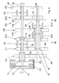
- Fig. 9 shows a variant of the invention according to FIG. 1 with four switchable gear pairs for six forward gears.
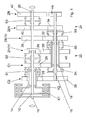
- Fig. 1 shows a change-speed gearbox in which an input shaft 10 is connected to an output shaft 20 through a first partial transmission 22 and a second partial transmission 24, which are arranged parallel to each other in the power flow.
- the partial gears 22, 24 each have a frictionally engaged power shift clutch K1, K2 and an intermediate shaft 12, 14.
- the intermediate shafts 12, 14 are concentric with each other and arranged coaxially to the input shaft 10 and can each operatively connected via the power shift clutch K1, K2 with the input shaft 10 become.
- the first intermediate shaft 12 of the first partial transmission 22 is on the one hand to the output shaft 20 by an engageable and disengageable gear clutch S2 to form a direct fifth gear V and on the other hand by the gear clutch S2 via a first gear constant C1 with a parallel to the output shaft 20, designed as a hollow shaft Countershaft 18 operatively connected.
- the countershaft 18 of the first sub-transmission 22 is formed by a gear pair ZIV / VI to form the highest and the second highest Gear IV, VI connected to the output shaft 20.
- the second countershaft 18 has a larger diameter than the first countershaft 16. The large diameter is advantageously used for the translation, in particular for the highest gear VI.
- the gear pair ZIV / VI has a non-rotatably connected to the output shaft 20 fixed gear 56 which meshes with a loose wheel 30.
- the idler gear 30 is arranged concentrically and rotatably on the countershaft 18 and can be coupled to the countershaft 18 by a gear clutch and disengageable S5.
- the intermediate shaft 12 is mounted, which in particular length can be saved.
- the gear pair ZIII / IV has a fixed gear 36, which is arranged concentrically and rotationally fixed on the output shaft 20 and a loose wheel 32, which is arranged concentrically and rotatably on a further output shaft 20 parallel to the countershaft 16.
- the idler gear 32 is coupled via the engageable and disengageable gear coupling S5 with the countershaft 18 and with a gear coupling S6 with the countershaft 16.
- the second formed as a hollow shaft intermediate shaft 14 of the second partial transmission 24 is connected via a second transmission constant C2 with the countershaft 16, which passes through the countershaft 18 of the first partial transmission 22 with play.
- the second transmission constant C2 has a concentric and rotatably mounted on the intermediate shaft 14 idler gear 28 which can be coupled via a gear coupling S1 with the intermediate shaft 14 is the concentric and non-rotatably connected to the countershaft fixed gear 38.
- the second part of the transmission 24 belonging countershaft 16 is via the gear pair ZIII / IV for the third and fourth gear III, IV, via a gear pair ZI / II for the first and the second gear I, II and a gear pair ZR for two reverse gears R connected to the output shaft 20.
- a reverse gear for example, for a winter operation and a reverse gear can be designed, for example, for a summer operation.
- the gear pair ZI / II for the first and the second gear I, II has a concentric and rotatably mounted on the output shaft 20 idler gear 40 which is coupled with a gear clutch S3 to the output shaft 20, and a concentric and rotationally fixed on the countershaft 16 arranged Fixed wheel 34.
- the gear pair ZR for the reverse gears R has a concentric and rotatably mounted on the output shaft 20 idler gear 42 which can be coupled by the engageable and disengageable gear coupling S3 to the output shaft 20, and a fixed wheel 44 which concentrically and rotatably connected to the countershaft 16 is. Between the idler gear 42 and the fixed gear 44 of the gear pair ZR a not-shown gear is arranged to reverse the rotation.
- the first transmission constant C1 has a concentric and non-rotatably mounted on the countershaft 16 fixed gear 46 which meshes with a concentrically and rotatably mounted idler gear 26 on the intermediate shaft 12 of the first sub-transmission.
- the idler gear 26 can be connected by the engageable and disengageable gear clutch S2 with the intermediate shaft 12 of the first sub-transmission 22 and by the gear coupling S1 with the intermediate shaft 14 of the second sub-transmission 24.
- the second power shift clutch K2 or the second intermediate shaft 14 is thereby operatively connected in addition to the second transmission constant C2 with the first transmission constant C1.
- the first transmission constant C1 can be brought into operative connection with the first, the second or both power shift clutches K1, K2 through the gear clutches S1 and S2.
- the intermediate shaft 14 of the second partial transmission 24 via the second transmission constant C2 by an engageable and disengageable gear coupling S4 with the fixed gear 46 of the transmission constant C1 and thus with the countershaft 18 of the first sub-transmission 22 and via the first sub-gear 22 associated gear pair ZIV / VI are operatively connected to the output shaft 20.
- the gear coupling S4 is arranged on the side of the second countershaft 18 facing the power shift clutches K1, K2.
- the intermediate shaft 12 can advantageously be operatively connected to the output shaft 20 via the gearbox clutch S4 which can be engaged and disengaged by means of the first gearbox C1 and the countershaft 16 and the gearwheel pairs ZI-II / IV, ZI / II, ZR associated with the second gearbox 24.
- each transmission constant C1 and C2 can be driven to the output shaft 20 via each gear pair ZI / II, ZIII / IV, ZIV / VI, ZR.
- the transmission constants C1 and C2 are different, so that each gear pair ZI / II, ZIII / IV, ZIV / VI, ZR is associated with two transmission gears.
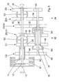
- FIG. 2 shows an overview of possible gear changes under load in each case from a source gear Q to a target gear Z.
- the possible gear changes are marked with X.
- Under GS, the geared clutches are listed. If two switching positions are possible in addition to a neutral position of the gear coupling, the coupled transmission constant or the coupled one is in each case connected to the gear coupling Called gear pair.
- the two transmission constants C1 and C2 and the three gear pairs ZI / II, ZIII / IV, ZIV / VI six different forward gears I, II, III, IV, V, VI can be achieved, wherein the first gear I 1,2, twice, the third gear III 1, 2 twice and the fourth gear IV 1, 2, 3 occurs three times.
- FIG. 2 shows an overview of possible gear changes under load in each case from a source gear Q to a target gear Z.
- the possible gear changes are marked with X.
- the geared clutches are listed. If, in addition to a neutral position of the gear coupling, two switching positions are possible, the coupled gear constant or the coupled gear pair is referred to the gear coupling in each case.
- the two transmission constants C1 and C2 and the three gear pairs ZI / II, ZIII / IV, ZIV / VI six different forward gears I, II, III, IV, V, VI can be achieved, wherein the first gear I 1,2, twice, the third gear III 1, 2 twice and the fourth gear IV 1, 2, 3 occurs three times.
- the gear clutch S2 couples the idler gear 26 of the first gear constant C1 with the intermediate shaft 12
- the gear clutch S4 couples the fixed gear 46 of the first gear constant C1 with the countershaft 16
- the gear clutch S3 couples the Losrad 40 of the gear pair ZI / II with the output shaft 20.
- the power flow extends from the input shaft 10 via the first power shift clutch K1, the intermediate shaft 12, the gear clutch S2, the transmission constant C1, the gear clutch S4, the countershaft 16, the gear pair ZI / II and the gear clutch S3 to the output shaft 20th
- the gear clutch S1 advantageously couples before starting from the first gear I 1 or in a neutral position of the gear change the idler gear 28 of the second gear constant C2 with the intermediate shaft 14, so that solely by an overlap control of the power shift clutch K1 on the power shift clutch K2 or can be switched by a simultaneous disengagement of the first and engaging the second power shift clutch K2 from the first to the second gear I 1 -II under load.
- the power flow from the input shaft 10 via the second power shift clutch K2, the intermediate shaft 14, the gear clutch S1, the transmission constant C2, the countershaft 16, the gear pair ZI / II and the gear clutch S3 to the output shaft 20.
- the gear couplings S2 and S4 can be disengaged in the second gear II without load.
- the idler gear 26 of the gear constant C1 is coupled through the gear clutch S2 with the intermediate shaft 12 and the idler gear 32 of the gear pair ZIII / IV through the gear coupling S5 with the countershaft 18.
- the power shift clutch K2 on the power shift clutch K1 is switched from the second to the third gear II-III 1 under load.
- the third gear III 1 of the power flow from the input shaft 10 via the first power shift clutch K1, the intermediate shaft 12, the gear clutch S2, the transmission constant C1, the countershaft 18, the gear clutch S5 and the gear pair ZIII / IV to the output shaft 20.
- the gear couplings S1 and S3 can be disengaged without load.
- the idler gear 28 of the transmission constant C2 is coupled by the gear coupling S1 with the intermediate shaft 14 and the idler gear 32 of the gear pair ZIII / IV with the countershaft 16.
- the power shift clutch K1 on the power shift clutch K2 is switched from the third to the fourth gear III 1 -IV 1 under load.
- the gear couplings S2 and S5 can be disengaged without load.
- the intermediate shaft 12 is coupled through the gear coupling S2 with the fixed gear 56 of the gear pair ZIV / VI and thus with the output shaft 20.
- the power-shift clutch K2 on the power-shift clutch K1 is switched from fourth to fifth gear IV 1 -V under load.
- the power flow in the fifth gear V extends from the input shaft 10 via the first power shift clutch K1, the intermediate shaft 12, the gear clutch S2 and the fixed gear 56 of the gear pair ZIV / VI to the output shaft 20.
- the gear clutches S1 and S6 can be disengaged without load.
- the power shift clutch K1 on the power shift clutch K2 is switched from the fifth to the sixth gear V-VI under load.
- the gear clutch S2 can be disengaged without load become.
- a reverse gear R the power shift clutch K2 is closed, the gear clutch S1 couples the idler gear 28 of the gear constant C2 to the intermediate shaft 14, and the gear clutch S3 couples the idler gear 42 of the gear pair ZR to the output shaft 20.
- the power flow is from the input shaft 10 via the power shift clutch K2, the intermediate shaft 14, the gear clutch S1, the gear constant C2, the countershaft 16, the gear pair ZR and via the gear clutch S3 to the output shaft 20.
- a second reverse gear with the gear constant C1 can be switched.
- the gear clutch S1 couples the intermediate shaft 14 and the gear clutch S2 couples the intermediate shaft 12 to the idler gear 26 of the gear constant C1.
- the gear clutch S4 couples the transmission constant C1 with the countershaft 16 and the gear clutch S3 couples the idler gear 40 of the gear pair ZI / II with the output shaft 20.
- the power flow runs from the input shaft 10 via the power shift clutches K1, K2, via the intermediate shafts 12, 14, via the gear clutches S1 S2, the gear constant C1, the gear clutch S4, the countershaft 16, the gear pair ZI / II and the gear clutch S3 to the output shaft 20. If the differential speed in the power shift clutches K1, K2 to zero, the power shift clutch K2 is opened.
- the idler gear 26 of the transmission constant C1 is coupled by the gear coupling S2 with the intermediate shaft 12 and the idler gear 30 of the gear pair ZIV / VI through the gear coupling S5 with the countershaft 18.
- the gear couplings S1 and S3 can be disengaged without load. Accordingly, can be switched back from the fourth gear IV 2 in the second gear II under load.
- the upshift from the second to the fourth gear II-IV 2 can optionally be connected via two different fourth gears IV 1.3 , in each of which the second power shift clutch K2 is closed, in the fifth gear V under load.
- the power shift clutch K2 is closed in the remaining fourth gear IV 3 .
- the gear clutch S1 couples the idler gear 26 of the gear constant C1 with the intermediate shaft 14 and the gear clutch S5 couples the idler gear 30 of the gear pair ZIV / VI with the countershaft 18.
- the power flow extends from the input shaft 10 via the second power shift clutch K2, the intermediate shaft 14, the Gear clutch S1, the transmission constant C1, the countershaft 18, the gear clutch S5 and the gear pair ZIV / VI to the output shaft 20th
- From the gear IV 1 and IV 3 can be switched in each case under load on the fourth gear IV 2 and vice versa.
- the gear 1 can IV under load via IV 2 to 3
- IV and IV 3 can under load via IV 2 to IV 1 are switched.
- the fourth gear IV 1, 2, 3 is always selected, from which a shift in the target gear under load is possible.
- speed change II and I 2 can be from 1 to IV I 1, from V to IV 3, from I to IV 1 and I 2, are switched from II to V and I 2 according to V.
- FIGS. 6 to 9 show the exemplary embodiments according to the invention. In the following, differences from the embodiments already described in FIGS. 1 and 2 will be described. With respect to the same components and functions, reference may be made to the description of the embodiments in FIGS. 1 and 2.
- the embodiment in Fig. 6 has two partial transmissions 82, 84 with staggered switching element S2, S3, S4, S5, and indeed the gear couplings S1 and S6 were saved compared to the embodiment in Fig. 1, whereby the change-speed gearbox axially and radially is particularly small ,
- the transmission constant C2 has two fixed wheels 66, 68.
- the assignment of the gear pairs ZI / II, ZIII / IV, ZVI / VI to the transmission gears I-VI corresponds to that in FIG. 1.
- Fig. 7 shows a change-speed gearbox with two partial transmissions 78, 80 with staggered gear clutches S2, S3, S4, S5, S6.
- the gear coupling S1 has been saved.
- the transmission constant C2 has two fixed wheels 66, 68.
- the assignment of the gear pairs ZI / II, ZII / IV, ZIII / VI to the gear ratios I-VI corresponds to that in FIG. 4.
- a change-speed gearbox with two partial transmissions 86, 88 is shown, the gear clutches S2, S3, S4, S5, S6 are arranged according to the change-speed gearbox in Fig. 7.
- the assignment of the gear pairs ZI / II, ZIII / IV, ZV corresponds to that in Fig. 5.
- the highest gear VI is designed as a direct gear VI.
- the embodiment shown in FIG. 9 has a partial transmission 92 with a gear 94 arranged on the first countershaft 16 for the fourth gear IV and a gear 34 for the first and second gear I, II.
- the gear change transmission has a partial transmission 90 with a gear the second countershaft 18 arranged gear 96 for the sixth gear VI and a gear 98 for the third gear III.
- the partial transmission 90 has two gear pairs ZIII, ZVI for the third and the sixth gear III, VI, and the partial transmission 92 has a gear pair ZI / II, for the first and second gear I, II and a gear pair ZIV for the fourth gear IV.
- the gears 96, 98 on the second countershaft 18 for the third and the sixth gear III, VI are each designed as idler gear and are operatively connected via a common switching element S12 with the second countershaft 18.
- the gears 96, 98 each mesh with a fixed wheel 114, 116 disposed on the output shaft 20.
- a gear clutch S13 is arranged on the first countershaft 16, via which the first countershaft 16 with the second countershaft 18 and arranged on the first countershaft 16 idler gear 94 of the gear pair ZIV with the first countershaft 16 can be coupled is.
- the idler gear 94 meshes with a
- the gear clutches S1, S4, S5 and S6 are omitted or the gear clutches S4 and S6 (FIG. 1) are combined to form the space-saving gear clutch S13 compared to the gear change transmission in FIG.
- the transmission constant C2 two fixed gears 66, 68.
- the transmission constants C1, C2 are arranged with a small axial distance, whereby axial space is saved.
- the switching element S2, S3, S12, S13 are arranged axially offset, whereby radial space is saved. Three free gears can be used for multiple circuits.
Landscapes
- Engineering & Computer Science (AREA)
- General Engineering & Computer Science (AREA)
- Mechanical Engineering (AREA)
- Structure Of Transmissions (AREA)
Applications Claiming Priority (5)
| Application Number | Priority Date | Filing Date | Title |
|---|---|---|---|
| DE19860250A DE19860250C1 (de) | 1998-12-24 | 1998-12-24 | Zahnräderwechselgetriebe mit zwei im Kraftfluß parallel zueinander angeordneten Teilgetrieben |
| DE19860250 | 1998-12-24 | ||
| DE1999118732 DE19918732A1 (de) | 1999-04-24 | 1999-04-24 | Zahnräderwechselgetriebe mit zwei im Kraftfluß parallel zueinander angeordneten Teilgetrieben |
| DE19918732 | 1999-04-24 | ||
| EP99964641A EP1141580B1 (fr) | 1998-12-24 | 1999-12-21 | Boite a pignons interchangeables comportant deux engrenages partiels places parallelement l'un a l'autre dans la chaine cinematique |
Related Parent Applications (2)
| Application Number | Title | Priority Date | Filing Date |
|---|---|---|---|
| EP99964641A Division EP1141580B1 (fr) | 1998-12-24 | 1999-12-21 | Boite a pignons interchangeables comportant deux engrenages partiels places parallelement l'un a l'autre dans la chaine cinematique |
| EP99964641.7 Division | 1999-12-21 |
Publications (2)
| Publication Number | Publication Date |
|---|---|
| EP1342934A2 true EP1342934A2 (fr) | 2003-09-10 |
| EP1342934A3 EP1342934A3 (fr) | 2006-07-26 |
Family
ID=26051059
Family Applications (3)
| Application Number | Title | Priority Date | Filing Date |
|---|---|---|---|
| EP03013222A Withdrawn EP1342935A3 (fr) | 1998-12-24 | 1999-12-21 | Boîte de vitesses à engrenages avec division de puissance |
| EP99964641A Expired - Lifetime EP1141580B1 (fr) | 1998-12-24 | 1999-12-21 | Boite a pignons interchangeables comportant deux engrenages partiels places parallelement l'un a l'autre dans la chaine cinematique |
| EP03013221A Withdrawn EP1342934A3 (fr) | 1998-12-24 | 1999-12-21 | Boîte de vitesses à engrenages avec division de puissance |
Family Applications Before (2)
| Application Number | Title | Priority Date | Filing Date |
|---|---|---|---|
| EP03013222A Withdrawn EP1342935A3 (fr) | 1998-12-24 | 1999-12-21 | Boîte de vitesses à engrenages avec division de puissance |
| EP99964641A Expired - Lifetime EP1141580B1 (fr) | 1998-12-24 | 1999-12-21 | Boite a pignons interchangeables comportant deux engrenages partiels places parallelement l'un a l'autre dans la chaine cinematique |
Country Status (4)
| Country | Link |
|---|---|
| US (1) | US6595077B1 (fr) |
| EP (3) | EP1342935A3 (fr) |
| DE (1) | DE59906610D1 (fr) |
| WO (1) | WO2000039484A1 (fr) |
Cited By (3)
| Publication number | Priority date | Publication date | Assignee | Title |
|---|---|---|---|---|
| US7231843B2 (en) | 2004-05-06 | 2007-06-19 | Zf Friedrichshafen Ag | Double clutch transmission |
| DE102004022414B4 (de) * | 2004-05-06 | 2010-04-15 | Zf Friedrichshafen Ag | Doppelkupplungsgetriebe |
| DE102007037568B4 (de) * | 2007-08-09 | 2016-09-29 | Daimler Ag | Doppelkupplungsgetriebe |
Families Citing this family (24)
| Publication number | Priority date | Publication date | Assignee | Title |
|---|---|---|---|---|
| US6869382B2 (en) * | 2003-05-07 | 2005-03-22 | Daimlerchrysler Corporation | Double-downshift gear strategy for a dual clutch automatic transmission |
| DE10325647A1 (de) | 2003-06-06 | 2004-02-05 | Daimlerchrysler Ag | Doppelkupplungsgetriebe |
| DE10335262A1 (de) | 2003-08-01 | 2005-03-03 | Daimlerchrysler Ag | Doppelkupplungsgetriebe mit koaxialem Antrieb und Abtrieb |
| DE10339758A1 (de) * | 2003-08-27 | 2005-06-09 | Daimlerchrysler Ag | Doppelkupplungsgetriebe in Windungsanordnung |
| DE10357292B4 (de) * | 2003-12-05 | 2006-02-02 | Voith Turbo Gmbh & Co. Kg | Verfahren für die Steuerung eines Antriebsstrangs für eine Strömungskraftmaschine mit Drehzahlführung, Kraftstoßreduktion und Kurzzeitenergiespeicherung |
| DE10361333A1 (de) * | 2003-12-18 | 2005-07-14 | Getrag Innovations Gmbh | Automatisches Wechselgetriebe |
| US7082850B2 (en) * | 2003-12-30 | 2006-08-01 | Eaton Corporation | Hybrid powertrain system |
| DE102004006732A1 (de) * | 2004-02-11 | 2005-09-01 | Daimlerchrysler Ag | Gestuftes leistungsverzweigtes Automatikgetriebe mit einer Doppelkupplung |
| US7210367B2 (en) * | 2004-02-20 | 2007-05-01 | Mazda Motor Corporation | Twin-clutch transmission |
| US6958028B2 (en) * | 2004-03-18 | 2005-10-25 | Ford Global Technologies, Llc | Ranged dual clutch transmission for motor vehicles |
| DE102004043387B4 (de) * | 2004-09-08 | 2015-05-28 | Zf Friedrichshafen Ag | Mehrganggetriebe in Vorgelegebauweise |
| DE102005044068A1 (de) | 2005-09-15 | 2007-03-29 | Daimlerchrysler Ag | Lastschaltbares Gruppengetriebe |
| DE102006015661A1 (de) | 2006-04-04 | 2007-10-11 | Daimlerchrysler Ag | Lastschaltbares Getriebe für ein Nutzfahrzeug |
| WO2007142637A1 (fr) * | 2006-06-07 | 2007-12-13 | O'connor, Brian, M. | Boîte à engrenages binaire |
| US7469609B2 (en) * | 2006-06-28 | 2008-12-30 | Ford Global Technologies, Llc | Output reduction dual clutch transmission with clutch coupler |
| EP2109724B1 (fr) * | 2007-01-16 | 2013-02-27 | BorgWarner, Inc. | Transmission à double embrayage |
| DE102007029634A1 (de) * | 2007-06-26 | 2009-01-08 | Daimler Ag | Zahnräderwechselgetriebe |
| DE102007040449A1 (de) | 2007-08-28 | 2009-03-05 | Daimler Ag | Zahnräderwechselgetriebe |
| US7779714B2 (en) * | 2007-11-02 | 2010-08-24 | Ford Global Technologies, Llc | Surrogate engine speed signal for controlling a dual clutch powershift transmission |
| DE102010041410A1 (de) * | 2010-09-27 | 2012-03-29 | Zf Friedrichshafen Ag | Doppelkupplungsgetriebe |
| DE102011011171A1 (de) * | 2011-02-14 | 2012-08-16 | Audi Ag | Antriebsanordnung für ein Kraftfahrzeug |
| US9097312B2 (en) * | 2011-08-30 | 2015-08-04 | Volvo Lastvagnar Ab | Multi-clutch transmission for a motor vehicle |
| US9145956B2 (en) | 2013-01-25 | 2015-09-29 | Gustomsc Resources B.V. | Torque sharing drive and torque sharing process |
| US9531237B2 (en) | 2013-12-19 | 2016-12-27 | Gustomsc Resources B.V. | Dual rack output pinion drive |
Citations (2)
| Publication number | Priority date | Publication date | Assignee | Title |
|---|---|---|---|---|
| DE3131156A1 (de) | 1981-08-06 | 1983-02-24 | Zahnradfabrik Friedrichshafen Ag, 7990 Friedrichshafen | "stirnradwechselgetriebe" |
| US4658663A (en) | 1984-03-30 | 1987-04-21 | Nissan Motor Co., Ltd. | Synchromesh transmission suited for use as automotive automatic transmission |
Family Cites Families (19)
| Publication number | Priority date | Publication date | Assignee | Title |
|---|---|---|---|---|
| CH339503A (de) * | 1955-11-28 | 1959-06-30 | Heim Georg | Zahnräderwechselgetriebe, insbesondere für Kraftfahrzeuge mit Verbrennungsmotoren |
| FR1469727A (fr) * | 1966-02-21 | 1967-02-17 | Bosch Gmbh Robert | Boîte de vitesses à carter stationnaire |
| GB1338606A (en) | 1970-06-05 | 1973-11-28 | Brown Gear Ind | Gearing |
| GB2095774A (en) | 1981-03-27 | 1982-10-06 | Automotive Prod Co Ltd | A change-speed rotary transmission |
| DE3131139C2 (de) | 1981-08-06 | 1985-09-12 | Zahnradfabrik Friedrichshafen Ag, 7990 Friedrichshafen | Stirnradwechselgetriebe |
| JPS58118355A (ja) * | 1982-01-08 | 1983-07-14 | Nissan Motor Co Ltd | 車両用変速機 |
| JPS59140941A (ja) * | 1983-01-28 | 1984-08-13 | Hino Motors Ltd | 自動トランスミツシヨン |
| SU1164088A1 (ru) * | 1984-03-29 | 1985-06-30 | Lifshits Isaak | Шестиступенчата соосна коробка передач |
| DE3546454C2 (de) | 1985-08-22 | 1994-11-03 | Porsche Ag | Gangschaltgetriebe für ein Kraftfahrzeug mit Doppelkupplung |
| EP0321873B1 (fr) * | 1987-12-19 | 1994-08-03 | GETRAG Getriebe- und Zahnradfabrik Hermann Hagenmeyer GmbH & Cie | Transmission à embrayage double et méthode pour son ajustage |
| DE3812327A1 (de) | 1987-12-19 | 1989-06-29 | Getrag Getriebe Zahnrad | Verfahren zum einstellen eines doppelkupplungsgetriebes und doppelkupplungsgetriebe |
| JPH0674824B2 (ja) * | 1988-11-28 | 1994-09-21 | 日野自動車工業株式会社 | ツインクラッチ式変速機 |
| DE4017961A1 (de) * | 1989-06-10 | 1990-12-13 | Zahnradfabrik Friedrichshafen | Steuersystem fuer ein lastschaltbares doppel-kupplungsgetriebe |
| DE3926570C2 (de) | 1989-08-11 | 1994-11-24 | Daimler Benz Ag | Gangwechselgetriebe mit zwei Vorgelegegetrieben für Kraftfahrzeuge |
| DE4031571A1 (de) * | 1990-10-05 | 1992-04-09 | Daimler Benz Ag | Verfahren zum schalten eines mehrwege-zahnraederwechselgetriebes mit jeweils durch eine zahnradkupplung mit ihrer welle kuppelbaren losraedern |
| KR100289507B1 (ko) | 1991-12-03 | 2001-06-01 | 가나이 쓰도무 | 자동차의 자동변속제어장치 및 제어방법 |
| DE4330170C2 (de) | 1993-09-07 | 2001-03-15 | Getrag Getriebe Zahnrad | Sechsgang-Doppelkupplungsgetriebe |
| KR970066191A (ko) | 1996-03-01 | 1997-10-13 | 가나이 쯔도무 | 자동 변속기의 제어 장치 및 제어 방법 |
| EP1013966B1 (fr) * | 1998-12-24 | 2002-09-25 | DaimlerChrysler AG | Boite de vitesses à engrenages avec division de puissance |
-
1999
- 1999-12-21 EP EP03013222A patent/EP1342935A3/fr not_active Withdrawn
- 1999-12-21 US US09/869,095 patent/US6595077B1/en not_active Expired - Lifetime
- 1999-12-21 EP EP99964641A patent/EP1141580B1/fr not_active Expired - Lifetime
- 1999-12-21 DE DE59906610T patent/DE59906610D1/de not_active Expired - Lifetime
- 1999-12-21 EP EP03013221A patent/EP1342934A3/fr not_active Withdrawn
- 1999-12-21 WO PCT/EP1999/010240 patent/WO2000039484A1/fr not_active Ceased
Patent Citations (2)
| Publication number | Priority date | Publication date | Assignee | Title |
|---|---|---|---|---|
| DE3131156A1 (de) | 1981-08-06 | 1983-02-24 | Zahnradfabrik Friedrichshafen Ag, 7990 Friedrichshafen | "stirnradwechselgetriebe" |
| US4658663A (en) | 1984-03-30 | 1987-04-21 | Nissan Motor Co., Ltd. | Synchromesh transmission suited for use as automotive automatic transmission |
Cited By (4)
| Publication number | Priority date | Publication date | Assignee | Title |
|---|---|---|---|---|
| US7231843B2 (en) | 2004-05-06 | 2007-06-19 | Zf Friedrichshafen Ag | Double clutch transmission |
| DE102004022414B4 (de) * | 2004-05-06 | 2010-04-15 | Zf Friedrichshafen Ag | Doppelkupplungsgetriebe |
| DE102004022413B4 (de) * | 2004-05-06 | 2010-04-15 | Zf Friedrichshafen Ag | Doppelkupplungsgetriebe |
| DE102007037568B4 (de) * | 2007-08-09 | 2016-09-29 | Daimler Ag | Doppelkupplungsgetriebe |
Also Published As
| Publication number | Publication date |
|---|---|
| EP1141580B1 (fr) | 2003-08-13 |
| EP1141580A1 (fr) | 2001-10-10 |
| EP1342934A3 (fr) | 2006-07-26 |
| US6595077B1 (en) | 2003-07-22 |
| DE59906610D1 (de) | 2003-09-18 |
| EP1342935A3 (fr) | 2006-07-26 |
| EP1342935A2 (fr) | 2003-09-10 |
| WO2000039484A1 (fr) | 2000-07-06 |
Similar Documents
| Publication | Publication Date | Title |
|---|---|---|
| EP1141580B1 (fr) | Boite a pignons interchangeables comportant deux engrenages partiels places parallelement l'un a l'autre dans la chaine cinematique | |
| EP1367294B1 (fr) | Boíte de vitesses à engrenages avec division de puissance | |
| EP1013966B1 (fr) | Boite de vitesses à engrenages avec division de puissance | |
| DE19860251C1 (de) | Zahnräderwechselgetriebe mit zwei Teilgetrieben mit je einer Lastschaltkupplung | |
| DE102007058425B4 (de) | Mehrgang-Doppelkupplungsgetriebe | |
| DE4405048C2 (de) | Automatisch schaltbares Stufenwechselgetriebe mit drei Planetensätzen | |
| DE102006009059B4 (de) | Doppelkupplungs-Getriebeanordnungen mit großem Übersetzungsbereich | |
| EP2195552B2 (fr) | Boîte de vitesses à engrenages comportant deux arbres d'entrée et deux embrayages | |
| DE102005016588B9 (de) | Mehrganggetriebe | |
| EP2558745B1 (fr) | Train d'engrenages à double embrayage et procédé pour actionner un train d'engrenages à double embrayage | |
| DE102010023824B4 (de) | Siebengang-Doppelkupplungsgetriebe mit vier Drehachsen | |
| EP2162635B1 (fr) | Boite de vitesses a engrenages | |
| WO2011157479A1 (fr) | Transmission à embrayage double | |
| DE19923185A1 (de) | Zahnräderwechselgetriebe mit zwei im Kraftfluß parallel zueinander angeordneten Teilgetrieben | |
| WO2003078864A1 (fr) | Boite de vitesses, notamment boite de vitesses a embrayage double | |
| DE10037398A1 (de) | Zahnräderwechselgetriebe | |
| EP3259493A1 (fr) | Boîte de vitesses à double embrayage pour véhicule à moteur | |
| DE938106C (de) | Kraftschluessiges Zahnraeder-Stufenschaltgetriebe mit Vorwaehlung | |
| DE19918734A1 (de) | Zahnräderwechselgetriebe mit zwei im Kraftfluß parallel zueinander angeordneten Teilgetrieben | |
| DE112011105576B4 (de) | Mehrkupplungsgetriebe für ein Kraftfahrzeug | |
| DE102011089167A1 (de) | Doppelkupplungsgetriebe in Vorgelegebauweise | |
| DE19850547B4 (de) | Mehrgängiges Mehrwege- Zahnräderwechselgetriebe | |
| EP0595059B1 (fr) | Boîte de vitesses pour véhicule automobile | |
| DE19850546C1 (de) | Mehrgängiges Mehrwege-Zahnräderwechselgetriebe | |
| DE19918732A1 (de) | Zahnräderwechselgetriebe mit zwei im Kraftfluß parallel zueinander angeordneten Teilgetrieben |
Legal Events
| Date | Code | Title | Description |
|---|---|---|---|
| PUAI | Public reference made under article 153(3) epc to a published international application that has entered the european phase |
Free format text: ORIGINAL CODE: 0009012 |
|
| 17P | Request for examination filed |
Effective date: 20030612 |
|
| AC | Divisional application: reference to earlier application |
Ref document number: 1141580 Country of ref document: EP Kind code of ref document: P |
|
| AK | Designated contracting states |
Kind code of ref document: A2 Designated state(s): DE |
|
| PUAL | Search report despatched |
Free format text: ORIGINAL CODE: 0009013 |
|
| AK | Designated contracting states |
Kind code of ref document: A3 Designated state(s): DE |
|
| AKX | Designation fees paid |
Designated state(s): DE |
|
| RAP1 | Party data changed (applicant data changed or rights of an application transferred) |
Owner name: DAIMLERCHRYSLER AG |
|
| STAA | Information on the status of an ep patent application or granted ep patent |
Free format text: STATUS: THE APPLICATION IS DEEMED TO BE WITHDRAWN |
|
| 18D | Application deemed to be withdrawn |
Effective date: 20070127 |