EP1342969A2 - Procédé et appareil de séchage de pièces - Google Patents
Procédé et appareil de séchage de pièces Download PDFInfo
- Publication number
- EP1342969A2 EP1342969A2 EP03010727A EP03010727A EP1342969A2 EP 1342969 A2 EP1342969 A2 EP 1342969A2 EP 03010727 A EP03010727 A EP 03010727A EP 03010727 A EP03010727 A EP 03010727A EP 1342969 A2 EP1342969 A2 EP 1342969A2
- Authority
- EP
- European Patent Office
- Prior art keywords
- workpieces
- liquid
- treatment container
- cleaning
- workpiece carrier
- Prior art date
- Legal status (The legal status is an assumption and is not a legal conclusion. Google has not performed a legal analysis and makes no representation as to the accuracy of the status listed.)
- Granted
Links
- 238000000034 method Methods 0.000 title claims abstract description 44
- 238000001035 drying Methods 0.000 title claims abstract description 23
- 239000007788 liquid Substances 0.000 claims abstract description 142
- 239000007921 spray Substances 0.000 claims abstract description 35
- 238000004140 cleaning Methods 0.000 abstract description 85
- 238000004519 manufacturing process Methods 0.000 abstract description 3
- 238000011068 loading method Methods 0.000 abstract description 2
- 238000006073 displacement reaction Methods 0.000 abstract 1
- 230000000694 effects Effects 0.000 description 11
- 238000001704 evaporation Methods 0.000 description 9
- 230000008020 evaporation Effects 0.000 description 8
- 230000005855 radiation Effects 0.000 description 8
- 238000010438 heat treatment Methods 0.000 description 7
- 239000002904 solvent Substances 0.000 description 4
- 239000013590 bulk material Substances 0.000 description 3
- 239000003921 oil Substances 0.000 description 3
- 230000002269 spontaneous effect Effects 0.000 description 3
- 239000000356 contaminant Substances 0.000 description 2
- 238000011109 contamination Methods 0.000 description 2
- 239000002360 explosive Substances 0.000 description 2
- 239000004519 grease Substances 0.000 description 2
- 230000007704 transition Effects 0.000 description 2
- 238000005406 washing Methods 0.000 description 2
- 230000000712 assembly Effects 0.000 description 1
- 238000000429 assembly Methods 0.000 description 1
- 238000005422 blasting Methods 0.000 description 1
- 238000009835 boiling Methods 0.000 description 1
- 239000011248 coating agent Substances 0.000 description 1
- 238000000576 coating method Methods 0.000 description 1
- 238000009833 condensation Methods 0.000 description 1
- 230000005494 condensation Effects 0.000 description 1
- 230000001419 dependent effect Effects 0.000 description 1
- 238000000227 grinding Methods 0.000 description 1
- 238000007654 immersion Methods 0.000 description 1
- 238000003780 insertion Methods 0.000 description 1
- 230000037431 insertion Effects 0.000 description 1
- 238000002156 mixing Methods 0.000 description 1
- 239000002245 particle Substances 0.000 description 1
- 230000000737 periodic effect Effects 0.000 description 1
- 238000005096 rolling process Methods 0.000 description 1
- 230000035945 sensitivity Effects 0.000 description 1
- 238000005507 spraying Methods 0.000 description 1
- 239000000126 substance Substances 0.000 description 1
- XLYOFNOQVPJJNP-UHFFFAOYSA-N water Substances O XLYOFNOQVPJJNP-UHFFFAOYSA-N 0.000 description 1
Images




Classifications
-
- F—MECHANICAL ENGINEERING; LIGHTING; HEATING; WEAPONS; BLASTING
- F26—DRYING
- F26B—DRYING SOLID MATERIALS OR OBJECTS BY REMOVING LIQUID THEREFROM
- F26B5/00—Drying solid materials or objects by processes not involving the application of heat
- F26B5/14—Drying solid materials or objects by processes not involving the application of heat by applying pressure, e.g. wringing; by brushing; by wiping
-
- B—PERFORMING OPERATIONS; TRANSPORTING
- B08—CLEANING
- B08B—CLEANING IN GENERAL; PREVENTION OF FOULING IN GENERAL
- B08B3/00—Cleaning by methods involving the use or presence of liquid or steam
- B08B3/04—Cleaning involving contact with liquid
- B08B3/045—Cleaning involving contact with liquid using perforated containers, e.g. baskets, or racks immersed and agitated in a liquid bath
-
- B—PERFORMING OPERATIONS; TRANSPORTING
- B08—CLEANING
- B08B—CLEANING IN GENERAL; PREVENTION OF FOULING IN GENERAL
- B08B3/00—Cleaning by methods involving the use or presence of liquid or steam
- B08B3/04—Cleaning involving contact with liquid
- B08B3/10—Cleaning involving contact with liquid with additional treatment of the liquid or of the object being cleaned, e.g. by heat, by electricity or by vibration
-
- F—MECHANICAL ENGINEERING; LIGHTING; HEATING; WEAPONS; BLASTING
- F26—DRYING
- F26B—DRYING SOLID MATERIALS OR OBJECTS BY REMOVING LIQUID THEREFROM
- F26B11/00—Machines or apparatus for drying solid materials or objects with movement which is non-progressive
- F26B11/18—Machines or apparatus for drying solid materials or objects with movement which is non-progressive on or in moving dishes, trays, pans, or other mainly-open receptacles
-
- F—MECHANICAL ENGINEERING; LIGHTING; HEATING; WEAPONS; BLASTING
- F26—DRYING
- F26B—DRYING SOLID MATERIALS OR OBJECTS BY REMOVING LIQUID THEREFROM
- F26B11/00—Machines or apparatus for drying solid materials or objects with movement which is non-progressive
- F26B11/18—Machines or apparatus for drying solid materials or objects with movement which is non-progressive on or in moving dishes, trays, pans, or other mainly-open receptacles
- F26B11/181—Machines or apparatus for drying solid materials or objects with movement which is non-progressive on or in moving dishes, trays, pans, or other mainly-open receptacles the receptacle being a foraminous, perforated or open-structured drum or drum-like container, e.g. rotating around a substantially horizontal or vertical axis; the receptacle being multiple perforated drums, e.g. in superimposed arrangement
-
- F—MECHANICAL ENGINEERING; LIGHTING; HEATING; WEAPONS; BLASTING
- F26—DRYING
- F26B—DRYING SOLID MATERIALS OR OBJECTS BY REMOVING LIQUID THEREFROM
- F26B5/00—Drying solid materials or objects by processes not involving the application of heat
- F26B5/04—Drying solid materials or objects by processes not involving the application of heat by evaporation or sublimation of moisture under reduced pressure, e.g. in a vacuum
-
- F—MECHANICAL ENGINEERING; LIGHTING; HEATING; WEAPONS; BLASTING
- F26—DRYING
- F26B—DRYING SOLID MATERIALS OR OBJECTS BY REMOVING LIQUID THEREFROM
- F26B5/00—Drying solid materials or objects by processes not involving the application of heat
- F26B5/04—Drying solid materials or objects by processes not involving the application of heat by evaporation or sublimation of moisture under reduced pressure, e.g. in a vacuum
- F26B5/048—Drying solid materials or objects by processes not involving the application of heat by evaporation or sublimation of moisture under reduced pressure, e.g. in a vacuum in combination with heat developed by electro-magnetic means, e.g. microwave energy
-
- F—MECHANICAL ENGINEERING; LIGHTING; HEATING; WEAPONS; BLASTING
- F26—DRYING
- F26B—DRYING SOLID MATERIALS OR OBJECTS BY REMOVING LIQUID THEREFROM
- F26B7/00—Drying solid materials or objects by processes using a combination of processes not covered by a single one of groups F26B3/00 and F26B5/00
Definitions
- the present invention relates to an apparatus and a method for drying workpieces.
- a device and a method for solvent-free cleaning of workpieces is known from DE 43 17 862 A1.
- Workpieces are placed in a wash tank, which is then sealed airtight and in which a vacuum is generated. Due to the negative pressure, liquid is sucked into the wash tank via a line connection, air being subsequently blown into the resulting liquid bath.
- DE 37 02 675 A1 describes a device for the wet cleaning of workpieces, in which a turbulence flow is generated in an immersion bath by means of a liquid jet, in which the workpieces are arranged for cleaning.
- the known devices and methods have the disadvantage that they are not very effective for cleaning workpieces with the smallest surface structures and in particular for cleaning very small workpieces that are introduced into the cleaning containers as bulk material.
- the aim of the present invention is therefore to provide a device for cleaning workpieces, with which a reliable cleaning of even the smallest workpieces and workpieces with filigree surface structures is possible, which works reliably on the basis of aqueous cleaning liquids without the addition of solvents and in which in particular the disadvantages mentioned above do not arise.
- the device has a treatment container in which a workpiece carrier for receiving the workpieces to be cleaned is arranged.
- a spray unit with outlet nozzles for dispensing cleaning liquid and / or a gaseous medium is arranged in the interior of the treatment container, which has a controllable liquid outlet and in which a negative pressure can be generated.
- the workpiece carrier and / or the spray unit are also rotatably arranged in the treatment container.
- the device according to the invention enables reliable cleaning of even the smallest workpieces when grease and oil residues are removed from the smallest recesses and openings.
- a liquid bath is generated in the treatment container, which at least partially surrounds the workpieces held by the workpiece carrier.
- cleaning liquid and possibly a gaseous medium are introduced into the liquid bath and the area above the liquid bath via the spray unit.
- the cleaning liquid emitted by the spray unit hits the workpieces, spontaneous evaporation occurs, with gas particles hitting the workpieces at high speed due to the energy released in the process and achieving a considerable cleaning effect.
- the cleaning liquid introduced under excess pressure and the possibly introduced gaseous medium cause turbulence and cavitation effects, which cause explosive blasting off of firmly adhering contaminants and of contamination in capillary inclusions of the workpieces.
- the workpieces are continuously fed to the different cleaning processes in the liquid bath and above the liquid bath and pass through the particularly cleaning-active interface area between the liquid bath and the vacuum area above it.
- the controllable liquid outlet is provided, via which a liquid quantity corresponding to the newly supplied liquid quantity runs out per time unit.
- the liquid drain preferably has a valve which is opened and closed periodically.
- the device according to the invention also has the advantage that, in addition to cleaning workpieces, it can also be used to dry the cleaned workpieces.
- a gaseous medium is introduced into the treatment container under excess pressure via the outlet nozzles of the spray unit, the gas jet striking the workpieces removing liquid residues adhering to the workpieces, which are suctioned off.
- the suction is preferably carried out by the vacuum pump or via a further suction device provided according to an embodiment of the invention, which is connected to a second suction opening of the treatment container.
- the further suction device is used, in particular, to quickly suck off the liquid vapors in the treatment container immediately after the cleaning process.
- a negative pressure generated by the vacuum pump in the treatment container accelerates the evaporation of the liquid residues removed from the workpieces by the gas jets.
- the workpieces are exposed to gas jets from constantly changing sides in order to effect the most complete possible drying.
- the workpiece carrier By rotating the workpiece carrier at the same time, particularly in the case of bulk material, the workpieces are constantly mixed so that all the workpieces are exposed to the gas jets in the course of the drying process.
- the treatment container advantageously has heating devices mounted on the outside for heating the treatment container during the drying process.
- heat radiators in the interior of the treatment container during the drying process emit heat radiation directed onto the workpieces, which, supported by the negative pressure existing in the treatment container, causes evaporation of liquid residues adhering to the workpieces.
- the heat radiators are advantageously arranged rotatably about the workpiece carrier in the treatment container.
- the present invention furthermore relates to a method for cleaning workpieces according to the independent patent claim 7, which can be carried out by means of the device according to the invention.
- a liquid bath is generated in a treatment container in which a workpiece carrier for receiving the workpieces is arranged, and a negative pressure is generated in the treatment container in an area above the liquid bath.
- the workpiece carrier or the workpieces are partially surrounded by the liquid bath.
- Cleaning liquid and / or a gaseous medium are then introduced into the treatment container under excess pressure via outlet nozzles of a spray unit, the liquid jets or the jets of the gaseous medium preferably being directed onto the workpieces.
- the workpiece carrier is moved in the treatment container in such a way that the workpieces alternately pass areas above and below a liquid level of the liquid bath so as to be exposed alternately to the different cleaning processes that take place above, below and in the border area between the liquid bath and the vacuum area to become.
- the workpiece carrier can be moved, for example, by periodic lifting and lowering or by rotation.
- the liquid level is preferably kept at least approximately constant during the cleaning process, to ensure that the workpieces alternately pass areas above and below the liquid level when the workpiece carrier moves.
- the liquid bath can be formed in the treatment tank by initially flooding the treatment tank to a predetermined liquid level, this liquid level being kept approximately constant when additional cleaning liquid flows in via a controllable liquid drain. Another possibility for generating the liquid bath is to keep the liquid drain closed at the beginning of the cleaning process until a corresponding amount of cleaning liquid has been introduced into the treatment container via the spray unit.
- Liquid vapors that form in the negative pressure area above the liquid bath are sucked off, wherein the suction is preferably carried out via a vacuum pump provided for generating the negative pressure.
- the spray unit advantageously rotates during the cleaning process, the outlet nozzles of the spray unit preferably moving in opposite directions to a rotational movement of the workpiece carrier.
- the cleaning method according to the invention furthermore provides for the above-mentioned method steps to be carried out several times in succession, the liquid bath being drained approximately suddenly over the liquid drain between the individual cleaning processes. A further cleaning effect is achieved on the workpieces due to the suction effect.
- the draining of the liquid bath is accelerated by generating an overpressure by means of compressed air blown in via the spray unit.
- the cleaning liquid is provided to drain the cleaning liquid from the treatment container and then to discharge a gaseous medium under pressure into the spray unit via outlet nozzles insert the treatment container.
- the liquid vapors resulting from the impingement of the gaseous jet on the liquid adhering to the workpieces are sucked out of the treatment container.
- the suction is preferably carried out via a vacuum pump, a vacuum generated in the treatment tank by the vacuum pump accelerating evaporation of the liquid residues.
- the workpiece carrier and / or the spray unit are rotated during the drying process in order to achieve permanent mixing of the workpieces on the one hand with bulk goods and on the other hand to expose the workpieces to the gaseous jet from all directions.
- the drying process can be accelerated by heating the treatment container by means of heating devices attached inside or outside.
- a further method for drying workpieces provision is made to generate a negative pressure in a treatment container, in which the workpieces are received by a workpiece carrier, and also to generate heat radiation directed onto the workpieces in the interior of the treatment container.
- the high-energy heat radiation supported by the negative pressure inside the container, causes the liquid adhering to the workpieces to evaporate.
- the workpiece carrier and / or a device to which the heat radiators are attached are rotated.
- the liquid vapors are extracted from the inside of the container.
- the suction is preferably carried out by the vacuum pump required to generate the negative pressure.
- a gaseous medium under pressure into the treatment container is preferably provided via outlet nozzles of a spray unit contribute.
- this causes liquid residues to be blown away from the workpieces, the liquid residues evaporating due to the vacuum and the heat supplied, and the liquid vapors being produced being sucked off via the vacuum pump.
- the negative pressure is temporarily weakened, as a result of which the vacuum pump causes an increased suction effect inside the container and as a result of which the liquid vapors are sucked out of the container faster.
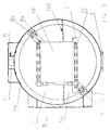
- FIG. 3 is a sectional view of the device along the section line BB 'shown in Fig. 1.
- FIG. 2 also shows the device cut in the axial direction in a perspective view, with cut surfaces being hatched for reasons of clarity.
- the device according to the invention has an essentially cylindrical treatment container 1, which has a controllable liquid outlet 4 and a first suction opening 7 for connecting a vacuum pump to generate a negative pressure in the interior of the treatment container 1. Furthermore, a second suction opening 6 is provided for connecting a further suction device, which essentially serves for the rapid suction of liquid vapors following a cleaning process which can be carried out with the device.
- the further suction device preferably brings about a substantially greater gas exchange than the vacuum pump, but is not suitable for generating a vacuum.
- a workpiece carrier 12 for receiving workpieces is arranged in the interior of the treatment container 1, the workpiece carrier 12 being rotatably mounted in the treatment container 1 about an axis AA ′ running in the longitudinal direction.
- the workpiece carrier 12 serves on the one hand for receiving individual large workpieces and on the other hand for receiving baskets 18 with bulk material, the baskets being liquid and gas permeable.
- a spray unit 8a, 8b for introducing cleaning liquid or a gaseous medium into the interior of the container.
- the spray unit consists of two essentially rectangular pipe loops arranged in parallel, one of which is used to dispense cleaning liquid and the other is used to dispense a gaseous medium.
- the two tube loops 8a, 8b each have a plurality of outlet nozzles directed onto the workpiece carrier.
- the spray unit formed from the two pipe loops 8a, 8b also rotatably mounted about the container axis AA '.
- a closable feed opening 16 is provided on one side of the treatment container 1 for loading the treatment container with workpieces.
- the workpiece carrier 12 has a number of rollers which facilitate the insertion of the basket 18 receiving the workpieces into the treatment container 1.
- the treatment container 1 After the basket 18 carrying the workpieces has been introduced into the treatment container 1, the treatment container 1 is flooded with a cleaning liquid to a predetermined liquid level 100, 102, the workpiece carrier 12 or the basket 18 receiving the workpieces being partially surrounded by the liquid bath 50.
- a cleaning liquid to a predetermined liquid level 100, 102, the workpiece carrier 12 or the basket 18 receiving the workpieces being partially surrounded by the liquid bath 50.
- two different liquid level levels are shown as an example.
- cleaning liquid is introduced into the interior of the container under excess pressure via the outlet nozzles of one of the tube loops of the spray unit 8a, 8b, the cleaning liquid being supplied from the outside via a central shaft 40, via which the workpiece carrier 12 and the spray unit 8a, 8b are also rotatably mounted ,
- the cleaning liquid When the cleaning liquid is introduced into the treatment container 1 under excess pressure, there are essentially three different cleaning processes.
- space 52 above the liquid bath when the liquid jets strike the workpieces, explosive spontaneous evaporation of the treatment liquid occurs, with the energy released releasing contaminants and adhering coating and surface contamination.
- the Pressure of the cleaning liquid which is preferably in the range from 2.0 to 15.0 bar, and the vacuum formed in the space 52, preferably between 0.2 to 0.6 bar, can be coordinated with one another such that it only occurs when the Cleaning liquid on the workpieces evaporates.
- the cleaning liquid is heated to a temperature of approx. 60 to 85 ° C.
- turbulent underwater flows develop due to the introduction of the cleaning liquid, which cause a cleaning effect on the workpieces.
- the workpieces located in the basket 18 are alternately fed to the different cleaning processes in the space 52 above the liquid bath and in the liquid bath 50. Furthermore, by rotating the workpiece carrier 12, the workpiece of the batch located in the basket 18 is permanently mixed in order to expose all the workpieces to the cleaning processes attacking the batch from the outside during the cleaning process. In the space 52 above the liquid bath, the workpieces are acted upon by the rotation of the workpiece carrier 12 from different directions with the liquid jets emerging from the outlet nozzles.
- the spray unit 8a, 8b can remain stationary, part of the pipe loops 8a, 8b being arranged above and part below the liquid level 100, 102 in order to inject cleaning liquid both in the space 52 and in the liquid bath 50.
- the spray unit 8a, 8b is advantageously rotated in the opposite direction to the workpiece carrier 18 about the axis A-A 'during the cleaning process.
- the rotation of the workpiece carrier 12 causes in the liquid bath 50 an additional turbulent flow that enhances the cleaning effect.
- the rotation of the workpiece carrier 12 permanently introduces gas components into the liquid bath 50, which, as gas bubbles of various types, achieve cleaning effects on the workpieces there.
- the boundary area between the gas space 52 and the liquid bath 50 proves to be particularly active in cleaning.
- this transition area between the liquid and gaseous aggregate state there is permanent spontaneous evaporation and condensation, the cleaning liquid in the transition state to the gas phase having a maximum reduced surface tension, which allows the cleaning liquid to penetrate even into capillary gaps and recesses in the workpieces.
- the evaporation of the cleaning liquid in this boundary area is intensified by the cleaning jets which appear on the liquid surface and which cause a permanent swirling up of the liquid surface.
- the liquid vapors accumulating in the gas space 52 are permanently sucked off via the first suction opening 7 by the vacuum pump during the cleaning process.
- a proportion of the liquid bath 50 corresponding to the inflowing amount of cleaning liquid is derived via the liquid outlet 4.
- the liquid drain 4 has a valve, not shown in the figures, which is opened and closed at regular intervals for draining off the liquid.
- the permanent drainage of cleaning liquid from the liquid bath 50 which is replaced by the cleaning liquid supplied via the spray unit 8a, 8b, has the advantage that during the cleaning process dirt that is permanently present the liquid bath 50 accumulates, is discharged.
- the cleaning process described is preferably carried out several times in succession, the liquid bath 50 being drained very quickly at least partially between the individual processes via the liquid drain 4, as a result of which there is a strong suction on the workpieces which entrains dirt residues adhering to the workpieces.
- the draining of the liquid bath 50 is advantageously accelerated by generating an overpressure by means of compressed air introduced via the spray unit.
- the device according to the invention is also suitable for drying the wet workpieces following the cleaning process.
- the cleaning liquid is drained off via the liquid outlet 4 and the liquid outlet 4 is closed.
- a gaseous medium in particular air, is then blown into the treatment container 1 under excess pressure.
- the liquid residues adhering to the workpieces are torn away by the gas jet and evaporate, the liquid vapor that is formed preferably being sucked off by the vacuum pump via the first suction opening 7.
- a negative pressure generated by the vacuum pump in the treatment container 1 also accelerates the evaporation of the liquid residues discharged from the workpieces.
- the workpiece carrier 18 and the tube loop 8b preferably rotate in opposite directions about the axis A-A 'of the treatment container.
- the drying effect is increased by heating the interior of the container, the heating being generated by heating devices (not shown here) attached on the outside or by heat radiators 10a, 10b arranged in the interior of the container.
- the heat radiators are preferably directed onto the workpiece carrier 12 or the workpieces and, as in the FIGS. 1 and 3, as a stationary heat radiator 10a arranged stationary on an inner wall of the container or, as shown in FIG. 4, as a rotatable heat radiator 10b on a pipe loop 8c arranged parallel to the pipe loops 8a, 8b of the spray unit, which together with the spray unit 8a, 8b is rotatably mounted about the axis AA 'of the treatment container.
- the heat radiators 10a, 10b as can be seen in particular from FIG. 1, are designed as elongated elements which extend in the treatment container 1 in the axial direction.
- the liquid vapors still present in the cleaning container 1 from the cleaning process are sucked off via the second suction opening 6. This serves to accelerate the drying process, since the suction device connected to the second suction opening 6 enables a greater gas exchange than the vacuum pump.
- the temperature of the gaseous medium introduced via the spray unit 8a, 8b is between 50 and 200 ° C, accordingly the pressure of the introduced gaseous medium varies between 0.5 bar and 10 bar, with a vacuum inside the container is formed between 0.2 bar and 0.6 bar.
- the device according to the invention also enables a further drying method in which the workpieces are dried by the heat radiation emitted by the heat radiators 10a, 10b in connection with one in the interior of the container the vacuum pump generated vacuum takes place.
- This method is particularly suitable for drying mechanically less resilient components, such as electronic components, which would be destroyed by the high pressure of the gas jets if the drying method described above were used.
- the workpiece carrier 18 rotates in order to expose the workpieces to the heat radiation from all sides. Furthermore, in the device shown in FIG. 4, there is the possibility of rotating the heat radiators 10b through the tube loop 8c around the workpiece carrier 18 and leaving the workpiece carrier 18 stationary, or of rotating the workpiece carrier 18 and the tube loop 8c in opposite directions in order to make the workpieces permanent exposed to heat radiation from different directions.
- the liquid vapor which forms in the interior of the container is drawn off via the first suction opening 7 and the vacuum pump.
- a gaseous medium in particular air
- air is briefly blown into the interior of the container via one of the pipe loops of the spray unit 8a, 8b in order to briefly increase the pressure in the interior of the container and thus reduce the vacuum.
- the air introduced is sucked off via the vacuum pump, the liquid vapors being removed more quickly from the treatment container 1 by this gas exchange, which is increased briefly.
- the introduced air also causes liquid residues to be blown away from the workpieces, so that the adhering liquid residues evaporate more quickly.
Landscapes
- Engineering & Computer Science (AREA)
- Mechanical Engineering (AREA)
- General Engineering & Computer Science (AREA)
- Health & Medical Sciences (AREA)
- Life Sciences & Earth Sciences (AREA)
- Molecular Biology (AREA)
- Cleaning By Liquid Or Steam (AREA)
- Cleaning In General (AREA)
- Drying Of Solid Materials (AREA)
- Cleaning And De-Greasing Of Metallic Materials By Chemical Methods (AREA)
Applications Claiming Priority (3)
| Application Number | Priority Date | Filing Date | Title |
|---|---|---|---|
| DE19714603A DE19714603C1 (de) | 1997-04-09 | 1997-04-09 | Verfahren und Vorrichtung zur Reinigung von Werkstücken |
| DE19714603 | 1997-04-09 | ||
| EP98930632A EP0973620B2 (fr) | 1997-04-09 | 1998-04-08 | Procede et dispositif pour nettoyer ou secher des pieces |
Related Parent Applications (2)
| Application Number | Title | Priority Date | Filing Date |
|---|---|---|---|
| EP98930632A Division EP0973620B2 (fr) | 1997-04-09 | 1998-04-08 | Procede et dispositif pour nettoyer ou secher des pieces |
| EP98930632.9 Division | 1998-10-22 |
Publications (3)
| Publication Number | Publication Date |
|---|---|
| EP1342969A2 true EP1342969A2 (fr) | 2003-09-10 |
| EP1342969A3 EP1342969A3 (fr) | 2006-06-07 |
| EP1342969B1 EP1342969B1 (fr) | 2013-05-29 |
Family
ID=7825878
Family Applications (2)
| Application Number | Title | Priority Date | Filing Date |
|---|---|---|---|
| EP98930632A Expired - Lifetime EP0973620B2 (fr) | 1997-04-09 | 1998-04-08 | Procede et dispositif pour nettoyer ou secher des pieces |
| EP03010727.0A Expired - Lifetime EP1342969B1 (fr) | 1997-04-09 | 1998-04-08 | Procédé et appareil de séchage de pièces |
Family Applications Before (1)
| Application Number | Title | Priority Date | Filing Date |
|---|---|---|---|
| EP98930632A Expired - Lifetime EP0973620B2 (fr) | 1997-04-09 | 1998-04-08 | Procede et dispositif pour nettoyer ou secher des pieces |
Country Status (8)
| Country | Link |
|---|---|
| US (1) | US6253462B1 (fr) |
| EP (2) | EP0973620B2 (fr) |
| AT (1) | ATE246552T1 (fr) |
| AU (1) | AU8101098A (fr) |
| BR (1) | BR9808526A (fr) |
| CA (1) | CA2286102C (fr) |
| DE (2) | DE19714603C1 (fr) |
| WO (1) | WO1998045059A1 (fr) |
Cited By (5)
| Publication number | Priority date | Publication date | Assignee | Title |
|---|---|---|---|---|
| EP1908530A1 (fr) * | 2006-10-02 | 2008-04-09 | Shigayamashita Co., Ltd. | Dispositif pour l'élimination d'eau d'une pièce de travail |
| EP2030699A1 (fr) * | 2007-08-28 | 2009-03-04 | Atec Pharmatechnik Gmbh | Procédé de nettoyage de petits objets |
| RU2426609C1 (ru) * | 2009-12-21 | 2011-08-20 | Сергей Дмитриевич Шестаков | Устройство для поточной сонохимической очистки деталей подшипников качения и способ его переналадки под конкретный типоразмер очищаемой детали |
| CN112974404A (zh) * | 2021-02-23 | 2021-06-18 | 吴小芬 | 一种可以多数量同时进行的全方位五金配件快速清洗装置 |
| CN113883853A (zh) * | 2021-10-20 | 2022-01-04 | 李芃桦 | 一种活性炭酸洗干燥装置 |
Families Citing this family (37)
| Publication number | Priority date | Publication date | Assignee | Title |
|---|---|---|---|---|
| KR100360402B1 (ko) * | 2000-03-22 | 2002-11-13 | 삼성전자 주식회사 | 회전성 분사노즐을 구비하는 웨이퍼 건조 장치 및 이를이용한 웨이퍼 건조 방법 |
| DE10149027B4 (de) * | 2001-10-05 | 2010-05-06 | Mafac Ernst Schwarz Gmbh & Co. Kg | Aufnahmevorrichtung für einen Werkstückträger oder Werkstückkorb in einer Reinigungs- und/oder Trocknungsanlage |
| GB2385315B (en) * | 2002-01-15 | 2004-06-30 | Bespak Plc | Improvements in or relating to valves for dispensers |
| JP2003266030A (ja) * | 2002-03-15 | 2003-09-24 | Seiko Epson Corp | 被処理物の洗浄方法および装置並びにデバイスの製造方法およびデバイス |
| DE10212604B3 (de) * | 2002-03-21 | 2004-01-22 | Mafac Ernst Schwarz Gmbh & Co. Kg | Vorrichtung zur Aufnahme eines Werkstückträgers und zur Zuführung eines ersten und zweiten Mediums und Reinigungsbehälter mit einer solchen Vorrichtung |
| DE10216285B4 (de) * | 2002-04-12 | 2012-03-29 | Mafac Ernst Schwarz Gmbh & Co. Kg Maschinenfabrik | Reinigungsvorrichtung zur Reinigung von Werkstücken |
| US20050020462A1 (en) * | 2003-07-22 | 2005-01-27 | Mark Sanders | System and method for removing coatings from plastic parts |
| DE102004046802B3 (de) * | 2004-09-27 | 2006-04-27 | Mafac Ernst Schwarz Gmbh & Co. Kg Maschinenfabrik | Behandlungsvorrichtung und Verfahren zur reinigenden und/oder trocknenden Behandlung von Werkstücken |
| DE102006039715A1 (de) | 2006-08-24 | 2008-02-28 | Dürr Ecoclean GmbH | Reinigungsvorrichtung mit einer Flutkammer |
| ATE507908T1 (de) | 2008-06-05 | 2011-05-15 | Schwarz Ernst Mafac Gmbh | Behandlungsvorrichtung für werkteile |
| EP2156905B1 (fr) | 2008-08-22 | 2012-06-27 | MAFAC ERNST SCHWARZ GmbH & Co. KG MASCHINENFABRIK | Dispositif de traitement pour pièces d'usinage |
| DE102008051241B4 (de) | 2008-10-10 | 2011-06-16 | Airbus Operations Gmbh | Schalldämpfer für ein Hilfstriebwerk eines Flugzeugs |
| DE102010011738B4 (de) * | 2010-03-17 | 2017-09-14 | Piller Entgrattechnik Gmbh | Waschanlage zum Waschen von Werkstücken |
| CN103464437A (zh) * | 2013-08-23 | 2013-12-25 | 天津港第五港埠有限公司 | 散热器清洗箱 |
| FR3019886B1 (fr) * | 2014-04-14 | 2019-04-05 | Claire MAUREL | Dispositif de sechage de piece et dispositif de lavage de piece utilisant un tel dispositif de sechage |
| DE102014107063B4 (de) * | 2014-05-19 | 2017-02-16 | Mafac Ernst Schwarz Gmbh & Co. Kg Maschinenfabrik | Behandlungsvorrichtung für Werkteile mit einer elektrischen Behandlungseinheit |
| US10112344B2 (en) * | 2015-06-16 | 2018-10-30 | Audubon Machinery Corporation | Machine for removing substrate material, for washing, and for drying parts produced by a 3-D printer |
| DE102016109861A1 (de) * | 2016-05-30 | 2017-11-30 | EMO Oberflächentechnik GmbH | Verfahren und Vorrichtung zur Reinigung von industriell gefertigten Teilen |
| CN106435619A (zh) * | 2016-11-01 | 2017-02-22 | 安徽松羽工程技术设备有限公司 | 一种罐体酸洗电解池 |
| CN106766777A (zh) * | 2017-01-17 | 2017-05-31 | 国际竹藤中心 | 干燥设备 |
| CN107339855B (zh) * | 2017-08-02 | 2023-09-19 | 宜诺(天津)制药设备有限公司 | 一种环式硬带可旋转的直接传导快速连续加热干燥器 |
| KR102586367B1 (ko) | 2017-12-05 | 2023-10-11 | 포스트프로세스 테크놀로지스 인코포레이티드 | 표면 마감 및 서포트 재료 제거를 위한 방법 및 장치(deci duo) |
| US12325189B2 (en) | 2017-12-05 | 2025-06-10 | Postprocess Technologies, Inc. | Vision system and method for apparatus for support removal using directed atomized and semi-atomized fluid |
| US11524464B2 (en) | 2017-12-31 | 2022-12-13 | Postprocess Technologies, Inc. | Method and apparatus for support removal using directed atomized and semi-atomized fluid |
| WO2019143451A1 (fr) | 2017-12-31 | 2019-07-25 | Postprocess Technologies, Inc. | Procédé et appareil d'élimination de support à l'aide d'un fluide atomisé et semi-atomisé dirigé |
| CN109078957A (zh) * | 2018-08-03 | 2018-12-25 | 刘燕 | 一种钢加工废料清洗回收装置 |
| CN109442934A (zh) * | 2018-09-30 | 2019-03-08 | 张红艳 | 一种石油焦加工用烘干机 |
| CN109926397A (zh) * | 2019-04-30 | 2019-06-25 | 苏州能拓新能源有限公司 | 一种清洗烘干设备 |
| JP6808790B1 (ja) * | 2019-09-12 | 2021-01-06 | 株式会社スギノマシン | 洗浄機及び洗浄方法 |
| CN111457701B (zh) * | 2020-04-09 | 2021-09-07 | 扬州文丰机械制造有限公司 | 一种刀片生产中的加热机构 |
| CN112354956A (zh) * | 2020-10-13 | 2021-02-12 | 苏州青众创业服务有限公司 | 一种数控加工用清洗装置 |
| CN112902616A (zh) * | 2021-01-22 | 2021-06-04 | 徐州中辉光伏科技有限公司 | 一种高效率的太阳能光伏板组件加工用烘干装置 |
| CN112923686B (zh) * | 2021-01-28 | 2023-10-03 | 陕西科技大学 | 一种干燥机械装置及方法 |
| CN113865311B (zh) * | 2021-12-01 | 2022-02-18 | 中南大学湘雅医院 | 一种医学器械干燥装置 |
| CN114413581A (zh) * | 2022-02-11 | 2022-04-29 | 亳州普润药业有限公司 | 一种负压式干燥机 |
| CN117207392B (zh) * | 2023-09-18 | 2024-11-05 | 南通大泰塑料制品有限公司 | 一种pvc塑料加工干燥装置 |
| CN117781634A (zh) * | 2023-12-25 | 2024-03-29 | 四川铭丰电子材料科技有限公司 | 一种用于锂电铜箔生产的烘干装置 |
Citations (4)
| Publication number | Priority date | Publication date | Assignee | Title |
|---|---|---|---|---|
| DE2649189A1 (de) | 1975-11-20 | 1977-06-02 | Thuringia Sonneberg Veb | Vorrichtung zum trocknen von gegenstaenden, insbesondere von keramischen formlingen |
| DE3702675A1 (de) | 1987-01-30 | 1988-08-11 | Albrecht Markert Gmbh | Vorrichtung zum nassreinigen von werkstuecken |
| FR2614682A1 (fr) | 1987-04-30 | 1988-11-04 | Giuliani Lando | Procede et dispositif de sechage d'un corps dans lequel une partie de l'humidite a extraire est retenue dans des cellules fermees |
| DE4418608A1 (de) | 1993-05-28 | 1994-12-01 | Mivag Ag | Mikrowellen-Vakuum-Trocknungsvorrichtung sowie Trocknungsverfahren |
Family Cites Families (16)
| Publication number | Priority date | Publication date | Assignee | Title |
|---|---|---|---|---|
| JPS61500952A (ja) * | 1983-12-21 | 1986-05-15 | ゲルゲリイ、ゲルハルト | 粉体又は粒体材料の熱処理方法及び装置 |
| US4983222A (en) * | 1988-04-14 | 1991-01-08 | Union Carbide Chemicals And Plastics Company Inc. | Vapor solvent decontamination of PCB transformer components |
| US5180438A (en) * | 1989-10-11 | 1993-01-19 | Hockh Metall-Reinigungsanlagen Gmbh | Cleaning and drying system |
| DE3943275A1 (de) * | 1989-12-29 | 1991-07-04 | Masch Witte Gmbh & Co Kg | Vorrichtung zur trocknung von schlaemmen, insbesondere klaerschlamm |
| DE4111099C1 (fr) * | 1991-04-05 | 1992-10-15 | Mafac Ernst Schwarz Gmbh & Co. Kg, 7297 Alpirsbach, De | |
| US5702535A (en) * | 1991-11-05 | 1997-12-30 | Gebhard-Gray Associates | Dry cleaning and degreasing system |
| ATA253591A (de) * | 1991-12-20 | 1996-08-15 | Ruebig Ges M B H & Co Kg | Verfahren zum reinigen von werkstücken |
| JPH07103470B2 (ja) * | 1992-03-10 | 1995-11-08 | ミネベア株式会社 | 金属品洗浄方法、金属品洗浄装置及び金属品乾燥装置 |
| DE4302415C1 (de) * | 1993-01-28 | 1993-12-09 | Christ Caroline | Verfahren und Vorrichtung zum Reinigen von Teilen von Kunststoffverarbeitungsmaschinen |
| DE4317862A1 (de) * | 1993-05-28 | 1994-12-01 | Aichelin Ind Ofen | Verfahren und Vorrichtung zum Reinigen von metallischen Werkstücken |
| DE4324432C2 (de) * | 1993-07-21 | 1996-04-25 | Multimatic Oberflaechentechnik | Verfahren zur Reinigung verschmutzter Teile |
| DE4328199C1 (de) * | 1993-08-21 | 1994-10-13 | Duerr Gmbh & Co | Verfahren und Einrichtung zum Trocknen eines nach einer Bearbeitung mit einer Reinigungsflüssigkeit gereinigten Werkstücks |
| DE4330675C2 (de) * | 1993-09-10 | 1997-10-02 | Schwarz Ernst Mafac Gmbh | Trocknungsanlage |
| DE4446587A1 (de) * | 1994-12-24 | 1996-06-27 | Ipsen Ind Int Gmbh | Verfahren zur Reinigung metallischer Werkstücke |
| DE4446588A1 (de) * | 1994-12-24 | 1996-06-27 | Ipsen Ind Int Gmbh | Verfahren zur Reinigung metallischer Werkstücke |
| DE4446589A1 (de) * | 1994-12-24 | 1996-06-27 | Ipsen Ind Int Gmbh | Verfahren zur Reinigung metallischer Werkstücke |
-
1997
- 1997-04-09 DE DE19714603A patent/DE19714603C1/de not_active Expired - Fee Related
-
1998
- 1998-04-08 EP EP98930632A patent/EP0973620B2/fr not_active Expired - Lifetime
- 1998-04-08 CA CA002286102A patent/CA2286102C/fr not_active Expired - Fee Related
- 1998-04-08 AU AU81010/98A patent/AU8101098A/en not_active Abandoned
- 1998-04-08 WO PCT/DE1998/001006 patent/WO1998045059A1/fr not_active Ceased
- 1998-04-08 AT AT98930632T patent/ATE246552T1/de active
- 1998-04-08 US US09/402,940 patent/US6253462B1/en not_active Expired - Lifetime
- 1998-04-08 BR BR9808526-3A patent/BR9808526A/pt not_active IP Right Cessation
- 1998-04-08 DE DE59809214T patent/DE59809214D1/de not_active Expired - Lifetime
- 1998-04-08 EP EP03010727.0A patent/EP1342969B1/fr not_active Expired - Lifetime
Patent Citations (4)
| Publication number | Priority date | Publication date | Assignee | Title |
|---|---|---|---|---|
| DE2649189A1 (de) | 1975-11-20 | 1977-06-02 | Thuringia Sonneberg Veb | Vorrichtung zum trocknen von gegenstaenden, insbesondere von keramischen formlingen |
| DE3702675A1 (de) | 1987-01-30 | 1988-08-11 | Albrecht Markert Gmbh | Vorrichtung zum nassreinigen von werkstuecken |
| FR2614682A1 (fr) | 1987-04-30 | 1988-11-04 | Giuliani Lando | Procede et dispositif de sechage d'un corps dans lequel une partie de l'humidite a extraire est retenue dans des cellules fermees |
| DE4418608A1 (de) | 1993-05-28 | 1994-12-01 | Mivag Ag | Mikrowellen-Vakuum-Trocknungsvorrichtung sowie Trocknungsverfahren |
Cited By (5)
| Publication number | Priority date | Publication date | Assignee | Title |
|---|---|---|---|---|
| EP1908530A1 (fr) * | 2006-10-02 | 2008-04-09 | Shigayamashita Co., Ltd. | Dispositif pour l'élimination d'eau d'une pièce de travail |
| EP2030699A1 (fr) * | 2007-08-28 | 2009-03-04 | Atec Pharmatechnik Gmbh | Procédé de nettoyage de petits objets |
| RU2426609C1 (ru) * | 2009-12-21 | 2011-08-20 | Сергей Дмитриевич Шестаков | Устройство для поточной сонохимической очистки деталей подшипников качения и способ его переналадки под конкретный типоразмер очищаемой детали |
| CN112974404A (zh) * | 2021-02-23 | 2021-06-18 | 吴小芬 | 一种可以多数量同时进行的全方位五金配件快速清洗装置 |
| CN113883853A (zh) * | 2021-10-20 | 2022-01-04 | 李芃桦 | 一种活性炭酸洗干燥装置 |
Also Published As
| Publication number | Publication date |
|---|---|
| CA2286102A1 (fr) | 1998-10-15 |
| EP1342969A3 (fr) | 2006-06-07 |
| AU8101098A (en) | 1998-10-30 |
| EP0973620B1 (fr) | 2003-08-06 |
| US6253462B1 (en) | 2001-07-03 |
| EP0973620B2 (fr) | 2008-06-25 |
| DE19714603C1 (de) | 1998-10-29 |
| CA2286102C (fr) | 2007-09-18 |
| DE59809214D1 (de) | 2003-09-11 |
| EP0973620A1 (fr) | 2000-01-26 |
| ATE246552T1 (de) | 2003-08-15 |
| BR9808526A (pt) | 2000-05-23 |
| EP1342969B1 (fr) | 2013-05-29 |
| WO1998045059A1 (fr) | 1998-10-15 |
Similar Documents
| Publication | Publication Date | Title |
|---|---|---|
| EP0973620B1 (fr) | Procede et dispositif pour nettoyer ou secher des pieces | |
| DE3937221C2 (fr) | ||
| EP0543322B1 (fr) | Procédé pour le nettoyage des parts métalliques | |
| DE2621952C2 (de) | Vorrichtung zum Entplattieren und Reinigen von Plättchen oder Substraten | |
| EP1614150B1 (fr) | Dispositif et procede de nettoyage et de sechage d'objets utilises au cours de la fabrication de semiconducteurs, en particulier, de recipients de transport et de nettoyage pour plaquettes | |
| DE102015105453B4 (de) | Vorrichtung zum trocknen von teilen und vorrichtung zum waschen von teilen unter verwendung einer derartigen trocknungsvorrichtung | |
| DE2304524A1 (de) | Reinigungsvorrichtung fuer metallteile | |
| EP0543318A1 (fr) | Procédé et dispositif pour le nettoyage des parts métalliques | |
| EP0654294A2 (fr) | Procédé et dispositif de filtration de particules solides de liquides et le rinçage du filtre à contre-courant | |
| EP3530364B1 (fr) | Dispositif de nettoyage haute pression pour matériaux sans fin | |
| DE19637086C2 (de) | Automatisch arbeitende Reinigungsanlage für Werkstücke | |
| DE4328199C1 (de) | Verfahren und Einrichtung zum Trocknen eines nach einer Bearbeitung mit einer Reinigungsflüssigkeit gereinigten Werkstücks | |
| EP4504995A1 (fr) | Procédé de passivation d'une surface d'une pièce et dispositif de passivation de pièces | |
| EP2601465B1 (fr) | Utilisation d'un dispositif pour sécher des pièces après un processus de lavage | |
| DE69022427T2 (de) | Verfahren und vorrichtungen für scheideverfahren. | |
| DE2754724A1 (de) | Verfahren und vorrichtung zum trocknen von maschinenteilen | |
| DE4220850C1 (de) | Verfahren und Vorrichtung zum Entfernen von im wesentlichen festen Bestandteilen aus einem Abgasstrom | |
| DE202007016425U1 (de) | Vorrichtung zum Behandeln einer Substratbahn | |
| DE4206181A1 (de) | Vorrichtung zur aufbringung von reinigungsfluessigkeit auf einen zylinder einer rotationsdruckmaschine | |
| EP0580273B1 (fr) | Procédé et dispositif pour la séparation d'agents de traitement liquides des pièces à usines | |
| DE3826273C2 (fr) | ||
| DE2807725C2 (de) | Vakuumtrockner, insbesondere zur Vortrocknung von Substanzen mit einem im Vergleich zur Flüssigkeit geringen Feststoffgehalt | |
| DE19853304C2 (de) | Verfahren zum Trocknen eines Werkstücks | |
| DE10347464B4 (de) | Vorrichtung und Verfahren zum Reinigen und Trocknen von Halbleitererzeugnissen oder von bei der Herstellung von Halbleitererzeugnissen verwendeten Handhabungskörben | |
| EP4516323A1 (fr) | Installation de nettoyage pour le nettoyage de produits et procédé de séchage de produits |
Legal Events
| Date | Code | Title | Description |
|---|---|---|---|
| PUAI | Public reference made under article 153(3) epc to a published international application that has entered the european phase |
Free format text: ORIGINAL CODE: 0009012 |
|
| AC | Divisional application: reference to earlier application |
Ref document number: 0973620 Country of ref document: EP Kind code of ref document: P |
|
| AK | Designated contracting states |
Kind code of ref document: A2 Designated state(s): AT CH DE FR LI |
|
| PUAL | Search report despatched |
Free format text: ORIGINAL CODE: 0009013 |
|
| AK | Designated contracting states |
Kind code of ref document: A3 Designated state(s): AT CH DE FR LI |
|
| RIC1 | Information provided on ipc code assigned before grant |
Ipc: C23G 3/00 20060101ALI20060427BHEP Ipc: F26B 3/04 20060101AFI20030704BHEP Ipc: B08B 3/10 20060101ALI20060427BHEP Ipc: B08B 3/04 20060101ALI20060427BHEP |
|
| 17P | Request for examination filed |
Effective date: 20061206 |
|
| AKX | Designation fees paid |
Designated state(s): AT CH DE FR LI |
|
| 17Q | First examination report despatched |
Effective date: 20081117 |
|
| REG | Reference to a national code |
Ref country code: DE Ref legal event code: R079 Ref document number: 59814525 Country of ref document: DE Free format text: PREVIOUS MAIN CLASS: F26B0003040000 Ipc: F26B0005040000 |
|
| RIC1 | Information provided on ipc code assigned before grant |
Ipc: F26B 7/00 20060101ALI20121030BHEP Ipc: F26B 5/14 20060101ALI20121030BHEP Ipc: F26B 11/18 20060101ALI20121030BHEP Ipc: F26B 5/04 20060101AFI20121030BHEP Ipc: B08B 3/10 20060101ALI20121030BHEP Ipc: B08B 3/04 20060101ALI20121030BHEP |
|
| GRAP | Despatch of communication of intention to grant a patent |
Free format text: ORIGINAL CODE: EPIDOSNIGR1 |
|
| GRAS | Grant fee paid |
Free format text: ORIGINAL CODE: EPIDOSNIGR3 |
|
| GRAP | Despatch of communication of intention to grant a patent |
Free format text: ORIGINAL CODE: EPIDOSNIGR1 |
|
| GRAA | (expected) grant |
Free format text: ORIGINAL CODE: 0009210 |
|
| INTG | Intention to grant announced |
Effective date: 20130404 |
|
| AC | Divisional application: reference to earlier application |
Ref document number: 0973620 Country of ref document: EP Kind code of ref document: P |
|
| AK | Designated contracting states |
Kind code of ref document: B1 Designated state(s): AT CH DE FR LI |
|
| REG | Reference to a national code |
Ref country code: CH Ref legal event code: EP |
|
| REG | Reference to a national code |
Ref country code: AT Ref legal event code: REF Ref document number: 614656 Country of ref document: AT Kind code of ref document: T Effective date: 20130615 |
|
| REG | Reference to a national code |
Ref country code: CH Ref legal event code: NV Representative=s name: R. A. EGLI AND CO. PATENTANWAELTE, CH |
|
| REG | Reference to a national code |
Ref country code: DE Ref legal event code: R096 Ref document number: 59814525 Country of ref document: DE Effective date: 20130725 |
|
| PLBE | No opposition filed within time limit |
Free format text: ORIGINAL CODE: 0009261 |
|
| STAA | Information on the status of an ep patent application or granted ep patent |
Free format text: STATUS: NO OPPOSITION FILED WITHIN TIME LIMIT |
|
| 26N | No opposition filed |
Effective date: 20140303 |
|
| REG | Reference to a national code |
Ref country code: DE Ref legal event code: R097 Ref document number: 59814525 Country of ref document: DE Effective date: 20140303 |
|
| PGFP | Annual fee paid to national office [announced via postgrant information from national office to epo] |
Ref country code: AT Payment date: 20140417 Year of fee payment: 17 Ref country code: DE Payment date: 20140528 Year of fee payment: 17 Ref country code: CH Payment date: 20140422 Year of fee payment: 17 Ref country code: FR Payment date: 20140416 Year of fee payment: 17 |
|
| REG | Reference to a national code |
Ref country code: DE Ref legal event code: R119 Ref document number: 59814525 Country of ref document: DE |
|
| REG | Reference to a national code |
Ref country code: CH Ref legal event code: PL |
|
| REG | Reference to a national code |
Ref country code: AT Ref legal event code: MM01 Ref document number: 614656 Country of ref document: AT Kind code of ref document: T Effective date: 20150408 |
|
| PG25 | Lapsed in a contracting state [announced via postgrant information from national office to epo] |
Ref country code: CH Free format text: LAPSE BECAUSE OF NON-PAYMENT OF DUE FEES Effective date: 20150430 Ref country code: LI Free format text: LAPSE BECAUSE OF NON-PAYMENT OF DUE FEES Effective date: 20150430 Ref country code: DE Free format text: LAPSE BECAUSE OF NON-PAYMENT OF DUE FEES Effective date: 20151103 |
|
| REG | Reference to a national code |
Ref country code: FR Ref legal event code: ST Effective date: 20151231 |
|
| PG25 | Lapsed in a contracting state [announced via postgrant information from national office to epo] |
Ref country code: FR Free format text: LAPSE BECAUSE OF NON-PAYMENT OF DUE FEES Effective date: 20150430 Ref country code: AT Free format text: LAPSE BECAUSE OF NON-PAYMENT OF DUE FEES Effective date: 20150408 |