EP1344445B1 - Bildverarbeitung für Entladungsmittelkontrollsystem - Google Patents
Bildverarbeitung für Entladungsmittelkontrollsystem Download PDFInfo
- Publication number
- EP1344445B1 EP1344445B1 EP03100354A EP03100354A EP1344445B1 EP 1344445 B1 EP1344445 B1 EP 1344445B1 EP 03100354 A EP03100354 A EP 03100354A EP 03100354 A EP03100354 A EP 03100354A EP 1344445 B1 EP1344445 B1 EP 1344445B1
- Authority
- EP
- European Patent Office
- Prior art keywords
- spout
- cap
- image
- control system
- operable
- Prior art date
- Legal status (The legal status is an assumption and is not a legal conclusion. Google has not performed a legal analysis and makes no representation as to the accuracy of the status listed.)
- Expired - Lifetime
Links
- 238000012545 processing Methods 0.000 title description 10
- 230000033001 locomotion Effects 0.000 claims description 46
- 239000000463 material Substances 0.000 claims description 17
- 230000004044 response Effects 0.000 claims description 15
- 238000000034 method Methods 0.000 claims description 13
- 238000006073 displacement reaction Methods 0.000 claims description 8
- 230000008569 process Effects 0.000 claims description 7
- 230000006870 function Effects 0.000 description 13
- 238000010586 diagram Methods 0.000 description 7
- 238000003306 harvesting Methods 0.000 description 7
- 239000004459 forage Substances 0.000 description 3
- 238000012935 Averaging Methods 0.000 description 2
- 238000006243 chemical reaction Methods 0.000 description 2
- 238000004891 communication Methods 0.000 description 2
- 238000001514 detection method Methods 0.000 description 2
- 238000001914 filtration Methods 0.000 description 2
- 238000012544 monitoring process Methods 0.000 description 2
- 241001125929 Trisopterus luscus Species 0.000 description 1
- 230000005540 biological transmission Effects 0.000 description 1
- 230000003139 buffering effect Effects 0.000 description 1
- 230000008859 change Effects 0.000 description 1
- 239000000428 dust Substances 0.000 description 1
- 230000000694 effects Effects 0.000 description 1
- 230000007613 environmental effect Effects 0.000 description 1
- 238000011156 evaluation Methods 0.000 description 1
- 238000012986 modification Methods 0.000 description 1
- 230000004048 modification Effects 0.000 description 1
- 230000003287 optical effect Effects 0.000 description 1
- 238000007781 pre-processing Methods 0.000 description 1
- 238000012360 testing method Methods 0.000 description 1
- 238000004148 unit process Methods 0.000 description 1
Images



Classifications
-
- A—HUMAN NECESSITIES
- A01—AGRICULTURE; FORESTRY; ANIMAL HUSBANDRY; HUNTING; TRAPPING; FISHING
- A01D—HARVESTING; MOWING
- A01D43/00—Mowers combined with apparatus performing additional operations while mowing
- A01D43/06—Mowers combined with apparatus performing additional operations while mowing with means for collecting, gathering or loading mown material
- A01D43/07—Mowers combined with apparatus performing additional operations while mowing with means for collecting, gathering or loading mown material in or into a trailer
- A01D43/073—Mowers combined with apparatus performing additional operations while mowing with means for collecting, gathering or loading mown material in or into a trailer with controllable discharge spout
Definitions
- the invention relates to a spout control system for controlling and aiming a crop delivery spout of a material collecting vehicle with respect to a separate material hauling vehicle moving alongside the collecting vehicle, the control system comprising:
- US 5 749 783 A describes a forage harvester with an unloading spout, to which optical or acoustic sensors measuring a distance to a reflection point are mounted.
- the sensors are oriented toward the filling cone of the product stream and the outer limits of the load container. From the signals of the sensors, adjustment commands are determined that are transmitted to actuators controlling the spout position.
- a system for monitoring loading of products from the spout of a harvester to a separate material hauling vehicle is described in DE 44 26 059 A .
- This system includes a camera mounted on the spout and a video monitor in the cab of the harvester which displays an image to the harvester operator. The spout position is controlled by the operator.
- an automatic control for the rotational angle of the spout around the vertical axis and or the angle of the spout end flap is controlled by an image processing system that attempts to maintain the image of the spout end within the image of the transport vehicle.
- an object of this invention is to provide a system for automatically controlling the spout and cap of a harvesting vehicle with respect to a separate crop-receiving vehicle.
- a spout control system controls and aims a spout and preferably also a cap of a crop harvesting vehicle with respect to a separate crop hauling vehicle moving with the harvesting vehicle.
- the control system includes at least one video camera which is mounted on or near the end of a pivotal cap on an end of the spout and which views a field of view which includes a portion of the hauling vehicle.
- a control unit acting as image processing unit receives an image signal generated by the camera.
- the control unit processes a digital form of the image signal and automatically generates spout and cap control signals as a function thereof.
- Spout and preferably also cap actuators automatically move the spout and the cap in response to the control signal.
- a manual control device for generating a manual spout control signal is also provided.
- the control unit is operable to receive the manual spout control signal and to prevent automatic control of the spout when the manual spout control signal is generated.
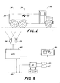
- a material collecting vehicle or crop-gathering vehicle 10 such as a commercially available John Deere 50 Series self-propelled forage harvester, includes a pivotal crop discharge pout 12, which is pivoted by a conventional bi-directional electrohydraulic spout rotating motor 14.
- the spout 12 has a conventional cap 16 pivoted by a conventional cap motor 18.
- a video camera 24 is mounted on or attached to the cap 16 at the end of the spout 12, so as to obtain an image of the field of view in the direction in which material is discharged from the spout 12 and of the crop receiving or hauling vehicle 26, which is shown from the side in Fig. 2 .
- a second video camera 25 may also be mounted on the cap 16. Two cameras may be used to obtain a useable image in case the crop stream would occlude the view of a single camera. In this case, one camera would be mounted on each side of the crop stream. The images from the two cameras can be electronically "stitched" together, or used alternatively.
- the spout 12 discharges material to a material hauling vehicle 26, such as a crop-hauling vehicle 26.
- the camera 24 preferably moves with the cap 16 and is aimed by it.
- the hauling vehicle 26 may have a cover 30 covering a crop-carrying container 32.
- the cover 30 preferably has a side opening 34 which receives crop from the spout 12 as the vehicles 10 and 26 move over terrain.
- the system automatically selects a trackable feature within the field of view of the camera or cameras 24, 25 by any of several known techniques.
- the trackable feature may be a wear pattern, a portion of lettering, a structural element, or other feature.
- the trackable feature can also be a target 33 placed on a relatively featureless surface of the vehicle 26 in a location so that the target 33 is viewable by the camera 24. Additional targets (not shown) could be placed on various locations on the hauling vehicle 26.
- the camera image is analyzed to identify and track the trackable feature.
- the control system includes an electronic signal processing and control unit 40 which controls the timing of image taking and the shutter speeds of the camera 24 and which processes image signals from the camera 24 and in response generates a spout command or control signal which is communicated to electronic control module 21 via bus 46.
- Aiming and pivoting of the spout 12 and the cap 16 may be manually controlled by conventional operator control switches 20 and 22, respectively, which may be mounted on a joystick (not shown) in a cab (not shown) of the harvester 10 or on a control panel (not shown). Switches 20 and 22 are connected to the electronic control module 21 which is also connected to the bus 46.
- the control module 21 receives the automatic control signals from ECU 40 (via bus 46) and receives the manual control signals from switches 20 and 22. Control module 21 then supplies spout and cap control signals to the spout motor 14 and cap motor 18 via the bus 46. Preferably, control module 21 overrides the automatic control signals from the ECU 40 whenever the switches 20, 22 are manually operated. Alternatively, the functions of the ECU 40 and the control module 21 could be integrated into a single control unit. Preferably, the video data is compressed and then decompressed as it is transmitted from one component to another to allow more rapid transmission, analysis and display.
- the camera images may be displayed on a monitor 50 mounted in the cab (not shown) of the vehicle 10.
- the signal delivered to the in-cab monitor 50 may be in either analog or digital format.
- the monitor 50 may be provided as a convenience for the harvest machine operator in initially positioning the discharge spout, but is not necessary for the automatic image capture, analysis, tracking and spout control functions. Because the monitor 50 can be any of a variety of commercially available displays, this feature can be implemented on existing machines with a variety of different display monitors of different types and sizes, and it possible to transmit the captured video image in either digital or analog format as necessary. In either format, the display of the image from camera 24 can be made to occupy either all, or only some part of the display portion of monitor 50 using known techniques.
- the video camera 24 may be a commercially available analog or digital video camera. If a digital camera is used, then the control unit 40 need not digitize the images from the camera. If the captured image is analog, the image information will first be converted by the unit 40 to digital format by standard analog to digital image conversion means. The result is a digital map or image representing the field of view of the camera 24. Preferably, data is transmitted between components in a PCI bus format in order to avoid the limitations of other formats.
- the images from both cameras 24 and 25 can be electronically combined, by, for example, "stitching" the images together using known image processing techniques, so that the control unit 40 provides a single, integrated image covering the overlapping field of view of the cameras 24 and 25, thereby providing a greater image coverage that is possible with the single camera 24.
- the camera control unit 40 also performs a camera selection function.
- Image combining also enhances the capacity of the system to track the stream of crop material in real time to provide for exact placement of crop material regardless of wind drift or changes in trajectory caused by varying crop densities or field conditions.
- Image combining may be accomplished by known techniques such as digitally stitching images together.
- the hauling vehicle 26 and the harvester 10 are initially positioned relative to each other so that the vehicle 26 can receive crop from the harvester 10, and the ECU 40 executes an algorithm or routine as shown in Figs. 4 - 8 .
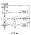
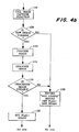
- Figs. 4A and 4B show a simplified overview of the basic or executive signal processing and control algorithm 100 executed by the ECU 40.
- Step 102 executes an initialization routine wherein a stored initialization file is retrieved or created based on operator inputs and system devices are initialized.
- Step 104 reads the inputs to the control system.
- Step 106 in response to a shutdown command, directs the algorithm to step 108 which performs a system shutdown.
- Step 110 in response to a calibration command, directs the algorithm to step 111, which, if a flag is set to ready, directs the algorithm to step 112, else to step 104.
- Step 112 calls a calibration subroutine 200 shown in more detail in Fig. 5 .
- Step 114 in response to an autotrack command, directs the algorithm to step 115, which, if a ready flag is set to ready, directs the algorithm to step 116, else to step 104.
- Step 116 calls an autotracking loop or subroutine 400 shown in more detail in Fig. 8 . Otherwise, the algorithm proceeds to step 118.
- Step 118 calls an image capture routine 300 shown in more detail in Fig. 7 . If the raw captured image is usable, step 120 directs the algorithm to step 122, else to step 128. Step 122 performs various known image processing functions, such as low pass filtering, edge enhancement, thresholding, stripe detection, etc. Step 124 evaluates the processed image to determine if the image includes features which can be used for tracking the movement of the spout 12 relative to the vehicle 26. If in step 126, the processed image is not usable, step 128 generates a not usable message for display or communication to the operator, sets the ready flag to not ready and returns the algorithm to step 104. If the processed image is usable, step 126 directs the algorithm to step 130 which sets the ready flag to ready and returns the algorithm to step 104.
- step 122 performs various known image processing functions, such as low pass filtering, edge enhancement, thresholding, stripe detection, etc.
- Step 124 evaluates the processed image to determine if the image includes features which can be used for tracking the movement
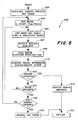
- a pre-operation calibration routine 200 begins at step 202 which initializes or creates in temporary memory, preferably from factory programmed non-volatile memory (not shown), a stored default data table or "jog" table of a set of spout displacement values and a set of spout actuator energizing time values, each spout displacement value representing an amount of spout displacement which would result from energizing the actuator for the corresponding actuator energizing time value.
- Step 204 sets the order of a plurality of spout/cap movement modes to X (spout rotating), X fast (fast spout rotating), Y up (spout cap pivoting upward) and Y down (spout cap pivoting downward), so that these different spout/cap movement modes are calibrated in a certain order, one after the other. These modes can be performed in any order, and the order in which theses modes are performed can be pre-set or can be varied by an operator, if desired.
- Step 206 obtains the next jog table time and direction value.
- Step 207 outputs a spout and cap motion request to the control module 21 which energizes the spout motor 14 and/or the cap motor 18 as shown in Fig. 10 .
- Step 208 calls the image capture routine 300 of Fig. 7 .
- Step 210 analyzes the captured image, determines the actual spout or cap movement and stores the result.
- Step 212 tests for various error conditions, including camera failure, insufficient light, failed communications or end of travel. If an error condition exists, then step 218 generates an operator error message and performs error-handling functions, such as operation retry, system shutdown. If no error condition exists, then step 212 directs the algorithm to step 214, which will return the algorithm to step 206 if the algorithm is not finished with the current movement mode. If all movement modes are not finished, step 216 returns the algorithm to step 204 for calibration with respect to the next movement mode. If all modes are finished, step 220 updates the jog table as a result of repeated operation of step 210. After steps 218 or 220, the algorithm returns to the main algorithm.
- error-handling functions such as operation retry, system shutdown. If no error condition exists, then step 212 directs the algorithm to step 214, which will return the algorithm to step 206 if the algorithm is not finished with the current movement mode. If all movement modes are not finished, step 216 returns the algorithm to step 204 for calibration with respect to the next
- the image capture routine 300 begins at step 302 which, if multiple cameras are in use, identifies which camera is active.
- Step 304 issues camera commands to the active camera to obtain an image or images, to adjust the exposure or to otherwise optimize the captured image.
- Step 305 captures and digitizes one or more images.
- Step 306 manages image buffering or storing, such as, for example, frame averaging of multiple images, or deleting images no longer needed.
- step 308 directs the algorithm to step 310, else to step 316.
- Step 310 processes the image, such as optimizing contrast and brightness levels for display purposes.
- Step 312 adds desired overlay data, such as pointers or text messages.
- Step 314 outputs to the display 50 the processed image resulting from steps 310-312.
- Step 316 performs "intra" image processing functions, such as subsampling (using only some of the pixels in an image to speed up processing when maximum resolution is not needed), rotation, brightness and contrast adjustment. If a lower resolution image is acceptable, the system may capture only the odd or even image lines and then adjust for a proper vertical/horizontal ratio, or it may convert the image to gray scale.
- image processing functions such as subsampling (using only some of the pixels in an image to speed up processing when maximum resolution is not needed), rotation, brightness and contrast adjustment. If a lower resolution image is acceptable, the system may capture only the odd or even image lines and then adjust for a proper vertical/horizontal ratio, or it may convert the image to gray scale.
- Step 318 performs "inter" image-processing functions (over multiple captured images), such as averaging to reduce effects of chaff. These functions are performed on an original image from steps 305 and 306, but not on images processed for display on monitor 50. Step 320 returns the algorithm to the main routine.
- Step 406 performs known image pre-processing functions, such as low pass filtering, edge enhancement, thresholding, stripe detection, etc.
- Step 408 analyzes the captured image and searches the image for a previously selected trackable feature, such as the target 33. The search may involve various known image searching techniques, such as center weighted, last track or brute force techniques. If a target was not found, step 410 directs the algorithm to step 424, else to step 412.
- Step 412 calculates the displacement of the target 33 from its previous position and determines the movements required to move the spout 12 to a desired position.
- Step 414 determines whether or not the required spout movements are within certain limits, such as whether the spout can be moved quickly enough or whether the spout 12 would be driven into engagement with mechanical travel stops (not show). If not, step 414 directs the algorithm to step 428, else to step 416.
- step 416 directs the algorithm to step 418.
- Step 418 uses a stored jog table, as exemplified by the table of Fig. 6 , to obtain the motion commands, which would produce the desired spout motion. Referring to Fig. 6 , for each motion mode, there is stored a set of displacement values corresponding to a set of motor energization time values.
- step 420 then outputs the motion command to the control module 21 which energizes the spout motor 14 and/or the cap motor 18 as shown in Fig. 10 .
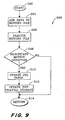
- step 416 If, in step 416, the required spout motion is finished step 416 directs the algorithm to step 422 which calls an auto-calibration routine 500 shown in Fig. 9 . After step 422, routine 400 returns at step 430.
- Step 424 increments a desired number of dead-reckoning passes, where a "dead reckoning pass" means an execution of the algorithm during which no spout or cap movement is commanded.
- a limit number of dead-reckoning passes is stored upon startup of the system, and this limit number can be adjusted by an operator. If the limit number of dead reckoning passes is exceeded, step 426 directs the algorithm to step 428, else to step 430. Step 428 disables automatic spout control and sends a warning message to the operator. After step 428, routine 400 returns at step 430.
- routine 400 processes the image from the camera 24 to determine if it contains an image of the previously selected trackable feature, such as target 33. If the image contains an image of the trackable feature, routine 400 determines whether or not the spout 12 (or cap 16) must be moved in response to movement of the trackable feature within the image. If so, a spout movement command is obtained from the stored jog table routine (step 418) and this spout movement command is sent to control unit 21 (step 420), which then moves the spout, or cap or both accordingly.
- step 422 calls the autocalibration routine 500 which determines whether or not the jog table should be updated as a result of this most recent movement of the spout and/or cap. In this manner the stored jog table is continually updated during operation of the system in order to adjust for changes which can occur over time.
- the auto-calibration routine 500 begins at step 502.
- Step 504 adds the most recent motion command and spout/cap movement results data to a history file which is stored in the ECU 40.
- Step 506 analyzes the information in the history file, such as performing a trend analysis on the information.
- Step 508 determines whether or not the resulting spout or cap movement deviates significantly from the desired spout or cap movement. If not, step 508 directs the algorithm to step 514. If yes, step 508 directs the algorithm to step 510 which updates the jog table according to the results of the analysis performed in step 506.
- Step 512 updates the jog table stored in the non-volatile memory (not shown). Then, the routine 500 returns at 514.
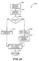
- the control module 21 executes an algorithm 600, and in step 602 receives a motion request from the ECU 40, as in steps 207 of Fig. 5 and step 420 of Fig. 8 .
- Step 604 decodes the received motion request. If there is a conflict between the decoded motion request and a manual motion command via switches 20 or 22, then step 606 directs the algorithm to step 608.
- Step 608 sets the ready flag equal to not ready, step 610 formulates an operator motion command, and step 614 outputs this operator motion command to the spout and cap motors 14 and 18.
- step 606 directs the algorithm to step 612.
- step 612 formulates an automatic motion command
- step 614 outputs this automatic motion command to the spout and cap motors 14 and 18.
- the algorithm returns or continues at step 616.
- the system described herein obtains and processes an image of the trackable feature on the hauling vehicle 26, and in response, generates spout steering and cap pivoting control signals which are communicated to the electrohydraulic spout motor 14 and to cap motor 18 to pivot the spout 12 in response to a change in the position of the selected target elements, if there is a movement of those elements relative to the camera's field of view during the automatic tracking mode.
- control unit 21 causes control unit 40 to operate in a subservient fashion with respect to manual control of the spout 12 via the spout control switches 20, 22, and will drop out of its automatic tracking mode and revert to the automatic image capture mode and target selection mode whenever the operator exercises manual control over the spout 12.
- the control unit 40 could also automatically returns to the automatic tracking mode upon the release of the switches 20, 22 by the operator following any manual interruption of the automatic tracking mode.
- the operator may interrupt automatic control by using the switches 20, 22 (during which the auto target select function continues to operate).
- the control unit 40 reverts back to its auto track function and tracks the most recently selected "best target" in the last obtained image.
- this spout control system is capable of operating in a stand-alone fashion such that there is no need for input from the driver of the hauling vehicle 26, and the driver of the hauling vehicle 26 need only maintain an approximate position relative to the harvester 10.
- control unit 40 may be programmed to track multiple target elements in the field(s) of view of either or both cameras 24 and 25 in order to provide a control system which has an enhanced, image fault tolerance capacity, wherein the system can track one or more images concurrently and continue in its automatic tracking mode as long as at least one target image remains unobscured by dust, chaff or other environmental conditions.
- the invention can be applied to any system where a steerable spout is used to deliver material to relatively movable material receiving unit.
- the invention can be applied to a crop delivery spout, which delivers crop to a top-loading crop hauling vehicle with the addition of edge tracking capability to use an edge of the hauling vehicle as the trackable feature.
Landscapes
- Life Sciences & Earth Sciences (AREA)
- Environmental Sciences (AREA)
- Guiding Agricultural Machines (AREA)
- Harvester Elements (AREA)
Claims (16)
- Auswurfsteuersystem zum Steuern und Ausrichten eines Erntegutförderauswurfes (12) eines Materialsammelfahrzeugs (10) bezüglich eines separaten Materialbeförderungsfahrzeugs (26), das sich längs des Sammelfahrzeugs (10) bewegt, wobei das Steuersystem folgendes umfaßt:eine Bildeinrichtung, die dafür ausgelegt ist, ein Blickfeld zu sehen, das einen Abschnitt des Beförderungsfahrzeugs (26) enthält, und ein Bildsignal zu erzeugen;eine Steuereinheit (40), die dafür ausgelegt ist, das Bildsignal zu empfangen, das Bildsignal zu verarbeiten und automatisch ein Auswurfbefehlssignal als Funktion davon zu erzeugen;einen Aktuator (14), der dafür ausgelegt ist, den Auswurf (12) als Reaktion auf das Auswurfbefehlssignal automatisch zu bewegen; undeine Handsteuereinrichtung zum Erzeugen eines Handauswurfsteuersignals, wobei die Steuereinheit (40) betätigt werden kann, das Handauswurfsteuersignal zu empfangen;dadurch gekennzeichnet, daß die Steuereinheit (40) angesteuert werden kann, eine automatische Steuerung des Ausgusses (12) zu verhindern, wenn das Handauswurfsteuersignal erzeugt wird.
- Auswurfsteuersystem nach Anspruch 1, dadurch gekennzeichnet, daß die Bildeinrichtung eine in der Nähe eines Endes des Auswurfs (12) befestigte Videokamera (24, 25) umfaßt.
- Auswurfsteuersystem nach Anspruch 1 oder 2, dadurch gekennzeichnet, daß eine Kappe (16) schwenkbar an einem Ende des Auswurfs (12) befestigt ist und daß die Bildeinrichtung eine an der Kappe (16) befestigte Videokamera (24) umfaßt.
- Auswurfsteuersystem nach einem der Ansprüche 1 bis 3, dadurch gekennzeichnet, daß die Steuereinheit (40) betätigt werden kann, um ein Merkmal in dem Bild zu identifizieren und das Befehlssignal zu erzeugen, um zu bewirken, daß der Aktuator (14) den Auswurf (12) im wesentlichen in einer bestimmten Richtung relativ zu dem Merkmal ausgerichtet hält.
- Auswurfsteuersystem nach Anspruch 4, dadurch gekennzeichnet, daß das Merkmal ein an dem Beförderungsfahrzeug plaziertes Ziel (33) ist.
- Auswurfsteuersystem nach einem der Ansprüche 1 bis 5, dadurch gekennzeichnet, daß die Steuereinheit (40) betätigt werden kann, um die mehreren Merkmale in dem Bild zu identifizieren, und wenn ein bestimmtes Merkmal verdeckt wird, das Befehlssignal zu erzeugen, um zu bewirken, daß der Aktuator (14) den Auswurf (12) im wesentlichen in der Richtung relativ zu einem unverdeckten der Merkmale ausgerichtet hält.
- Auswurfsteuersystem nach einem der Ansprüche 1 bis 6, dadurch gekennzeichnet, daß die Steuereinheit (40) betätigt werden kann, um eine automatische Bewegung des Auswurfs (12) zu verhindern, wenn der Auswurf (12) als Reaktion auf eine Operatormanipulation der Handsteuereinrichtung gesteuert wird; und die Steuereinheit (40) eine automatische Bewegung des Auswurfs (12) gestattet, wenn die Handsteuereinrichtung für eine bestimmte Zeitperiode nicht manipuliert wird.
- Auswurfsteuersystem nach einem der Ansprüche 1 bis 7, dadurch gekennzeichnet, daß eine Kappe (16) schwenkbar an einem Ende des Auswurfs (12) befestigt ist; daß ein Kappenaktuator (18) betätigt werden kann, um die Kappe (16) als Reaktion auf ein Kappenbefehlssignal relativ zu dem Auswurf (12) zu schwenken; und daß die Steuereinheit (40) betätigt werden kann, um das Bildsignal zu empfangen und das Kappenbefehlssignal als Funktion davon automatisch zu erzeugen.
- Auswurfsteuersystem nach einem der Ansprüche 1 bis 8, dadurch gekennzeichnet, daß die Steuereinheit (40) betätigt werden kann, um eine Datentabelle zu erzeugen, die einen Satz von Auswurfverlagerungswerten und einen Satz von Auswurfaktuatorbestromungszeitwerten enthält, wobei jeder Auswurfverlagerungswert ein Ausmaß an Auswurfverlagerung darstellt, das sich aus dem Bestromen des Aktuators für den entsprechenden Aktuatorbestromungszeitwert ergeben würde, und daß die Steuereinheit betätigt werden kann, um ein Auswurfbefehlssignal automatisch als eine Funktion erfaßter Parameter und eines der gespeicherten Auswurfaktuatorbestromungszeitwerte zu erzeugen.
- Auswurfsteuersystem nach Anspruch 9, dadurch gekennzeichnet, daß die Steuereinheit betätigt werden kann, um die Datentabelle zu aktualisieren, nachdem ein Befehlssignal oder mehrere Befehlssignale an den Aktuator (14) angelegt sind.
- Auswurfsteuersystem nach Anspruch 9, dadurch gekennzeichnet, daß die Steuereinheit (40) betätigt werden kann, um die Datentabelle nur dann zu aktualisieren, wenn eine tatsächliche Bewegung des Auswurfs (12) signifikant von einer gewünschten Auswurfbewegung abweicht.
- Auswurfsteuersystem nach einem der Ansprüche 9 bis 11, dadurch gekennzeichnet, daß die Steuereinheit (40) betätigt werden kann, um eine Datentabelle zu erzeugen, die mehrere Auswurfbewegungsmodi darstellt.
- Auswurfsteuersystem nach Anspruch 12, dadurch gekennzeichnet, daß die Auswurfbewegungsmodi einen normalen Auswurfdrehgeschwindigkeitsmodus und einen schnellen Auswurfdrehgeschwindigkeitsmodus umfassen.
- Auswurfsteuersystem nach einem der Ansprüche 10 bis 13, dadurch gekennzeichnet, daß eine Kappe (16) schwenkend an einem Ende des Auswurfs (12) befestigt ist, daß ein Kappenaktuator (18) betätigt werden kann, um die Kappe (16) als Reaktion auf ein Kappenbefehlssignal relativ zu dem Auswurf zu schwenken; und daß die Steuereinheit (40) betätigt werden kann, um eine Datentabelle zu erzeugen, die mehrere Bewegungsmodi für Auswurf (12) und Kappe (16) darstellt, so daß die Auswurf- und Kappenbewegungsmodi in einer gewissen Reihenfolge nacheinander kalibriert werden.
- Auswurfsteuersystem nach Anspruch 14, dadurch gekennzeichnet, daß die Bewegungsmodi einen Kappenaufwärtsschwenkmodus und einen Kappenabwärtsschwenkmodus umfassen.
- Auswurfsteuersystem nach einem der Ansprüche 1 bis 15, dadurch gekennzeichnet, daß es ein Paar Bildeinrichtungen mit überlappenden Blickfeldern umfaßt, die einen Abschnitt des Beförderungsfahrzeugs (20) enthalten, wobei jede Bildeinrichtung ein Bildsignal erzeugt, und daß die Steuereinheit (40) betätigt werden kann, um die Bildsignale zu empfangen, daraus ein kombiniertes Bild auszubilden, das kombinierte Bild zu verarbeiten und automatisch ein Auswurfbefehlssignal als Funktion davon zu erzeugen; und daß der Aktuator (14) betätigt werden kann, um den Auswurf (12) als Reaktion auf das Auswurfbefehlssignal automatisch zu bewegen.
Priority Applications (1)
| Application Number | Priority Date | Filing Date | Title |
|---|---|---|---|
| DE60319618T DE60319618T3 (de) | 2002-03-13 | 2003-02-17 | Bildverarbeitung für Entladungsmittelkontrollsystem |
Applications Claiming Priority (2)
| Application Number | Priority Date | Filing Date | Title |
|---|---|---|---|
| US10/096,769 US6943824B2 (en) | 2002-03-13 | 2002-03-13 | Image processing spout control system |
| US96769 | 2002-03-13 |
Publications (3)
| Publication Number | Publication Date |
|---|---|
| EP1344445A1 EP1344445A1 (de) | 2003-09-17 |
| EP1344445B1 true EP1344445B1 (de) | 2008-03-12 |
| EP1344445B2 EP1344445B2 (de) | 2012-03-14 |
Family
ID=27765405
Family Applications (1)
| Application Number | Title | Priority Date | Filing Date |
|---|---|---|---|
| EP03100354A Expired - Lifetime EP1344445B2 (de) | 2002-03-13 | 2003-02-17 | Bildverarbeitung für Entladungsmittelkontrollsystem |
Country Status (6)
| Country | Link |
|---|---|
| US (1) | US6943824B2 (de) |
| EP (1) | EP1344445B2 (de) |
| AU (1) | AU2003201276A1 (de) |
| BR (1) | BR0300555A (de) |
| DE (1) | DE60319618T3 (de) |
| NZ (1) | NZ524701A (de) |
Families Citing this family (166)
| Publication number | Priority date | Publication date | Assignee | Title |
|---|---|---|---|---|
| FI111836B (fi) * | 2001-04-17 | 2003-09-30 | Sandvik Tamrock Oy | Menetelmä ja laitteisto dumpperin automaattiseksi kuormaamiseksi |
| DE102004052298A1 (de) * | 2004-10-06 | 2006-06-08 | Claas Selbstfahrende Erntemaschinen Gmbh | Überladeassistenzsystem |
| EP1671530B1 (de) * | 2004-12-18 | 2008-01-16 | Deere & Company | Erntemaschine |
| US20060271262A1 (en) * | 2005-05-24 | 2006-11-30 | Mclain Harry P Iii | Wireless agricultural network |
| US7697827B2 (en) | 2005-10-17 | 2010-04-13 | Konicek Jeffrey C | User-friendlier interfaces for a camera |
| US8930089B2 (en) * | 2006-05-25 | 2015-01-06 | Barry H. Reeves | System and method for indicating to a remote location operation of an auger or the like |
| US20070288147A1 (en) * | 2006-05-25 | 2007-12-13 | Reeves Barry H | System and method for indicating to a remote location operation of an auger or the like |
| DE102007009666A1 (de) * | 2007-02-22 | 2008-08-28 | Carl Zeiss Microimaging Gmbh | Anordnung zum Befüllen eines Behälters mit Schüttgut |
| DE202007005756U1 (de) * | 2007-04-19 | 2008-08-28 | Wirtgen Gmbh | Selbstfahrende Baumaschine |
| US8260499B2 (en) * | 2007-05-01 | 2012-09-04 | Deere & Company | Automatic steering system and method for a work vehicle with feedback gain dependent on a sensed payload |
| EP2020174B1 (de) | 2007-08-03 | 2012-02-29 | AGROCOM GmbH & Co. Agrarsystem KG | Landwirtschaftliche Arbeitsmaschine |
| US7677169B2 (en) | 2007-09-06 | 2010-03-16 | Cnh America Llc | Apparatus and method using imaging in building a cotton module |
| DE102008008260B4 (de) | 2008-02-08 | 2010-09-09 | Wirtgen Gmbh | Steuerung einer Gewinnungsmaschine und Gewinnungsmaschine |
| DE102008014001A1 (de) * | 2008-03-13 | 2009-09-17 | Claas Selbstfahrende Erntemaschinen Gmbh | Landwirtschaftliche Erntemaschine mit einer Überladeeinrichtung |
| DE102008002006A1 (de) * | 2008-05-27 | 2009-12-03 | Deere & Company, Moline | Steueranordnung zur Kontrolle des Überladens landwirtschaftlichen Ernteguts von einer Erntemaschine auf ein Transportfahrzeug |
| PL2138027T5 (pl) * | 2008-06-25 | 2018-11-30 | Claas E-Systems Kgaa Mbh & Co Kg | Urządzenie transferowe i pojazd rolniczy |
| US8280595B2 (en) * | 2008-08-12 | 2012-10-02 | Cnh America Llc | System and method employing short range communications for communicating and exchanging operational and logistical status information among a plurality of agricultural machines |
| CA2771547C (en) * | 2008-08-18 | 2016-12-06 | Neil T. Mylet | Monitoring and control system for commodity loading |
| US8954187B1 (en) * | 2008-08-18 | 2015-02-10 | Loadout Technologies LLC | Social network and safety features for process control systems |
| US9235214B2 (en) * | 2008-09-11 | 2016-01-12 | Deere & Company | Distributed knowledge base method for vehicular localization and work-site management |
| US9188980B2 (en) * | 2008-09-11 | 2015-11-17 | Deere & Company | Vehicle with high integrity perception system |
| US8195342B2 (en) * | 2008-09-11 | 2012-06-05 | Deere & Company | Distributed knowledge base for vehicular localization and work-site management |
| US8195358B2 (en) | 2008-09-11 | 2012-06-05 | Deere & Company | Multi-vehicle high integrity perception |
| US8989972B2 (en) | 2008-09-11 | 2015-03-24 | Deere & Company | Leader-follower fully-autonomous vehicle with operator on side |
| US8478493B2 (en) * | 2008-09-11 | 2013-07-02 | Deere & Company | High integrity perception program |
| US9026315B2 (en) | 2010-10-13 | 2015-05-05 | Deere & Company | Apparatus for machine coordination which maintains line-of-site contact |
| US8818567B2 (en) * | 2008-09-11 | 2014-08-26 | Deere & Company | High integrity perception for machine localization and safeguarding |
| US20100063652A1 (en) * | 2008-09-11 | 2010-03-11 | Noel Wayne Anderson | Garment for Use Near Autonomous Machines |
| US8392065B2 (en) * | 2008-09-11 | 2013-03-05 | Deere & Company | Leader-follower semi-autonomous vehicle with operator on side |
| US8224500B2 (en) * | 2008-09-11 | 2012-07-17 | Deere & Company | Distributed knowledge base program for vehicular localization and work-site management |
| US8229618B2 (en) * | 2008-09-11 | 2012-07-24 | Deere & Company | Leader-follower fully autonomous vehicle with operator on side |
| US8145393B2 (en) * | 2008-09-17 | 2012-03-27 | Cnh America Llc | System and method employing short range communications for interactively coordinating unloading operations between a harvester and a grain transport |
| US8639408B2 (en) * | 2008-10-15 | 2014-01-28 | Deere & Company | High integrity coordination system for multiple off-road vehicles |
| US8437901B2 (en) * | 2008-10-15 | 2013-05-07 | Deere & Company | High integrity coordination for multiple off-road vehicles |
| US8126620B2 (en) * | 2009-04-28 | 2012-02-28 | Cnh America Llc | Grain transfer control system and method |
| DE102009027245A1 (de) * | 2009-06-26 | 2010-12-30 | Deere & Company, Moline | Steueranordnung zur Kontrolle des Überladens landwirtschaftlichen Ernteguts von einer Erntemaschine auf ein Transportfahrzeug |
| US20110055899A1 (en) * | 2009-08-28 | 2011-03-03 | Uplogix, Inc. | Secure remote management of network devices with local processing and secure shell for remote distribution of information |
| PL2311307T3 (pl) | 2009-09-07 | 2012-09-28 | Claas E Systems Gmbh | Wskaźnik stopnia napełnienia, pojazd rolniczy zawierający taki wskaźnik oraz sposób kontroli napełniania obszaru docelowego |
| ATE533350T1 (de) * | 2009-09-07 | 2011-12-15 | Claas Agrosystems Gmbh & Co Kg | Steuerungssystem eines landwirtschaftlichen fahrzeugs mit einem güterträger, landwirtschaftliches fahrzeug und verfahren zur steuerung eines güterträgers des landwirtschaftlichen fahrzeugs |
| US9345194B2 (en) * | 2009-09-30 | 2016-05-24 | Cnh Industrial America Llc | Automatic display of remote camera image |
| BE1019192A3 (nl) | 2010-02-21 | 2012-04-03 | Cnh Belgium Nv | Werkwijze voor het richten van een ontlaadtoestel van een oogstmachine naar een container. |
| US8451139B2 (en) * | 2010-02-22 | 2013-05-28 | Cnh America Llc | System and method for coordinating harvester and transport vehicle unloading operations |
| US8380401B2 (en) | 2010-06-09 | 2013-02-19 | Cnh America Llc | Automatic grain transfer control system based on real time modeling of a fill level profile for regions of the receiving container |
| DE102010038661B4 (de) * | 2010-07-29 | 2020-07-02 | Deere & Company | Erntemaschine mit einem an einem Fluggerät befestigten Sensor |
| US8789563B2 (en) * | 2010-10-12 | 2014-07-29 | Deere & Company | Intelligent grain bag loader |
| US9002591B2 (en) * | 2011-02-18 | 2015-04-07 | Cnh Industrial America Llc | Harvester spout control system and method |
| DE102011002111A1 (de) | 2011-04-15 | 2012-10-18 | Claas Selbstfahrende Erntemaschinen Gmbh | Kamera zur Überwachung von Maschinenfunktionen eines Fahrzeugs sowie Verwendung einer Kamera |
| DE102011002071A1 (de) * | 2011-04-15 | 2012-10-18 | Claas Selbstfahrende Erntemaschinen Gmbh | System und Verfahren zur Steuerung der Erntegutüberladung |
| US9560808B2 (en) | 2011-04-19 | 2017-02-07 | Cnh Industrial America Llc | System for controlling bale forming and wrapping operations |
| DE102011050629A1 (de) * | 2011-05-25 | 2012-11-29 | Claas Selbstfahrende Erntemaschinen Gmbh | Erntevorrichtung |
| DE102011082052B4 (de) | 2011-09-02 | 2015-05-28 | Deere & Company | Anordnung und Verfahren zur selbsttätigen Überladung von Erntegut von einer Erntemaschine auf ein Transportfahrzeug |
| US8626406B2 (en) | 2011-12-22 | 2014-01-07 | Deere & Company | Method and system for transferring material between vehicles |
| US9861040B2 (en) | 2012-02-10 | 2018-01-09 | Deere & Company | Method and stereo vision system for facilitating the unloading of agricultural material from a vehicle |
| US9522791B2 (en) * | 2012-02-10 | 2016-12-20 | Carnegie Mellon University, A Pennsylvania Non-Profit Corporation | System and method of material handling using one or more imaging devices on the transferring vehicle to control the material distribution into the storage portion of the receiving vehicle |
| US8649940B2 (en) | 2012-02-10 | 2014-02-11 | Deere & Company | Method and stereo vision system for managing the unloading of an agricultural material from a vehicle |
| US9392746B2 (en) | 2012-02-10 | 2016-07-19 | Deere & Company | Artificial intelligence for detecting and filling void areas of agricultural commodity containers |
| US8868304B2 (en) * | 2012-02-10 | 2014-10-21 | Deere & Company | Method and stereo vision system for facilitating the unloading of agricultural material from a vehicle |
| DE102012008986B4 (de) * | 2012-05-04 | 2023-08-31 | Connaught Electronics Ltd. | Kamerasystem mit angepasster ROI, Kraftfahrzeug und entsprechendes Verfahren |
| DE102012215013A1 (de) | 2012-08-23 | 2014-02-27 | Wirtgen Gmbh | Selbstfahrende Fräsmaschine, sowie Verfahren zum Abladen von Fräsgut |
| DE102012215005A1 (de) | 2012-08-23 | 2014-02-27 | Wirtgen Gmbh | Selbstfahrende Fräsmaschine, sowie Verfahren zum Lenken einer selbstfahrenden Fräsmaschine |
| US9326444B2 (en) * | 2013-02-08 | 2016-05-03 | Deere & Company | Method and stereo vision system for facilitating the unloading of agricultural material from a vehicle |
| EP2792229B1 (de) | 2013-04-02 | 2016-03-23 | Deere & Company | Steueranordnung und Verfahren zur Steuerung der Position einer Vorrichtung einer Erntemaschine |
| US9992932B2 (en) | 2013-04-02 | 2018-06-12 | Deere & Company | Control arrangement and method for controlling a position of a transfer device of a harvesting machine |
| US10129528B2 (en) | 2013-04-02 | 2018-11-13 | Deere & Company | Control arrangement and method for controlling a position of a transfer device of a harvesting machine |
| DE102014105643B4 (de) * | 2013-04-22 | 2026-01-22 | Carnegie Mellon University | System und Verfahren zur Verbesserung der Robustheit eines automatisierten Entladesystems |
| JP6086536B2 (ja) * | 2013-05-31 | 2017-03-01 | ヤンマー株式会社 | 農作物排出装置 |
| JP6202491B2 (ja) * | 2013-05-31 | 2017-09-27 | ヤンマー株式会社 | 農作物排出装置及び走行型収穫機 |
| JP6086534B2 (ja) * | 2013-05-31 | 2017-03-01 | ヤンマー株式会社 | 農作物排出装置 |
| CA2821182A1 (en) * | 2013-07-17 | 2015-01-17 | Sheldon Affleck | Method and apparatus for loading railcars with crop material |
| BE1021158B1 (nl) * | 2013-07-24 | 2015-10-30 | Cnh Industrial Belgium Nv | Oogstmachines voor gebruik in de landbouw |
| BE1021106B1 (nl) | 2013-09-03 | 2016-03-15 | Cnh Industrial Belgium Nv | Ontlaadtoestellen voor oogstmachines voor gebruik in de landbouw |
| BE1021164B1 (nl) | 2013-10-28 | 2016-01-18 | Cnh Industrial Belgium Nv | Ontlaadsystemen |
| DE102013018724B4 (de) * | 2013-11-08 | 2015-09-03 | LASE Industrielle Lasertechnik GmbH | Landwirtschaftliche Erntemaschine |
| BE1021167B1 (nl) * | 2013-12-10 | 2016-01-14 | Cnh Industrial Belgium Nv | Sensoropstelling |
| BR102015013229B8 (pt) * | 2014-06-13 | 2021-12-14 | Cnh Ind America Llc | Sistema de controle para um veículo agrícola e método para calibrar o alinhamento de uma saída do transportador de um veículo agrícola com um compartimento de armazenamento |
| BR102015013228B1 (pt) | 2014-06-13 | 2020-11-24 | Cnh Industrial America Llc | SISTEMA E METODO DE CONTROLE PARA UM VEfCULO AGRiCOLA |
| DE102014216603B4 (de) | 2014-08-21 | 2018-02-22 | Wirtgen Gmbh | Selbstfahrende Fräsmaschine, sowie Verfahren zum Abladen von Fräsgut |
| DE102014216763B4 (de) * | 2014-08-22 | 2018-07-26 | Wirtgen Gmbh | Selbstfahrende Fräsmaschine, sowie Verfahren zum Abladen von Fräsgut |
| DE102014216713B4 (de) | 2014-08-22 | 2018-09-06 | Wirtgen Gmbh | Selbstfahrende Fräsmaschine, sowie Verfahren zum Abladen von Fräsgut |
| CN105692098A (zh) * | 2014-11-25 | 2016-06-22 | 无锡市洗选设备厂 | 偏角信号采集式砂石输送装置 |
| US10834872B2 (en) * | 2015-07-02 | 2020-11-17 | Cnh Industriall America Llc | Unload spout inclination limit adjust system and method |
| EP3165078B1 (de) * | 2015-11-06 | 2020-04-22 | Exel Industries | Erntetransfervorrichtung und entsprechendes verfahren |
| EP3175699B1 (de) * | 2015-12-01 | 2019-02-06 | AGCO International GmbH | Erntemaschinenanzeigesystem |
| US10019790B2 (en) | 2016-01-15 | 2018-07-10 | Deere & Company | Fill level indicator for an automated unloading system |
| US20180022559A1 (en) * | 2016-07-22 | 2018-01-25 | Scott William Knutson | Loader Positioning System |
| DE102016116043A1 (de) * | 2016-08-29 | 2018-03-01 | Claas Selbstfahrende Erntemaschinen Gmbh | Transportfahrzeug |
| US10159191B2 (en) * | 2016-09-23 | 2018-12-25 | Deere & Company | Harvester grain unloader |
| DE102016222589B4 (de) | 2016-11-16 | 2020-01-16 | Wirtgen Gmbh | Selbstfahrende Fräsmaschine, sowie Verfahren zum Steuern einer selbstfahrenden Fräsmaschine |
| US10351172B2 (en) | 2017-02-28 | 2019-07-16 | Brandt Agricultural Products Ltd. | Tandem steering for a grain cart |
| US10377290B2 (en) | 2017-02-28 | 2019-08-13 | Brandt Agricultural Products Ltd. | Spout autorotate for a grain cart |
| US10278328B2 (en) | 2017-02-28 | 2019-05-07 | Brandt Agricultural Products Ltd. | Grain cart with automatic unloading of a predetermined weight of crop material |
| DE102017220869A1 (de) | 2017-11-22 | 2019-05-23 | Wirtgen Gmbh | Selbstfahrende Fräsmaschine, Verfahren zum automatischen Beladen eines Transportmittels mit Fräsgut, sowie Straßen- oder Bodenbearbeitungseinheit |
| US11672203B2 (en) | 2018-10-26 | 2023-06-13 | Deere & Company | Predictive map generation and control |
| US11589509B2 (en) | 2018-10-26 | 2023-02-28 | Deere & Company | Predictive machine characteristic map generation and control system |
| US11467605B2 (en) | 2019-04-10 | 2022-10-11 | Deere & Company | Zonal machine control |
| US11641800B2 (en) | 2020-02-06 | 2023-05-09 | Deere & Company | Agricultural harvesting machine with pre-emergence weed detection and mitigation system |
| US11957072B2 (en) | 2020-02-06 | 2024-04-16 | Deere & Company | Pre-emergence weed detection and mitigation system |
| US11178818B2 (en) | 2018-10-26 | 2021-11-23 | Deere & Company | Harvesting machine control system with fill level processing based on yield data |
| US11240961B2 (en) | 2018-10-26 | 2022-02-08 | Deere & Company | Controlling a harvesting machine based on a geo-spatial representation indicating where the harvesting machine is likely to reach capacity |
| US11653588B2 (en) | 2018-10-26 | 2023-05-23 | Deere & Company | Yield map generation and control system |
| US12069978B2 (en) | 2018-10-26 | 2024-08-27 | Deere & Company | Predictive environmental characteristic map generation and control system |
| US11079725B2 (en) | 2019-04-10 | 2021-08-03 | Deere & Company | Machine control using real-time model |
| DE102019104218A1 (de) | 2019-02-19 | 2020-08-20 | Wirtgen Gmbh | Arbeitszug, umfassend eine Bodenbearbeitungsmaschine und ein weiteres Fahrzeug sowie eine automatisierte Abstandsüberwachung |
| US11234366B2 (en) | 2019-04-10 | 2022-02-01 | Deere & Company | Image selection for machine control |
| US11778945B2 (en) | 2019-04-10 | 2023-10-10 | Deere & Company | Machine control using real-time model |
| US12353210B2 (en) | 2019-07-25 | 2025-07-08 | Ag Leader Technology | Apparatus, systems and methods for automated navigation of agricultural equipment |
| US12329148B2 (en) | 2020-02-06 | 2025-06-17 | Deere & Company | Predictive weed map and material application machine control |
| US12225846B2 (en) | 2020-02-06 | 2025-02-18 | Deere & Company | Machine control using a predictive map |
| US12035648B2 (en) | 2020-02-06 | 2024-07-16 | Deere & Company | Predictive weed map generation and control system |
| US11477940B2 (en) | 2020-03-26 | 2022-10-25 | Deere & Company | Mobile work machine control based on zone parameter modification |
| US11390263B2 (en) * | 2020-05-04 | 2022-07-19 | Deere & Company | Forage harvester with automatic detection of receiving vehicle |
| US12583509B1 (en) | 2020-05-18 | 2026-03-24 | Ag Leader Technology | Assisted steering apparatus and associated systems and methods |
| GB202011037D0 (en) | 2020-07-17 | 2020-09-02 | Agco Int Gmbh | System and method of assisted or automated grain unload synchronization |
| AU2021203000A1 (en) | 2020-08-04 | 2022-02-24 | Deere & Company | Control arrangement and corresponding method for controlling the transfer of agricultural crop from a harvesting machine having a crop discharging device to a transport vehicle |
| US11635765B2 (en) | 2020-10-09 | 2023-04-25 | Deere & Company | Crop state map generation and control system |
| US11864483B2 (en) | 2020-10-09 | 2024-01-09 | Deere & Company | Predictive map generation and control system |
| US12013245B2 (en) | 2020-10-09 | 2024-06-18 | Deere & Company | Predictive map generation and control system |
| US12550802B2 (en) | 2020-10-08 | 2026-02-17 | Deere & Company | Predictive machine characteristic map generation and control system |
| US12422847B2 (en) | 2020-10-09 | 2025-09-23 | Deere & Company | Predictive agricultural model and map generation |
| US11849671B2 (en) | 2020-10-09 | 2023-12-26 | Deere & Company | Crop state map generation and control system |
| US11844311B2 (en) | 2020-10-09 | 2023-12-19 | Deere & Company | Machine control using a predictive map |
| US11474523B2 (en) | 2020-10-09 | 2022-10-18 | Deere & Company | Machine control using a predictive speed map |
| US11889788B2 (en) | 2020-10-09 | 2024-02-06 | Deere & Company | Predictive biomass map generation and control |
| US12069986B2 (en) | 2020-10-09 | 2024-08-27 | Deere & Company | Map generation and control system |
| US12178158B2 (en) | 2020-10-09 | 2024-12-31 | Deere & Company | Predictive map generation and control system for an agricultural work machine |
| US11825768B2 (en) | 2020-10-09 | 2023-11-28 | Deere & Company | Machine control using a predictive map |
| US11592822B2 (en) | 2020-10-09 | 2023-02-28 | Deere & Company | Machine control using a predictive map |
| US11871697B2 (en) | 2020-10-09 | 2024-01-16 | Deere & Company | Crop moisture map generation and control system |
| US11849672B2 (en) | 2020-10-09 | 2023-12-26 | Deere & Company | Machine control using a predictive map |
| US11983009B2 (en) | 2020-10-09 | 2024-05-14 | Deere & Company | Map generation and control system |
| US11711995B2 (en) | 2020-10-09 | 2023-08-01 | Deere & Company | Machine control using a predictive map |
| US12419220B2 (en) | 2020-10-09 | 2025-09-23 | Deere & Company | Predictive map generation and control system |
| US11650587B2 (en) | 2020-10-09 | 2023-05-16 | Deere & Company | Predictive power map generation and control system |
| US11675354B2 (en) | 2020-10-09 | 2023-06-13 | Deere & Company | Machine control using a predictive map |
| US12386354B2 (en) | 2020-10-09 | 2025-08-12 | Deere & Company | Predictive power map generation and control system |
| US11874669B2 (en) | 2020-10-09 | 2024-01-16 | Deere & Company | Map generation and control system |
| US11895948B2 (en) | 2020-10-09 | 2024-02-13 | Deere & Company | Predictive map generation and control based on soil properties |
| US11946747B2 (en) | 2020-10-09 | 2024-04-02 | Deere & Company | Crop constituent map generation and control system |
| US11845449B2 (en) | 2020-10-09 | 2023-12-19 | Deere & Company | Map generation and control system |
| US11727680B2 (en) | 2020-10-09 | 2023-08-15 | Deere & Company | Predictive map generation based on seeding characteristics and control |
| US11927459B2 (en) | 2020-10-09 | 2024-03-12 | Deere & Company | Machine control using a predictive map |
| US12250905B2 (en) | 2020-10-09 | 2025-03-18 | Deere & Company | Machine control using a predictive map |
| US11889787B2 (en) | 2020-10-09 | 2024-02-06 | Deere & Company | Predictive speed map generation and control system |
| US12127500B2 (en) | 2021-01-27 | 2024-10-29 | Deere & Company | Machine control using a map with regime zones |
| US11968927B2 (en) * | 2021-02-18 | 2024-04-30 | Deere & Company | Harvester with feed forward control of filling mechanisms |
| DE102021105212A1 (de) | 2021-03-04 | 2022-09-08 | Deere & Company | Steuersystem zur Steuerung eines beweglichen Elements einer Erntemaschine |
| US11980134B2 (en) * | 2021-03-09 | 2024-05-14 | Deere & Company | Operator commanded placement for control of filling mechanisms |
| US12004449B2 (en) | 2021-03-24 | 2024-06-11 | Deere & Company | Control system for controlling filling mechanisms in communication with a mobile device |
| US12403950B2 (en) | 2021-04-19 | 2025-09-02 | Ag Leader Technology | Automatic steering systems and methods |
| US11930738B2 (en) * | 2021-06-28 | 2024-03-19 | Deere & Company | Closed loop control of filling mechanisms |
| US12229886B2 (en) | 2021-10-01 | 2025-02-18 | Deere & Company | Historical crop state model, predictive crop state map generation and control system |
| US12310286B2 (en) | 2021-12-14 | 2025-05-27 | Deere & Company | Crop constituent sensing |
| US12302791B2 (en) | 2021-12-20 | 2025-05-20 | Deere & Company | Crop constituents, predictive mapping, and agricultural harvester control |
| US12245549B2 (en) | 2022-01-11 | 2025-03-11 | Deere & Company | Predictive response map generation and control system |
| US12082531B2 (en) | 2022-01-26 | 2024-09-10 | Deere & Company | Systems and methods for predicting material dynamics |
| US12520759B2 (en) | 2022-01-26 | 2026-01-13 | Deere & Company | Systems and methods for predicting material dynamics |
| US12295288B2 (en) | 2022-04-05 | 2025-05-13 | Deere &Company | Predictive machine setting map generation and control system |
| US12284934B2 (en) | 2022-04-08 | 2025-04-29 | Deere & Company | Systems and methods for predictive tractive characteristics and control |
| US12298767B2 (en) | 2022-04-08 | 2025-05-13 | Deere & Company | Predictive material consumption map and control |
| US12058951B2 (en) | 2022-04-08 | 2024-08-13 | Deere & Company | Predictive nutrient map and control |
| US12358493B2 (en) | 2022-04-08 | 2025-07-15 | Deere & Company | Systems and methods for predictive power requirements and control |
| US12582035B2 (en) | 2022-04-08 | 2026-03-24 | Deere & Company | Systems and methods for predictive power requirements and control |
| US20240224872A9 (en) * | 2022-10-23 | 2024-07-11 | Agco International Gmbh | System And Method For Assisted Or Automated Crop Transfer |
| US20240224873A9 (en) * | 2022-10-23 | 2024-07-11 | Agco International Gmbh | System And Method For Assisted Or Automated Crop Transfer |
| DE102023100539A1 (de) | 2023-01-11 | 2024-07-11 | Deere & Company | Anordnung zur selbsttätigen Kontrolle eines Überladevorgangs von einer Erntemaschine auf ein Transportfahrzeug unter Berücksichtigung von Ernteguteigenschaften |
| US12582039B2 (en) | 2024-03-28 | 2026-03-24 | Deere & Company | Systems and methods for initial harvest path prediction and control |
Family Cites Families (28)
| Publication number | Priority date | Publication date | Assignee | Title |
|---|---|---|---|---|
| US4042132A (en) * | 1976-06-01 | 1977-08-16 | Sperry Rand Corporation | Spout control apparatus for agricultural machines |
| US4376609A (en) * | 1980-03-31 | 1983-03-15 | Sperry Corporation | Automatic spout control for agricultural machines |
| US4365268A (en) * | 1980-09-12 | 1982-12-21 | Deere & Company | Video planter guidance aid |
| US4401403A (en) * | 1981-07-13 | 1983-08-30 | Deere & Company | Spout control system |
| ATE16145T1 (de) † | 1981-07-16 | 1985-11-15 | Deere & Co | Steuerung des auswurfrohrs fuer feldhaecksler. |
| US4441846A (en) * | 1982-02-09 | 1984-04-10 | Deere & Company | Auto spout aimer with delay |
| US4529348A (en) † | 1983-04-06 | 1985-07-16 | Deere & Company | Spout aimer |
| JP2841437B2 (ja) * | 1989-03-15 | 1998-12-24 | 井関農機株式会社 | コンバインの自動制御装置 |
| US5140802A (en) * | 1991-03-19 | 1992-08-25 | Ag-Bag Corporation | Grain bagging machine and method |
| DE4403893A1 (de) † | 1994-02-08 | 1995-08-10 | Claas Ohg | Vorrichtung zur automatischen Befüllung von Ladebehältern mit einem Gutstrom |
| GB2287633A (en) * | 1994-03-16 | 1995-09-27 | New Holland Belguim Nv | Forage harvester |
| DE69519885T2 (de) † | 1994-03-16 | 2001-05-23 | New Holland Belgium N.V., Zedelgem | Entladungsmittel für Feldhäcksler |
| JP3412256B2 (ja) † | 1994-05-02 | 2003-06-03 | 井関農機株式会社 | コンバインにおける穀粒排出オーガーの旋回装置 |
| DE4426059C2 (de) | 1994-07-25 | 2001-07-05 | Case Harvesting Sys Gmbh | Erntemaschine |
| US5740746A (en) * | 1995-08-11 | 1998-04-21 | Case Corporation | Seed material dispensing system for an agricultural planter |
| DE19531662A1 (de) * | 1995-08-29 | 1997-03-06 | Claas Ohg | Vorrichtung zum automatischen Befüllen von Ladebehältern |
| EP0801885B1 (de) * | 1996-04-19 | 2002-01-09 | Carnegie-Mellon University | Erntegutlinie-Ortungsvorrichtung mit Bildverarbeitung |
| DE19647522A1 (de) | 1996-11-16 | 1998-05-20 | Claas Ohg | Vorrichtung zur Überwachung der Überladung von Gütern von einer Arbeitsmaschine auf ein Transportfahrzeug |
| DE19703846A1 (de) † | 1997-02-01 | 1998-08-06 | Claas Ohg | Elektrohydraulisches Lenksystem für Fahrzeuge |
| GB9713499D0 (en) * | 1997-06-27 | 1997-09-03 | Ford New Holland Nv | Mass flow measurement in forage harvesters |
| DE19800238C1 (de) † | 1998-01-07 | 1999-08-26 | Claas Selbstfahr Erntemasch | System zur Einstellung einer selbstfahrenden Erntemaschine |
| GB9811024D0 (en) * | 1998-05-22 | 1998-07-22 | Ford New Holland Nv | Harvester with crop flow rate sensor |
| DE19848127A1 (de) * | 1998-10-19 | 2000-04-20 | Claas Selbstfahr Erntemasch | Vorrichtung zur Steuerung einer Überladeeinrichtung |
| US6208259B1 (en) * | 1999-03-09 | 2001-03-27 | Case Corporation | Basket level indicator for cotton harvester |
| US6682416B2 (en) * | 2000-12-23 | 2004-01-27 | Claas Selbstfahrende Erntemaschinen Gmbh | Automatic adjustment of a transfer device on an agricultural harvesting machine |
| DE10064860A1 (de) | 2000-12-23 | 2002-06-27 | Claas Selbstfahr Erntemasch | Einrichtung zur Optimierung der Überladung von Erntegut an landwirtschaftlichen Fahrzeugen |
| US20030063968A1 (en) * | 2001-10-01 | 2003-04-03 | Zaun Richard D. | Apparatus for transporting and filling freight containers |
| US6726559B2 (en) * | 2002-05-14 | 2004-04-27 | Deere & Company | Harvester with control system considering operator feedback |
-
2002
- 2002-03-13 US US10/096,769 patent/US6943824B2/en not_active Expired - Lifetime
-
2003
- 2003-02-17 EP EP03100354A patent/EP1344445B2/de not_active Expired - Lifetime
- 2003-02-17 DE DE60319618T patent/DE60319618T3/de not_active Expired - Lifetime
- 2003-03-12 BR BR0300555-0A patent/BR0300555A/pt not_active Application Discontinuation
- 2003-03-12 NZ NZ524701A patent/NZ524701A/en not_active IP Right Cessation
- 2003-03-13 AU AU2003201276A patent/AU2003201276A1/en not_active Abandoned
Also Published As
| Publication number | Publication date |
|---|---|
| EP1344445B2 (de) | 2012-03-14 |
| DE60319618T2 (de) | 2009-04-02 |
| EP1344445A1 (de) | 2003-09-17 |
| US20030174207A1 (en) | 2003-09-18 |
| BR0300555A (pt) | 2004-08-10 |
| DE60319618D1 (de) | 2008-04-24 |
| AU2003201276A1 (en) | 2003-10-09 |
| NZ524701A (en) | 2003-10-31 |
| DE60319618T3 (de) | 2012-08-16 |
| US6943824B2 (en) | 2005-09-13 |
Similar Documents
| Publication | Publication Date | Title |
|---|---|---|
| EP1344445B1 (de) | Bildverarbeitung für Entladungsmittelkontrollsystem | |
| EP2361494B1 (de) | Verfahren und Methode zur Koordination von Entladungsabläufen zwischen Erntemaschine und Transportfahrzeug | |
| EP4085327B1 (de) | Automatisches entladen eines fahrzeugs | |
| EP4062740B1 (de) | Steuersystem zum steuern von füllmechanismen in verbindung mit einer mobilen vorrichtung | |
| EP3973763B1 (de) | Automatische steuerung eines kamerasystems zum entladen einer erntemaschine | |
| EP4169368B1 (de) | System zum dynamischen detektieren von alarmzuständen und optimierungskriterien | |
| KR102589076B1 (ko) | 수확기 | |
| EP4056019B1 (de) | Erntemaschine mit bedienergestützter positionssteuerung des auswurfkrümmers | |
| US6682416B2 (en) | Automatic adjustment of a transfer device on an agricultural harvesting machine | |
| EP2812791B1 (de) | Verfahren und stereosichtsystem zur erleichterten entladung eines landwirtschaftlichen materials aus einem fahrzeug | |
| US6097425A (en) | Device for monitoring overloading of products from working machine to transporting vehicle | |
| US11590892B2 (en) | Work vehicle display systems and methods for generating visually-manipulated context views | |
| JP2021003014A (ja) | 作業車 | |
| US12372964B2 (en) | Automatic driving method, work vehicle, and automatic driving system | |
| US12302789B2 (en) | Combine and self-driving method | |
| EP3572284B1 (de) | Fahrzeugumgebungsanzeigevorrichtung | |
| US12602045B2 (en) | Autonomous operation method, work vehicle, and autonomous operation system | |
| EP4151063A1 (de) | Automatisches fahrverfahren, arbeitsfahrzeug und automatisches fahrsystem | |
| WO2021261415A1 (ja) | 収穫機、収穫機制御プログラム、収穫機制御プログラムを記録した記録媒体、収穫機制御方法 | |
| JP2002318606A (ja) | 農作業機における制御装置 | |
| JP2002291316A (ja) | 動力農機の制御装置 |
Legal Events
| Date | Code | Title | Description |
|---|---|---|---|
| PUAI | Public reference made under article 153(3) epc to a published international application that has entered the european phase |
Free format text: ORIGINAL CODE: 0009012 |
|
| AK | Designated contracting states |
Kind code of ref document: A1 Designated state(s): AT BE BG CH CY CZ DE DK EE ES FI FR GB GR HU IE IT LI LU MC NL PT SE SI SK TR |
|
| AX | Request for extension of the european patent |
Extension state: AL LT LV MK RO |
|
| 17P | Request for examination filed |
Effective date: 20040317 |
|
| AKX | Designation fees paid |
Designated state(s): BE DE FR GB |
|
| 17Q | First examination report despatched |
Effective date: 20070207 |
|
| GRAP | Despatch of communication of intention to grant a patent |
Free format text: ORIGINAL CODE: EPIDOSNIGR1 |
|
| RIN1 | Information on inventor provided before grant (corrected) |
Inventor name: WICKING, JOHN RODERIC Inventor name: ALEXIA, BARRY MICHAEL Inventor name: BRISLEN, ANDREW JACKSON Inventor name: FRANDSEN, WALTER JAMES, JR. |
|
| GRAS | Grant fee paid |
Free format text: ORIGINAL CODE: EPIDOSNIGR3 |
|
| GRAA | (expected) grant |
Free format text: ORIGINAL CODE: 0009210 |
|
| AK | Designated contracting states |
Kind code of ref document: B1 Designated state(s): BE DE FR GB |
|
| REG | Reference to a national code |
Ref country code: GB Ref legal event code: FG4D |
|
| REF | Corresponds to: |
Ref document number: 60319618 Country of ref document: DE Date of ref document: 20080424 Kind code of ref document: P |
|
| ET | Fr: translation filed | ||
| PLBI | Opposition filed |
Free format text: ORIGINAL CODE: 0009260 |
|
| PLAX | Notice of opposition and request to file observation + time limit sent |
Free format text: ORIGINAL CODE: EPIDOSNOBS2 |
|
| 26 | Opposition filed |
Opponent name: CLAAS KGAA MBH Effective date: 20081211 |
|
| PLBB | Reply of patent proprietor to notice(s) of opposition received |
Free format text: ORIGINAL CODE: EPIDOSNOBS3 |
|
| PUAH | Patent maintained in amended form |
Free format text: ORIGINAL CODE: 0009272 |
|
| STAA | Information on the status of an ep patent application or granted ep patent |
Free format text: STATUS: PATENT MAINTAINED AS AMENDED |
|
| 27A | Patent maintained in amended form |
Effective date: 20120314 |
|
| AK | Designated contracting states |
Kind code of ref document: B2 Designated state(s): BE DE FR GB |
|
| REG | Reference to a national code |
Ref country code: DE Ref legal event code: R102 Ref document number: 60319618 Country of ref document: DE |
|
| REG | Reference to a national code |
Ref country code: DE Ref legal event code: R102 Ref document number: 60319618 Country of ref document: DE Effective date: 20120314 |
|
| PGFP | Annual fee paid to national office [announced via postgrant information from national office to epo] |
Ref country code: FR Payment date: 20140220 Year of fee payment: 12 |
|
| PGFP | Annual fee paid to national office [announced via postgrant information from national office to epo] |
Ref country code: GB Payment date: 20140227 Year of fee payment: 12 |
|
| GBPC | Gb: european patent ceased through non-payment of renewal fee |
Effective date: 20150217 |
|
| REG | Reference to a national code |
Ref country code: FR Ref legal event code: ST Effective date: 20151030 |
|
| PG25 | Lapsed in a contracting state [announced via postgrant information from national office to epo] |
Ref country code: GB Free format text: LAPSE BECAUSE OF NON-PAYMENT OF DUE FEES Effective date: 20150217 |
|
| PG25 | Lapsed in a contracting state [announced via postgrant information from national office to epo] |
Ref country code: FR Free format text: LAPSE BECAUSE OF NON-PAYMENT OF DUE FEES Effective date: 20150302 |
|
| REG | Reference to a national code |
Ref country code: DE Ref legal event code: R084 Ref document number: 60319618 Country of ref document: DE |
|
| PGFP | Annual fee paid to national office [announced via postgrant information from national office to epo] |
Ref country code: DE Payment date: 20220119 Year of fee payment: 20 |
|
| PGFP | Annual fee paid to national office [announced via postgrant information from national office to epo] |
Ref country code: BE Payment date: 20220225 Year of fee payment: 20 |
|
| REG | Reference to a national code |
Ref country code: DE Ref legal event code: R071 Ref document number: 60319618 Country of ref document: DE |
|
| REG | Reference to a national code |
Ref country code: BE Ref legal event code: MK Effective date: 20230217 |