EP1344661A2 - Système de suspension pour un véhicule à plancher bas - Google Patents
Système de suspension pour un véhicule à plancher bas Download PDFInfo
- Publication number
- EP1344661A2 EP1344661A2 EP03251368A EP03251368A EP1344661A2 EP 1344661 A2 EP1344661 A2 EP 1344661A2 EP 03251368 A EP03251368 A EP 03251368A EP 03251368 A EP03251368 A EP 03251368A EP 1344661 A2 EP1344661 A2 EP 1344661A2
- Authority
- EP
- European Patent Office
- Prior art keywords
- gear box
- hub
- axis
- suspension system
- vehicle
- Prior art date
- Legal status (The legal status is an assumption and is not a legal conclusion. Google has not performed a legal analysis and makes no representation as to the accuracy of the status listed.)
- Granted
Links
- 239000000725 suspension Substances 0.000 title claims abstract description 29
- 230000000712 assembly Effects 0.000 claims abstract description 11
- 238000000429 assembly Methods 0.000 claims abstract description 11
- 230000008878 coupling Effects 0.000 claims abstract description 11
- 238000010168 coupling process Methods 0.000 claims abstract description 11
- 238000005859 coupling reaction Methods 0.000 claims abstract description 11
- 230000009467 reduction Effects 0.000 description 7
- 230000008901 benefit Effects 0.000 description 5
- 230000004048 modification Effects 0.000 description 2
- 238000012986 modification Methods 0.000 description 2
- 230000003068 static effect Effects 0.000 description 2
- 239000000969 carrier Substances 0.000 description 1
- 238000004806 packaging method and process Methods 0.000 description 1
Images


Classifications
-
- B—PERFORMING OPERATIONS; TRANSPORTING
- B60—VEHICLES IN GENERAL
- B60K—ARRANGEMENT OR MOUNTING OF PROPULSION UNITS OR OF TRANSMISSIONS IN VEHICLES; ARRANGEMENT OR MOUNTING OF PLURAL DIVERSE PRIME-MOVERS IN VEHICLES; AUXILIARY DRIVES FOR VEHICLES; INSTRUMENTATION OR DASHBOARDS FOR VEHICLES; ARRANGEMENTS IN CONNECTION WITH COOLING, AIR INTAKE, GAS EXHAUST OR FUEL SUPPLY OF PROPULSION UNITS IN VEHICLES
- B60K17/00—Arrangement or mounting of transmissions in vehicles
- B60K17/04—Arrangement or mounting of transmissions in vehicles characterised by arrangement, location or kind of gearing
- B60K17/043—Transmission unit disposed in on near the vehicle wheel, or between the differential gear unit and the wheel
-
- B—PERFORMING OPERATIONS; TRANSPORTING
- B60—VEHICLES IN GENERAL
- B60G—VEHICLE SUSPENSION ARRANGEMENTS
- B60G21/00—Interconnection systems for two or more resiliently-suspended wheels, e.g. for stabilising a vehicle body with respect to acceleration, deceleration or centrifugal forces
- B60G21/02—Interconnection systems for two or more resiliently-suspended wheels, e.g. for stabilising a vehicle body with respect to acceleration, deceleration or centrifugal forces permanently interconnected
- B60G21/04—Interconnection systems for two or more resiliently-suspended wheels, e.g. for stabilising a vehicle body with respect to acceleration, deceleration or centrifugal forces permanently interconnected mechanically
- B60G21/05—Interconnection systems for two or more resiliently-suspended wheels, e.g. for stabilising a vehicle body with respect to acceleration, deceleration or centrifugal forces permanently interconnected mechanically between wheels on the same axle but on different sides of the vehicle, i.e. the left and right wheel suspensions being interconnected
- B60G21/051—Trailing arm twist beam axles
-
- B—PERFORMING OPERATIONS; TRANSPORTING
- B60—VEHICLES IN GENERAL
- B60G—VEHICLE SUSPENSION ARRANGEMENTS
- B60G9/00—Resilient suspensions of a rigid axle or axle housing for two or more wheels
- B60G9/02—Resilient suspensions of a rigid axle or axle housing for two or more wheels the axle or housing being pivotally mounted on the vehicle, e.g. the pivotal axis being parallel to the longitudinal axis of the vehicle
-
- B—PERFORMING OPERATIONS; TRANSPORTING
- B60—VEHICLES IN GENERAL
- B60K—ARRANGEMENT OR MOUNTING OF PROPULSION UNITS OR OF TRANSMISSIONS IN VEHICLES; ARRANGEMENT OR MOUNTING OF PLURAL DIVERSE PRIME-MOVERS IN VEHICLES; AUXILIARY DRIVES FOR VEHICLES; INSTRUMENTATION OR DASHBOARDS FOR VEHICLES; ARRANGEMENTS IN CONNECTION WITH COOLING, AIR INTAKE, GAS EXHAUST OR FUEL SUPPLY OF PROPULSION UNITS IN VEHICLES
- B60K17/00—Arrangement or mounting of transmissions in vehicles
- B60K17/04—Arrangement or mounting of transmissions in vehicles characterised by arrangement, location or kind of gearing
- B60K17/16—Arrangement or mounting of transmissions in vehicles characterised by arrangement, location or kind of gearing of differential gearing
-
- B—PERFORMING OPERATIONS; TRANSPORTING
- B60—VEHICLES IN GENERAL
- B60Y—INDEXING SCHEME RELATING TO ASPECTS CROSS-CUTTING VEHICLE TECHNOLOGY
- B60Y2200/00—Type of vehicle
- B60Y2200/10—Road Vehicles
- B60Y2200/14—Trucks; Load vehicles, Busses
- B60Y2200/143—Busses
- B60Y2200/1432—Low floor busses
Definitions
- the present invention relates to a suspension system, and more particularly to a semi-independent suspension system for a mass transit vehicle which provides a significantly lower floor profile.
- Mass transit vehicles such as trolley cars, buses, and the like typically have seats aligned at the lateral sides of the vehicle, with a central aisle and floor extending along the vehicle.
- the vehicle floor and aisle positioned relatively low to the ground. This provides faster cycle time if the bus stops and more comfort to passengers.
- Mass transit vehicles typically have several axles which support, drive and steer the vehicle. Many such vehicles provide a rigid axle having a gear box at a longitudinal end to form an inverted portal axle configuration. Disadvantageously, this arrangement has limited ride benefits resultant from the rigid axle suspension system.
- relatively more complex independent suspension systems have been available with either a single reduction carrier on relatively lighter vehicles or a double reduction system on relatively heavier vehicles.
- the reduction carriers are located near the axle centerline and thus take up a significant amount of packaging space.
- the floor profile must be raised for a significant length of the vehicle. Raising the floor profile in such a manner requires the passengers to climb up to a platform above the axle, which renders that portion of the bus either inaccessible or uncomfortable.
- the suspension system provides a first and second set of hub assemblies which are each mounted to an independent swing-arm.
- the swing arm pivots about a pivot axis.
- the pivot axis is located below (closer to the ground than) a rotational axis defined by the hub assemblies.
- a hub gear box is operably connected to each hub assembly to provide torque to drive their respective set of wheels.
- An input gear box drives one hub gear box.
- the input gear box defines an input axis substantially offset from the rotational axis.
- a coupling extends from one input gear box to receive an input driveline from a drive source such as vehicle engine.
- the coupling is located proximate the pivot axis to minimize relative movement during articulation of the swing arm. That is, as the pivot axis is closer to the input gear box coupling, motion of the coupling is less than that of the hub gear box and hub assemblies during articulation.
- An axle housing extends from the input gear box to an opposite hub gear box.
- the axle housing transmits power from the input gear box to the opposite hub gear box.
- the axle housing further serves as a torsion bar between the swing arms and to minimize additional support structure.
- the present invention therefore provides ride benefits associated with independent suspension systems while maintaining a low floor profile to improve access to the vehicle.
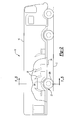
- Figure 1 schematically illustrates a cross-sectional view of a vehicle 10 which includes a passenger compartment 12 defined by a roof 14, two side walls 16, and a vehicle floor 18.
- the cross-sectional view is taken transverse to the vehicle length. That is, substantially across the vehicle width ( Figure 2).
- the vehicle 10 includes a multiple of passenger seats 20 mounted adjacent to each of the side walls 16 with a center aisle 22 extending along the length of the vehicle 10 and between the seats 20.
- the floor 18 defined beneath the passenger seats 20 and the aisle 22 preferably defines a first profile segment 23.
- the second profile segment 24 defines the width of the aisle 22 in the axle zone while the third profile segment 26 defines the top of the wheel box.
- the profile segments 18, 24, 26 define the underside 28 of the vehicle 10.
- a first and second set of vehicle wheels 30A, 30B are each mounted to a swing-arm suspension system 32A, 32B adjacent the vehicle underside 28. It should be understood that vehicle 10 is typically provided with additional axles, driven and/or non-drive axles, and several sets of wheels including (Figure 2) multiple pairs of wheels per axle.
- a hub assembly 34A, 34B supports each respective set of wheels 30A, 30B upon a swing arm 36A, 36B.
- Each hub assembly 34A, 34B defines a rotational axis H about which the vehicle wheels 30A, 30B are rotated.
- the hub assemblies 34A, 34B are each attached to an independent swing-arm 36A, 36B which pivots about a pivot axis P.
- the swing-arm suspension systems 32A, 32B provide semi-independent articulation of each hub assembly 34A, 34B.
- the pivot axis P is located below (closer to the ground) than the rotational axis H. As the pivot point P is low to the ground, an extremely low vehicle floor 18 results.
- the rotational axis H is defined herein at a particular static condition.
- this static condition such as when the vehicle 10 is parked or traveling over level terrain, the rotational axis H of both hub assemblies 34A, 34B are substantially aligned along the rotational axis H.
- the rotational axis H of the hub assemblies may be individually displaced from the rotational axis H.
- each hub assembly 34A, 34B defines its own rotational axis H when in an articulated condition.
- Each swing-arm 36A, 36B is pivotally mounted at one end between the first and second profile segments 23, 24 at a mount 37 which defines the pivot axis P.
- An opposite end of the swing end is preferably resiliently mounted to the third profile segment 26 though a damper 43 such as a spring, an air spring, airbag or the like.
- a hub gear box 38A, 38B is operably connected to each hub assembly 34A, 34B to provide torque to drive their respective set of wheels 30A, 30B.
- An input gear box 40 drives the hub gear box 38A through a half-shaft 39 or the like.
- the input gear box 40 and hub gear box 38A are preferably mounted in a common housing 41( Figures 1,3).
- the input gear box 40A, 40B define an input axis I offset from the rotational axis H.
- the input axis I is preferably between the rotational axis H and the pivot axis P.
- the input gear box 40 includes a reduction gear set for reducing a rotational input such as preferably a spiral/bevel gear reduction box.
- the input gear box 40 alternatively or additionally includes a differential.
- the gear boxes include any type of gears known in the art, and can be configured for various reduction gear ratios as is known in the art. Appropriate gear reductions depending upon the drive source is well within the knowledge of one skilled in the art.
- a coupling 42 extends from the input gear box 40 to receive an input driveline 44 from a drive source such as vehicle engine (illustrated schematically).
- the coupling 42 of the input driveline 44 is preferably located proximate the pivot axis P to minimize relative movement during articulation of the swing arm 36.
- the input driveline 44 includes a jointed connections (illustrated schematically at 45) such as universal joints, slip shafts, constant velocity joints or the like to accommodate the relatively small movement of the input gear box 40. That is, as the pivot axis P is closest to coupling 42 ( Figure 4), motion of the input gear box coupling 40A, 40B is less than that of the hub gear box 38A, 38B hub assemblies 34A, 34B during articulation. A shallow suspension system is thereby provided which results in further lowering of the vehicle floor without sacrificing ride comfort.
- An axle housing 46 extends between the input gear box 40A and input gear box 40B.
- the axle housing 46 supports a drive shaft 48 to transmit power from the input gear box 40 to the opposite hub gear box 38B. That is, input gear box 40 receives power from the drive source and distributes it to the hub gear box 38A to drive the first hub assembly 34A. The input gear box 40 further distributes the power to the opposite hub gear box 38B through the driveshaft 48.
- the hub gear box 38B drives the hub assembly 34B.
- the axle housing 46 closely supports the drive shaft 48 to protect the rotating drive shaft 48 while providing torsional stiffness between the suspension systems 32A, 32B. Independent structural members between the wheel hub assemblies are thereby minimized.
- the axle housing 46 further serves as a torsion bar between the suspension systems 32A, 32B.
- the drive shaft 48 accommodates the semi-independent motion between the suspension systems 32A, 32B through jointed connections (illustrated schematically at 50) such as universal joints, slip shafts, constant velocity joints or the like.
Landscapes
- Engineering & Computer Science (AREA)
- Mechanical Engineering (AREA)
- Chemical & Material Sciences (AREA)
- Combustion & Propulsion (AREA)
- Transportation (AREA)
- Vehicle Body Suspensions (AREA)
Applications Claiming Priority (2)
| Application Number | Priority Date | Filing Date | Title |
|---|---|---|---|
| US98954 | 2002-03-15 | ||
| US10/098,954 US6793035B2 (en) | 2002-03-15 | 2002-03-15 | Semi-independent swing arm suspension system for a low floor vehicle |
Publications (3)
| Publication Number | Publication Date |
|---|---|
| EP1344661A2 true EP1344661A2 (fr) | 2003-09-17 |
| EP1344661A3 EP1344661A3 (fr) | 2004-09-22 |
| EP1344661B1 EP1344661B1 (fr) | 2008-06-25 |
Family
ID=27765437
Family Applications (1)
| Application Number | Title | Priority Date | Filing Date |
|---|---|---|---|
| EP03251368A Expired - Lifetime EP1344661B1 (fr) | 2002-03-15 | 2003-03-06 | Système de suspension pour un véhicule à plancher bas |
Country Status (3)
| Country | Link |
|---|---|
| US (1) | US6793035B2 (fr) |
| EP (1) | EP1344661B1 (fr) |
| DE (1) | DE60321737D1 (fr) |
Families Citing this family (14)
| Publication number | Priority date | Publication date | Assignee | Title |
|---|---|---|---|---|
| US20060237242A1 (en) * | 2000-09-25 | 2006-10-26 | Burke Robert J | Lightweight surface vehicle |
| US20040231910A1 (en) * | 2003-02-05 | 2004-11-25 | Daniel Mercier | Vehicle with articulated drive sprocket |
| HUP0300947A2 (en) * | 2003-04-10 | 2006-12-28 | Raba Futomue Kft | Portal running gear for low level floor vehicles |
| DE60322271D1 (de) * | 2003-05-02 | 2008-08-28 | Arvinmeritor Technology Llc | Invertierte portalachsenanordnung für ein fahrzeug mit niedriger flurhöhe |
| US7048087B2 (en) * | 2003-08-26 | 2006-05-23 | Arvinmeritor Technology, Llc | External shaft low floor drive axle assembly |
| US20080203718A1 (en) * | 2005-06-22 | 2008-08-28 | Mack Trucks, Inc. | Vehicle with Components Arranged Relative to Chassis Frame |
| US8528920B2 (en) | 2011-03-01 | 2013-09-10 | Arvinmeritor Technology, Llc | Adjustment assembly |
| GB201103695D0 (en) * | 2011-03-03 | 2011-04-20 | Dennis Eagle Ltd | Improvements in heavy goods vehicles |
| CN102616087A (zh) * | 2012-04-09 | 2012-08-01 | 湖北三环车桥有限公司 | 一种低入口客车前桥总成 |
| CN103693061B (zh) * | 2014-01-09 | 2016-05-25 | 沈阳新阳光机电科技有限公司 | 低地板轨道车辆转向架空气弹簧悬挂机构 |
| CN112218766B (zh) * | 2018-05-10 | 2025-01-03 | 艾里逊变速箱公司 | 用于低底盘车辆的车桥组件 |
| US11220149B2 (en) * | 2019-03-13 | 2022-01-11 | Zf Friedrichshafen Ag | Rear axle assembly designed to fit within rear axle envelope |
| IT202000006940A1 (it) * | 2020-04-02 | 2021-10-02 | Brist Axle Systems S R L | Sospensione indipendente |
| CN115214355B (zh) * | 2022-07-25 | 2022-12-13 | 中国科学院宁波材料技术与工程研究所 | 动力脚轮及移动平台 |
Family Cites Families (9)
| Publication number | Priority date | Publication date | Assignee | Title |
|---|---|---|---|---|
| US1872013A (en) * | 1929-11-09 | 1932-08-16 | Yellow Truck & Coach Mfg Co | Six wheel vehicle |
| FR1115964A (fr) * | 1953-11-14 | 1956-05-02 | Daimler Benz Ag | Dispositif de suspension d'essieu avec demi-essieux pendulaires |
| FR1096872A (fr) * | 1953-11-24 | 1955-06-27 | Mft Fr Pneumatiques Michelin | Suspension de véhicule réagissant aux efforts horizontaux |
| US3862667A (en) * | 1972-09-28 | 1975-01-28 | Eaton Corp | Drop center drive steer axle |
| US3976154A (en) * | 1975-01-13 | 1976-08-24 | Caterpillar Tractor Co. | Drive line differential apparatus for a vehicle |
| IT1238922B (it) * | 1990-05-07 | 1993-09-07 | Menarini S P A | Sistema di trazione per un autobus particolarmente per traffico locale |
| FR2682326B1 (fr) * | 1991-10-15 | 1995-06-23 | Peugeot | Suspension notamment a bras tire pour vehicule automobile, avec systeme d'amortissement des chocs longitudinaux. |
| HU9203746D0 (en) | 1992-11-27 | 1993-03-29 | Magyar Vagon Es Gepgyar | Portal type undercarriage with suspension integrated onto housing of drive |
| DE10057090A1 (de) * | 2000-11-17 | 2002-05-23 | Zahnradfabrik Friedrichshafen | Portalachse |
-
2002
- 2002-03-15 US US10/098,954 patent/US6793035B2/en not_active Expired - Fee Related
-
2003
- 2003-03-06 DE DE60321737T patent/DE60321737D1/de not_active Expired - Lifetime
- 2003-03-06 EP EP03251368A patent/EP1344661B1/fr not_active Expired - Lifetime
Non-Patent Citations (1)
| Title |
|---|
| None |
Also Published As
| Publication number | Publication date |
|---|---|
| US6793035B2 (en) | 2004-09-21 |
| US20030173137A1 (en) | 2003-09-18 |
| EP1344661A3 (fr) | 2004-09-22 |
| DE60321737D1 (de) | 2008-08-07 |
| EP1344661B1 (fr) | 2008-06-25 |
Similar Documents
| Publication | Publication Date | Title |
|---|---|---|
| US6431298B1 (en) | Drive unit assembly for an electrically driven vehicle | |
| US6793035B2 (en) | Semi-independent swing arm suspension system for a low floor vehicle | |
| US7083015B2 (en) | Low floor drive unit assembly for an electrically driven vehicle | |
| US6904988B2 (en) | Suspended wheel end powered through trailing arm | |
| US7568546B2 (en) | Low load floor motor vehicle | |
| EP0961705B1 (fr) | Ensemble unite de transmission a faible garde au sol pour vehicule electrique | |
| US20030010561A1 (en) | Low load floor motor vehicle | |
| EP0931684A1 (fr) | Véhicule, en particulier véhicule à propulsion électrique | |
| US6193007B1 (en) | Rear suspension and drive axle assembly | |
| EP4105050B1 (fr) | Système d'essieu d'entraînement | |
| EP1253038B1 (fr) | Système de suspension indépendante | |
| US6808033B2 (en) | Vehicle suspension system | |
| EP1348587A2 (fr) | Système de suspension pour un véhicule à plancher rabaissé | |
| JPH054275B2 (fr) | ||
| JPS5830878A (ja) | 車輛 | |
| US6659217B2 (en) | Drive assembly for low floor vehicle | |
| US12065034B2 (en) | Rear portal gear assembly for trailing arms | |
| EP4527654A1 (fr) | Ensemble essieu moteur électrique et véhicule comprenant l'ensemble essieu moteur électrique | |
| US11872882B2 (en) | Tri-drive transmission for rear mid-engine vehicle | |
| JPH0112985Y2 (fr) | ||
| KR20260011486A (ko) | 차량용 구동장치 | |
| JPS6157427A (ja) | ミツドシツプ型車両 | |
| KR19980049107A (ko) | 자동차의 액슬축 연결장치 |
Legal Events
| Date | Code | Title | Description |
|---|---|---|---|
| PUAI | Public reference made under article 153(3) epc to a published international application that has entered the european phase |
Free format text: ORIGINAL CODE: 0009012 |
|
| AK | Designated contracting states |
Kind code of ref document: A2 Designated state(s): AT BE BG CH CY CZ DE DK EE ES FI FR GB GR HU IE IT LI LU MC NL PT RO SE SI SK TR |
|
| AX | Request for extension of the european patent |
Extension state: AL LT LV MK |
|
| PUAL | Search report despatched |
Free format text: ORIGINAL CODE: 0009013 |
|
| AK | Designated contracting states |
Kind code of ref document: A3 Designated state(s): AT BE BG CH CY CZ DE DK EE ES FI FR GB GR HU IE IT LI LU MC NL PT RO SE SI SK TR |
|
| AX | Request for extension of the european patent |
Extension state: AL LT LV MK |
|
| 17P | Request for examination filed |
Effective date: 20041025 |
|
| 17Q | First examination report despatched |
Effective date: 20050203 |
|
| AKX | Designation fees paid |
Designated state(s): DE FR GB IT |
|
| 17Q | First examination report despatched |
Effective date: 20050203 |
|
| GRAP | Despatch of communication of intention to grant a patent |
Free format text: ORIGINAL CODE: EPIDOSNIGR1 |
|
| GRAS | Grant fee paid |
Free format text: ORIGINAL CODE: EPIDOSNIGR3 |
|
| GRAA | (expected) grant |
Free format text: ORIGINAL CODE: 0009210 |
|
| AK | Designated contracting states |
Kind code of ref document: B1 Designated state(s): DE FR GB IT |
|
| REG | Reference to a national code |
Ref country code: GB Ref legal event code: FG4D |
|
| REF | Corresponds to: |
Ref document number: 60321737 Country of ref document: DE Date of ref document: 20080807 Kind code of ref document: P |
|
| PLBE | No opposition filed within time limit |
Free format text: ORIGINAL CODE: 0009261 |
|
| STAA | Information on the status of an ep patent application or granted ep patent |
Free format text: STATUS: NO OPPOSITION FILED WITHIN TIME LIMIT |
|
| 26N | No opposition filed |
Effective date: 20090326 |
|
| PG25 | Lapsed in a contracting state [announced via postgrant information from national office to epo] |
Ref country code: IT Free format text: LAPSE BECAUSE OF NON-PAYMENT OF DUE FEES Effective date: 20090306 |
|
| PGFP | Annual fee paid to national office [announced via postgrant information from national office to epo] |
Ref country code: FR Payment date: 20110317 Year of fee payment: 9 |
|
| PGFP | Annual fee paid to national office [announced via postgrant information from national office to epo] |
Ref country code: GB Payment date: 20110302 Year of fee payment: 9 Ref country code: IT Payment date: 20110315 Year of fee payment: 9 Ref country code: DE Payment date: 20110302 Year of fee payment: 9 |
|
| PGRI | Patent reinstated in contracting state [announced from national office to epo] |
Ref country code: IT Effective date: 20110616 |
|
| GBPC | Gb: european patent ceased through non-payment of renewal fee |
Effective date: 20120306 |
|
| REG | Reference to a national code |
Ref country code: FR Ref legal event code: ST Effective date: 20121130 |
|
| PG25 | Lapsed in a contracting state [announced via postgrant information from national office to epo] |
Ref country code: FR Free format text: LAPSE BECAUSE OF NON-PAYMENT OF DUE FEES Effective date: 20120402 Ref country code: GB Free format text: LAPSE BECAUSE OF NON-PAYMENT OF DUE FEES Effective date: 20120306 |
|
| REG | Reference to a national code |
Ref country code: DE Ref legal event code: R119 Ref document number: 60321737 Country of ref document: DE Effective date: 20121002 |
|
| PG25 | Lapsed in a contracting state [announced via postgrant information from national office to epo] |
Ref country code: IT Free format text: LAPSE BECAUSE OF NON-PAYMENT OF DUE FEES Effective date: 20120306 |
|
| PG25 | Lapsed in a contracting state [announced via postgrant information from national office to epo] |
Ref country code: DE Free format text: LAPSE BECAUSE OF NON-PAYMENT OF DUE FEES Effective date: 20121002 |