EP1344914B1 - Moteur à combustion interne avec dispositif d'injection de carburant - Google Patents
Moteur à combustion interne avec dispositif d'injection de carburant Download PDFInfo
- Publication number
- EP1344914B1 EP1344914B1 EP03290497A EP03290497A EP1344914B1 EP 1344914 B1 EP1344914 B1 EP 1344914B1 EP 03290497 A EP03290497 A EP 03290497A EP 03290497 A EP03290497 A EP 03290497A EP 1344914 B1 EP1344914 B1 EP 1344914B1
- Authority
- EP
- European Patent Office
- Prior art keywords
- angle
- fuel
- jets
- cylinder
- bowl
- Prior art date
- Legal status (The legal status is an assumption and is not a legal conclusion. Google has not performed a legal analysis and makes no representation as to the accuracy of the status listed.)
- Expired - Lifetime
Links
Images

Classifications
-
- F—MECHANICAL ENGINEERING; LIGHTING; HEATING; WEAPONS; BLASTING
- F02—COMBUSTION ENGINES; HOT-GAS OR COMBUSTION-PRODUCT ENGINE PLANTS
- F02M—SUPPLYING COMBUSTION ENGINES IN GENERAL WITH COMBUSTIBLE MIXTURES OR CONSTITUENTS THEREOF
- F02M61/00—Fuel-injectors not provided for in groups F02M39/00 - F02M57/00 or F02M67/00
- F02M61/16—Details not provided for in, or of interest apart from, the apparatus of groups F02M61/02 - F02M61/14
- F02M61/18—Injection nozzles, e.g. having valve seats; Details of valve member seated ends, not otherwise provided for
- F02M61/1806—Injection nozzles, e.g. having valve seats; Details of valve member seated ends, not otherwise provided for characterised by the arrangement of discharge orifices, e.g. orientation or size
-
- F—MECHANICAL ENGINEERING; LIGHTING; HEATING; WEAPONS; BLASTING
- F02—COMBUSTION ENGINES; HOT-GAS OR COMBUSTION-PRODUCT ENGINE PLANTS
- F02B—INTERNAL-COMBUSTION PISTON ENGINES; COMBUSTION ENGINES IN GENERAL
- F02B23/00—Other engines characterised by special shape or construction of combustion chambers to improve operation
- F02B23/02—Other engines characterised by special shape or construction of combustion chambers to improve operation with compression ignition
- F02B23/06—Other engines characterised by special shape or construction of combustion chambers to improve operation with compression ignition the combustion space being arranged in working piston
-
- F—MECHANICAL ENGINEERING; LIGHTING; HEATING; WEAPONS; BLASTING
- F02—COMBUSTION ENGINES; HOT-GAS OR COMBUSTION-PRODUCT ENGINE PLANTS
- F02B—INTERNAL-COMBUSTION PISTON ENGINES; COMBUSTION ENGINES IN GENERAL
- F02B1/00—Engines characterised by fuel-air mixture compression
- F02B1/12—Engines characterised by fuel-air mixture compression with compression ignition
-
- F—MECHANICAL ENGINEERING; LIGHTING; HEATING; WEAPONS; BLASTING
- F02—COMBUSTION ENGINES; HOT-GAS OR COMBUSTION-PRODUCT ENGINE PLANTS
- F02B—INTERNAL-COMBUSTION PISTON ENGINES; COMBUSTION ENGINES IN GENERAL
- F02B23/00—Other engines characterised by special shape or construction of combustion chambers to improve operation
- F02B23/02—Other engines characterised by special shape or construction of combustion chambers to improve operation with compression ignition
- F02B23/06—Other engines characterised by special shape or construction of combustion chambers to improve operation with compression ignition the combustion space being arranged in working piston
- F02B23/0645—Details related to the fuel injector or the fuel spray
- F02B23/0648—Means or methods to improve the spray dispersion, evaporation or ignition
- F02B23/0651—Means or methods to improve the spray dispersion, evaporation or ignition the fuel spray impinging on reflecting surfaces or being specially guided throughout the combustion space
-
- F—MECHANICAL ENGINEERING; LIGHTING; HEATING; WEAPONS; BLASTING
- F02—COMBUSTION ENGINES; HOT-GAS OR COMBUSTION-PRODUCT ENGINE PLANTS
- F02B—INTERNAL-COMBUSTION PISTON ENGINES; COMBUSTION ENGINES IN GENERAL
- F02B23/00—Other engines characterised by special shape or construction of combustion chambers to improve operation
- F02B23/02—Other engines characterised by special shape or construction of combustion chambers to improve operation with compression ignition
- F02B23/06—Other engines characterised by special shape or construction of combustion chambers to improve operation with compression ignition the combustion space being arranged in working piston
- F02B23/0696—W-piston bowl, i.e. the combustion space having a central projection pointing towards the cylinder head and the surrounding wall being inclined towards the cylinder wall
-
- F—MECHANICAL ENGINEERING; LIGHTING; HEATING; WEAPONS; BLASTING
- F02—COMBUSTION ENGINES; HOT-GAS OR COMBUSTION-PRODUCT ENGINE PLANTS
- F02B—INTERNAL-COMBUSTION PISTON ENGINES; COMBUSTION ENGINES IN GENERAL
- F02B31/00—Modifying induction systems for imparting a rotation to the charge in the cylinder
-
- F—MECHANICAL ENGINEERING; LIGHTING; HEATING; WEAPONS; BLASTING
- F02—COMBUSTION ENGINES; HOT-GAS OR COMBUSTION-PRODUCT ENGINE PLANTS
- F02B—INTERNAL-COMBUSTION PISTON ENGINES; COMBUSTION ENGINES IN GENERAL
- F02B2275/00—Other engines, components or details, not provided for in other groups of this subclass
- F02B2275/14—Direct injection into combustion chamber
-
- F—MECHANICAL ENGINEERING; LIGHTING; HEATING; WEAPONS; BLASTING
- F02—COMBUSTION ENGINES; HOT-GAS OR COMBUSTION-PRODUCT ENGINE PLANTS
- F02B—INTERNAL-COMBUSTION PISTON ENGINES; COMBUSTION ENGINES IN GENERAL
- F02B23/00—Other engines characterised by special shape or construction of combustion chambers to improve operation
- F02B23/02—Other engines characterised by special shape or construction of combustion chambers to improve operation with compression ignition
- F02B23/06—Other engines characterised by special shape or construction of combustion chambers to improve operation with compression ignition the combustion space being arranged in working piston
- F02B23/0645—Details related to the fuel injector or the fuel spray
- F02B23/0669—Details related to the fuel injector or the fuel spray having multiple fuel spray jets per injector nozzle
-
- F—MECHANICAL ENGINEERING; LIGHTING; HEATING; WEAPONS; BLASTING
- F02—COMBUSTION ENGINES; HOT-GAS OR COMBUSTION-PRODUCT ENGINE PLANTS
- F02B—INTERNAL-COMBUSTION PISTON ENGINES; COMBUSTION ENGINES IN GENERAL
- F02B3/00—Engines characterised by air compression and subsequent fuel addition
- F02B3/06—Engines characterised by air compression and subsequent fuel addition with compression ignition
-
- F—MECHANICAL ENGINEERING; LIGHTING; HEATING; WEAPONS; BLASTING
- F02—COMBUSTION ENGINES; HOT-GAS OR COMBUSTION-PRODUCT ENGINE PLANTS
- F02F—CYLINDERS, PISTONS OR CASINGS, FOR COMBUSTION ENGINES; ARRANGEMENTS OF SEALINGS IN COMBUSTION ENGINES
- F02F1/00—Cylinders; Cylinder heads
- F02F1/24—Cylinder heads
- F02F2001/244—Arrangement of valve stems in cylinder heads
- F02F2001/247—Arrangement of valve stems in cylinder heads the valve stems being orientated in parallel with the cylinder axis
-
- F—MECHANICAL ENGINEERING; LIGHTING; HEATING; WEAPONS; BLASTING
- F02—COMBUSTION ENGINES; HOT-GAS OR COMBUSTION-PRODUCT ENGINE PLANTS
- F02F—CYLINDERS, PISTONS OR CASINGS, FOR COMBUSTION ENGINES; ARRANGEMENTS OF SEALINGS IN COMBUSTION ENGINES
- F02F3/00—Pistons
- F02F3/26—Pistons having combustion chamber in piston head
-
- Y—GENERAL TAGGING OF NEW TECHNOLOGICAL DEVELOPMENTS; GENERAL TAGGING OF CROSS-SECTIONAL TECHNOLOGIES SPANNING OVER SEVERAL SECTIONS OF THE IPC; TECHNICAL SUBJECTS COVERED BY FORMER USPC CROSS-REFERENCE ART COLLECTIONS [XRACs] AND DIGESTS
- Y02—TECHNOLOGIES OR APPLICATIONS FOR MITIGATION OR ADAPTATION AGAINST CLIMATE CHANGE
- Y02T—CLIMATE CHANGE MITIGATION TECHNOLOGIES RELATED TO TRANSPORTATION
- Y02T10/00—Road transport of goods or passengers
- Y02T10/10—Internal combustion engine [ICE] based vehicles
- Y02T10/12—Improving ICE efficiencies
Definitions
- the present invention relates to an internal combustion engine with a direct fuel injection device.
- a direct injection internal combustion engine comprising at least one cylinder, a cylinder head, a piston sliding in this cylinder, means for admitting at least one gaseous fluid, a multi jet fuel injector comprising a fuel jet angle and a fuel jet ply angle, and a combustion chamber defined on one side by the upper face of the piston comprising a pin protruding towards the cylinder head and disposed in a concave bowl, as described in FIG. as an example in the document DE 1 055 873 .
- the present invention proposes to overcome the drawbacks mentioned above by means of a simple and economical design engine. It is a motor that can operate in two modes of combustion, switching from one mode to another is mainly by changing the phasing injections.
- the geometry retained by the jets is based on the use of a low-angle injector associated with a particular number of jets to, firstly, ensure a sufficiently homogeneous mixture of the fuel with the admitted gaseous fluid (s) (air or air and recirculated exhaust gas) while avoiding the wetting of the cylinder wall by the fuel in homogeneous combustion mode and, secondly, ensure a good independence of each fuel jet in traditional combustion.
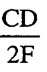
- the invention relates to a direct injection internal combustion engine comprising at least one cylinder, a cylinder head, a piston sliding in this cylinder, admission means for at least one gaseous fluid, a multi fuel injector jets comprising an angle of fuel jets between the consecutive axes of said jets and a fuel jet ply angle, and a combustion chamber delimited on one side by the upper face of the piston, said face comprising a stud pointing towards the cylinder head; being arranged in a concave bowl, characterized in that the angle of fuel jets is at least equal to 10 ⁇ ⁇ FD where FD is the bottom diameter of the bowl and that the tableclean angle is less than or equal to CD 2 ⁇ F where CD is the diameter of the cylinder and F is the distance between the point of origin of the fuel jets and the position of the piston corresponding to a crankshaft angle of 50 ° with respect to the top dead center.
- the angle of ply of fuel jets may be less than or equal to 120 °.
- the lap angle may be between 40 ° and 100 °.
- the angle at the apex of the nipple may be chosen greater than the angle of coverage of a value between 0 ° and 30 °.
- the axes of the fuel jets can form with the flank of the nipple an angle of intersection of the order of 5 °.
- a direct injection internal combustion engine of the Diesel type comprises at least one cylinder 10 of axis XX 'and of diameter CD, a cylinder head 12, at least one intake manifold 14 of at least one gaseous fluid, such as air or a mixture of air and recirculated gas (EGR), at least one exhaust pipe 16, the pipes being controlled in opening, or closing, by a closure means, such as respectively an intake valve 18 and an exhaust valve 20, a piston 22 sliding in the cylinder 10 and a fuel injector 24.
- a closure means such as respectively an intake valve 18 and an exhaust valve 20
- a piston 22 sliding in the cylinder 10 and a fuel injector 24.
- the fuel injector which is preferably disposed in the axis XX 'of the cylinder, comprises in the vicinity of its nose 26 a plurality of orifices or holes 28 through which is sprayed, in the combustion chamber, the fuel according to jets 30 whose general axis is symbolized by the center line 32.
- the fuel injector is of the type with a low angle of coverage of 1 and is chosen so that the wall of the cylinder 10 is never wetted by the fuel for any position of the piston between + 50 ° and + ⁇ or between -50 ° and - ⁇ , where ⁇ represents the angle of the crankshaft for the selected injection phase relative to the top dead center (TDC), this angle ⁇ being greater than 50 ° and less than or equal to 180 ° to obtain a combustion type homogeneous.
- CD denotes the diameter (in mm) of the cylinder 10 and F the distance (in mm) between the point of origin of the fuel jets 30 and the position of the piston corresponding to a crankshaft angle of 50 °, then the angle of tablecloth at 1 (in degree) will be less than or equal to 2 Arctg CD 2 ⁇ F .
- a typical angular range for the lap angle a 1 is at most 120 ° and preferably between 40 ° and 100 °.
- the combustion chamber is delimited by the internal face of the yoke 12, the circular wall of the cylinder 10 and the upper face of the piston 22.
- This upper face of the piston comprises a concave bowl 34 inside which is disposed a pin 36 which rises towards the cylinder head 12 in the center of this bowl.
- the general axis of the bowl 34, the axis of the injector 24 and the axis of the stud 36 coincide with the axis XX 'of the cylinder, but, of course, it can be provided that the bolus, injector and nipple axes are not coaxial with that of the cylinder but the essential lies in the arrangement according to which the general axis of the ply of fuel jets, the axis of the stud and the axis of the bowl are coaxial.
- the stud 36 of generally frustoconical shape, has a vertex, preferably rounded, continuing, towards the bottom 38 of the bowl, by an inclined flank 40 that is substantially rectilinear and then, from the bottom of the bowl 38, by an inclined lateral wall 42 substantially rectilinear joining a substantially horizontal surface 44 of the upper face of the piston 22.
- the bottom of the bowl 38 consists of a substantially flat annular surface delimited, in section, by the points A and B and the diameter FD of this bottom is assessed at the average diameter of this surface, that is to say at the point level M middle of segment AB.
- the diameter FD of the bottom of the bowl will be raised at the lowest point of this concave surface, that is to say at the level of the point. further away from breech 12.
- the angle at the apex of the stud 36 and the angle of inclination of the side wall 42 of the bowl 34 are adapted substantially to the fuel jet ply angle 30, so that the fuel is injected substantially along the flank 40 of the nipple and then goes up along the side wall 42 of the bowl.
- An angle at the top of the stud is chosen in such a way that it is greater than the ply angle a 1 of the fuel jets having a value between 0 ° and 30 ° and an angle of inclination of the wall side 42 of the bowl 34 which is less than 45 °.
- nappe angle it is understood the vertex angle that forms the cone from the injector and whose imaginary peripheral wall passes through all the axes of the fuel jets.
- the axes 32 of the jets 30 form with the flank 40 of the stud 36 an angle of intersection of the order of 5 °.
- the applicant has determined, by calculation, the ideal angular difference ⁇ between two axes 32 of consecutive fuel jets 30 to obtain, on the one hand, the satisfactory operation of the engine in conventional combustion mode and, on the other hand, to ensure a homogeneous mixture of the fuel with the gaseous fluid, such as air or a mixture of air and recirculated exhaust gas (EGR).
- This angular difference is to be considered in a plane orthogonal to the axis XX '(see figure 2 ).
- the Applicant also determined an ideal bowl which included a FD bowl diameter. From this, the minimum angle ⁇ (in radian) between the consecutive axes of jets was therefore 10 ⁇ ⁇ FD (with FD in mm).
- the joint use of the relatively low angle injector 1 and an injector with a real number of holes, as defined above, allows a conventional combustion mode for a fuel injection near the top dead center ( TDC) while improving the mixing of the fuel with the gaseous fluid and avoiding the overlap of the jets between them.
- TDC top dead center
- this configuration makes it possible to avoid the presence of liquid fuel on the wall of the cylinder while offering wide possibilities of pollution control and engine performance, especially in homogeneous combustion mode.
- the engine allows a good drive vaporized fuel thus promoting its mixing with the gaseous fluid to obtain a good burn rate and high operating wealth, reflecting a good use of the gaseous fluid admitted.
- a reduced lap angle combined with the injector, as described above, avoids wetting the cylinder wall and mixing the fuel with the gaseous fluid.
Landscapes
- Engineering & Computer Science (AREA)
- Chemical & Material Sciences (AREA)
- Combustion & Propulsion (AREA)
- Mechanical Engineering (AREA)
- General Engineering & Computer Science (AREA)
- Dispersion Chemistry (AREA)
- Combustion Methods Of Internal-Combustion Engines (AREA)
- Fuel-Injection Apparatus (AREA)
Description
- La présente invention se rapporte à un moteur à combustion interne avec un dispositif d'injection directe de carburant.
- Elle se rapporte plus particulièrement à un moteur à combustion interne à injection directe comprenant au moins un cylindre, une culasse, un piston coulissant dans ce cylindre, des moyens d'admission d'au moins un fluide gazeux, un injecteur de carburant multi jets comportant un angle de jets de carburant et un angle de nappe de jets de carburant, et une chambre de combustion délimitée sur un côté par la face supérieure du piston comprenant un téton s'érigeant vers la culasse et disposé dans un bol concave, comme décrit à titre d'exemple dans le document
DE 1 055 873 . - Dans le cas de moteurs Diesel fonctionnant en mode homogène, il est connu de mélanger le carburant issu d'un injecteur multi jets avec le ou les fluides gazeux admis dans la chambre de combustion de ce moteur, tel que de l'air ou un mélange d'air et de gaz d'échappement recirculé (EGR), de manière à obtenir un mélange carburé homogène avant le démarrage de la combustion.
Cette homogénéité du mélange carburé permet de réduire la consommation et de minimiser la production d'oxydes d'azote (NOx) et de particules, tel que cela est mieux décrit dans l'article scientifique de STOMMEL P et DURNHOLZ M intitulé : "Grundlagenuntersuchung zur Gemischbildung im hochaufgeladenen, direckteinspritzenden Dieselmotor" et publié dans MTZ, vol 55, no11, page 644 à 646, 1er novembre 1994. - Pour favoriser le mélange du carburant avec le fluide gazeux admis dans la chambre de combustion, il a été mis au point des moteurs comprenant des injecteurs avec un grand nombre de trous, de l'ordre de 20 trous.
Ce type d'injecteur permet d'améliorer le fonctionnement du moteur en combustion homogène mais entraîne un mouillage de la paroi du cylindre par les gouttelettes du carburant, notamment lorsque l'aérodynamique interne de la chambre de combustion utilise un mouvement tourbillonnaire, ou swirl, du fluide gazeux admis qui projette ces gouttelettes sur cette paroi.
Ce mouillage de la paroi par le carburant entraîne, non seulement une dégradation de la tenue du lubrifiant présent sur cette paroi ainsi que la création de suies, mais aussi une augmentation des émissions de polluants et une réduction des performances du moteur, notamment en augmentant sa consommation de carburant. - Dans le cas où ce moteur fonctionne en combustion traditionnelle, notamment à forte charge de manière à atteindre un fort couple et une forte puissance spécifique, un tel nombre de jets n'est pas compatible avec ce mode de combustion.
En effet, lorsque les axes des jets de carburant sont trop proches circonférentiellement les uns des autres, les extrémités de ces jets se chevauchent les uns aux autres dans le bol, en empêchant de réaliser le mélange avec le fluide gazeux et en créant des zones trop riches en carburant, ce qui entraîne la formation de suies. - La présente invention se propose de remédier aux inconvénients mentionnés ci-dessus grâce à un moteur de conception simple et économique.
Il s'agit d'un moteur pouvant fonctionner selon deux modes de combustion, le passage d'un mode à un autre se faisant principalement par modification du phasage des injections.
La géométrie retenue des jets repose sur l'utilisation d'un injecteur à faible angle de nappe associé à un nombre particulier de jets pour, d'une part, assurer un mélange suffisamment homogène du carburant avec le ou les fluides gazeux admis (air ou air et gaz d'échappement recirculés) tout en évitant le mouillage de la paroi du cylindre par le carburant en mode de combustion homogène et, d'autre part, assurer une bonne indépendance de chaque jet de carburant en combustion traditionnelle. - A cet effet, l'invention concerne un moteur à combustion interne à injection directe comprenant au moins un cylindre, une culasse, un piston coulissant dans ce cylindre, des moyens d'admission d'au moins un fluide gazeux, un injecteur de carburant multi jets comportant un angle de jets de carburant entre les axes consécutifs desdits jets et un angle de nappe de jets de carburant, et une chambre de combustion délimitée sur un côté par la face supérieure du piston, ladite face comprenant un téton pointant vers la culasse en étant disposé dans un bol concave, caractérisé en ce que l'angle de jets de carburant est au moins égal à

- Préférentiellement, l'angle de nappe de jets de carburant peut être inférieur ou égal à 120°.
- Avantageusement, l'angle de nappe peut être compris entre 40° et 100°.
- L'angle au sommet du téton peut être choisi supérieur à l'angle de nappe d'une valeur comprise entre 0° et 30°.
- Les axes des jets de carburant peuvent former avec le flanc du téton un angle d'intersection de l'ordre de 5°.
- Les autres caractéristiques et avantages de l'invention apparaîtront à la lecture de la description donnée ci-après à partir d'un exemple non limitatif de réalisation et en se référant aux dessins annexés où :
- la
figure 1 montre schématiquement un moteur à combustion interne avec un injecteur de carburant selon l'invention et - la
figure 2 est une vue en coupe selon la ligne 2-2 de lafigure 1 . - En se référant aux
figures 1 et 2 , un moteur à combustion interne à injection directe, de type Diesel, comprend au moins un cylindre 10 d'axe XX' et de diamètre CD, une culasse 12, au moins une tubulure d'admission 14 d'au moins un fluide gazeux, tel que de l'air ou un mélange d'air et de gaz recirculés (EGR), au moins une tubulure d'échappement 16, les tubulures étant commandées en ouverture, ou en fermeture, par un moyen d'obturation, tel que respectivement une soupape d'admission 18 et une soupape d'échappement 20, un piston 22 coulissant dans le cylindre 10 et un injecteur de carburant 24. - L'injecteur de carburant, qui est préférentiellement disposé dans l'axe XX' du cylindre, comporte au voisinage de son nez 26 une multiplicité d'orifices ou trous 28 à travers desquels est pulvérisé, dans la chambre de combustion, le carburant selon des jets 30 dont l'axe général est symbolisé par le trait d'axe 32.
- L'injecteur de carburant est de type à faible angle de nappe a1 et est choisi pour que la paroi du cylindre 10 ne soit jamais mouillée par le carburant pour toute position du piston comprise entre + 50° et +α ou entre -50° et -α, où α représente l'angle du vilebrequin pour la phase d'injection choisie par rapport au point mort haut (PMH), cet angle α étant supérieur à 50° et inférieur ou égal à 180° pour obtenir une combustion de type homogène.
- Si CD désigne le diamètre (en mm) du cylindre 10 et F la distance (en mm) entre le point d'origine des jets de carburants 30 et la position du piston correspondant à un angle de vilebrequin de 50°, alors l'angle de nappe a1 (en degré) sera inférieur ou égal à 2Arctg

- Une fourchette angulaire typique pour l'angle de nappe a1 est au plus de 120° et préférentiellement entre 40° et 100°.
- La chambre de combustion est délimitée par la face interne de la culasse 12, la paroi circulaire du cylindre 10 et la face supérieure du piston 22.
Cette face supérieure du piston comporte un bol concave 34 à l'intérieur duquel est disposé un téton 36 qui s'élève vers la culasse 12 en se situant au centre de ce bol. - Dans l'exemple représenté, l'axe général du bol 34, l'axe de l'injecteur 24 et l'axe du téton 36 sont confondus avec l'axe XX' du cylindre mais, bien entendu, il peut être prévu que les axes du bol, de l'injecteur et du téton ne soient pas coaxiaux avec celui du cylindre mais l'essentiel réside dans la disposition selon laquelle l'axe général de la nappe de jets de carburant, l'axe du téton et l'axe du bol soient coaxiaux.
- Le téton 36, de forme générale tronconique, comporte un sommet, de préférence arrondi, se poursuivant, en direction du fond 38 du bol, par un flanc incliné 40 sensiblement rectiligne puis, à partir du fond du bol 38, par une paroi latérale inclinée 42 sensiblement rectiligne rejoignant une surface sensiblement horizontale 44 de la face supérieure du piston 22.
- Dans l'exemple de la
figure 1 , le fond du bol 38 est constitué d'une face sensiblement plane annulaire délimitée, en section, par les points A et B et le diamètre FD de ce fond s'apprécie au niveau du diamètre moyen de cette surface c'est à dire au niveau du point M milieu du segment AB.
Dans le cas où le fond de ce bol est formé par une surface concave arrondie, le diamètre FD du fond du bol sera relevé au niveau du point le plus bas de cette surface concave, c'est-à-dire au niveau du point le plus éloigné de la culasse 12. - L'angle au sommet du téton 36 et l'angle d'inclinaison de la paroi latérale 42 du bol 34 sont adaptés sensiblement à l'angle de nappe de jets de carburant 30, de façon à ce que le carburant soit injecté sensiblement le long du flanc 40 du téton puis remonte le long de la paroi latérale 42 du bol.
- On choisit un angle au sommet du téton d'une façon telle qu'il soit supérieur à l'angle de nappe a1 des jets de carburant d'une valeur comprise entre 0° et 30° et un angle d'inclinaison de la paroi latérale 42 du bol 34 qui soit inférieur à 45°.
- Par angle de nappe, il est entendu l'angle au sommet que forme le cône issu de l'injecteur et dont la paroi périphérique fictive passe par tous les axes des jets de carburant.
- Préférentiellement, il est prévu que les axes 32 des jets 30 forment avec le flanc 40 du téton 36 un angle d'intersection de l'ordre de 5°.
- Comme déjà explicité, il est nécessaire que les écarts angulaires circonférentiels des jets soient prévus de telle manière que ces jets ne se recouvrent pas les uns aux autres dans le bol.
- Pour cela, le demandeur a déterminé, par le calcul, l'écart angulaire idéal β entre deux axes 32 de jets de carburants 30 consécutifs permettant d'obtenir, d'une part, le fonctionnement satisfaisant du moteur en mode de combustion traditionnelle et, d'autre part, d'assurer un mélange homogène du carburant avec le fluide gazeux, tel que de l'air ou un mélange d'air et de gaz d'échappement recirculé (EGR). Cet écart angulaire est à considérer dans un plan orthogonal à l'axe XX' (voir
figure 2 ).
Associé à cet injecteur, le demandeur a également déterminé un bol idéal qui comportait un diamètre de fond de bol FD.
A partir de cela, l'angle β minimum (en radian) entre les axes consécutifs de jets a donc été de
- De cet angle β, il pourra être ensuite calculé le nombre Nt de trous 28 de l'injecteur 24, dit nombre calculé de trous, et par conséquent le nombre de jets 30 répartis régulièrement circonférentiellement autour de l'axe de l'injecteur.
Si Nt n'est pas un nombre entier, il sera déterminé un nombre réel de trous par valeur inférieure la plus proche d'un entier. - A titre d'exemple, si le nombre calculé de trous Nt est de 5,8, le nombre entier le plus proche de ce nombre calculé est 5 et, par conséquent, il sera utilisé un injecteur avec 5 trous.
- L'utilisation conjointe de l'injecteur à angle de nappe a1 relativement faible et d'un injecteur avec un nombre réel de trous, tel que défini précédemment, autorise un mode de combustion traditionnelle pour une injection de carburant près du point mort haut (PMH) tout en améliorant le mélange du carburant avec le fluide gazeux et en évitant le recouvrement des jets entre eux.
De plus, cette configuration permet d'éviter la présence de carburant liquide sur la paroi du cylindre tout en offrant de larges possibilités de contrôle de la pollution et des performances des moteurs, notamment en mode de combustion homogène. - A pleine charge et aux charges élevées, le moteur permet un bon entraînement du carburant vaporisé favorisant ainsi son mélange avec le fluide gazeux afin d'obtenir une bonne vitesse de combustion et des richesses de fonctionnement élevées, traduisant une bonne utilisation du fluide gazeux admis. Aux charges partielles, un angle de nappe réduit combiné à l'injecteur, comme décrit plus haut, permet d'éviter le mouillage de la paroi du cylindre et d'assurer le mélange du carburant avec le fluide gazeux.
Claims (5)
- Moteur à combustion interne à injection directe comprenant au moins un cylindre (10), une culasse (12), un piston (22) coulissant dans ce cylindre, des moyens d'admission (14, 18) d'au moins un fluide gazeux, un injecteur de carburant multi jets (24) comportant un angle de jets (β) de carburant entre les axes consécutifs desdits jets et un angle de nappe (a1) de jets de carburant, et une chambre de combustion délimitée sur un côté par la face supérieure du piston (22), ladite face comprenant un téton (36) pointant vers la culasse (12) en étant disposé dans un bol concave (34), caractérisé en ce que l'angle (β) de jets de carburant est au moins égal à


- Moteur selon la revendication 1, caractérisé en ce que l'angle de nappe (a1) de jets de carburant (30) est inférieur ou égal à 120°.
- Moteur selon la revendication 1 ou 2, caractérisé en ce que l'angle de nappe (a1) est compris entre 40° et 100°.
- Moteur selon l'une des revendications 1 à 3, caractérisé en ce que l'angle au sommet du téton (36) est choisi supérieur à l'angle de nappe (a1) d'une valeur comprise entre 0° et 30°.
- Moteur selon la revendication 1, caractérisé en ce que les axes (32) des jets de carburant (30) forment avec le flanc (40) du téton (36) un angle d'intersection de l'ordre de 5°.
Applications Claiming Priority (2)
| Application Number | Priority Date | Filing Date | Title |
|---|---|---|---|
| FR0203213 | 2002-03-15 | ||
| FR0203213A FR2837238B1 (fr) | 2002-03-15 | 2002-03-15 | Moteur a combustion interne avec dispositif d'injection de carburant |
Publications (2)
| Publication Number | Publication Date |
|---|---|
| EP1344914A1 EP1344914A1 (fr) | 2003-09-17 |
| EP1344914B1 true EP1344914B1 (fr) | 2010-05-19 |
Family
ID=27763741
Family Applications (1)
| Application Number | Title | Priority Date | Filing Date |
|---|---|---|---|
| EP03290497A Expired - Lifetime EP1344914B1 (fr) | 2002-03-15 | 2003-03-03 | Moteur à combustion interne avec dispositif d'injection de carburant |
Country Status (7)
| Country | Link |
|---|---|
| US (1) | US6675767B2 (fr) |
| EP (1) | EP1344914B1 (fr) |
| JP (1) | JP2003278549A (fr) |
| KR (1) | KR20030074406A (fr) |
| DE (1) | DE60332575D1 (fr) |
| ES (1) | ES2344196T3 (fr) |
| FR (1) | FR2837238B1 (fr) |
Families Citing this family (11)
| Publication number | Priority date | Publication date | Assignee | Title |
|---|---|---|---|---|
| DE10213025B4 (de) * | 2002-03-22 | 2014-02-27 | Daimler Ag | Selbstzündende Brennkraftmaschine |
| FR2837878B1 (fr) * | 2002-03-28 | 2004-05-28 | Inst Francais Du Petrole | Procede d'injection de carburant pour moteur a combustion interne a forte sensibilite d'injection et moteur utilisant un tel procede |
| DE10261185A1 (de) * | 2002-12-20 | 2004-07-15 | Daimlerchrysler Ag | Direkteinspritzende Otto-Brennkraftmaschine |
| DE102004002296B4 (de) * | 2004-01-16 | 2013-10-10 | Audi Ag | Kraftstoffeinspritzung und Verfahren zur Einspritzung von Kraftstoff |
| EP1605147A1 (fr) * | 2004-06-07 | 2005-12-14 | Delphi Technologies, Inc. | Dispositif pour améliorer la combustion |
| FR2879676A1 (fr) * | 2004-12-22 | 2006-06-23 | Renault Sas | Moteur a injection directe |
| FR2883336B1 (fr) * | 2005-03-17 | 2007-05-11 | Inst Francais Du Petrole | Moteur a combustion interne, notamment a injection directe, avec un piston muni d'un bol conprenant un teton |
| DE102006020642B4 (de) * | 2006-05-04 | 2019-05-23 | Daimler Ag | Verfahren zum Betrieb einer Brennkraftmaschine und Brennkraftmaschine für ein solches Verfahren |
| JP5003496B2 (ja) * | 2008-01-08 | 2012-08-15 | マツダ株式会社 | レシプロエンジン |
| FR2933449B1 (fr) * | 2008-07-03 | 2010-07-30 | Inst Francais Du Petrole | Procede pour ameliorer la vaporisation d'un carburant utlise pour un moteur a combustion interne, notamment a injection directe, en particulier a autoallumage et plus particulierement de type diesel |
| US7954471B2 (en) * | 2008-07-07 | 2011-06-07 | Mazda Motor Corporation | Spark ignited internal combustion engine and manufacturing the same |
Family Cites Families (13)
| Publication number | Priority date | Publication date | Assignee | Title |
|---|---|---|---|---|
| DE1055873B (de) * | 1955-09-07 | 1959-04-23 | Hans Krug | Luftverdichtende, selbstzuendende Brennkraftmaschine |
| JPS58501332A (ja) * | 1981-08-13 | 1983-08-11 | マツセイ−フア−ガソン−パ−キンス リミテツド | 内燃機関 |
| JPS5912120A (ja) * | 1982-07-13 | 1984-01-21 | Toyota Central Res & Dev Lab Inc | 直接噴射式内燃機関 |
| DE3325586C2 (de) * | 1983-07-15 | 1986-08-28 | Daimler-Benz Ag, 7000 Stuttgart | Brennstoffeinspritzdüse für eine luftverdichtende Brennkraftmaschine |
| SU1576697A1 (ru) * | 1988-04-18 | 1990-07-07 | Производственное Объединение "Челябинский Тракторный Завод Им.В.И.Ленина" | Двигатель внутреннего сгорани с воспламенением от сжати |
| JP2821780B2 (ja) * | 1989-11-06 | 1998-11-05 | ヤンマーディーゼル株式会社 | 直接噴射式ディーゼル機関の燃焼方法 |
| JPH05149137A (ja) * | 1991-11-22 | 1993-06-15 | Komatsu Ltd | ピストンと燃料噴射方向の設定方法 |
| JPH05288134A (ja) * | 1992-04-09 | 1993-11-02 | Sanshin Ind Co Ltd | 筒内燃料噴射式の2サイクルエンジン |
| DE4413556A1 (de) * | 1994-04-19 | 1995-11-02 | Man Nutzfahrzeuge Ag | Brennraumform für eine luftverdichtende, direkteinspritzende und selbstzündende Brennkraftmaschine mit Abgasturbolader |
| GB9605838D0 (en) * | 1996-03-20 | 1996-05-22 | Perkins Ltd | A method for producing a piston for an internal combustion engine and a piston produced by the method |
| DE19712357B4 (de) * | 1997-03-25 | 2004-05-06 | Harald Echtle | Verfahren zur Gemischbildung bei einer direkteinspritzenden Brennkraftmaschine |
| US5875743A (en) * | 1997-07-28 | 1999-03-02 | Southwest Research Institute | Apparatus and method for reducing emissions in a dual combustion mode diesel engine |
| US6536404B2 (en) * | 2001-07-23 | 2003-03-25 | International Engine Intellectual Property Company, L.L.C. | Piston having combustion chamber defined in the crown |
-
2002
- 2002-03-15 FR FR0203213A patent/FR2837238B1/fr not_active Expired - Fee Related
-
2003
- 2003-03-03 ES ES03290497T patent/ES2344196T3/es not_active Expired - Lifetime
- 2003-03-03 DE DE60332575T patent/DE60332575D1/de not_active Expired - Lifetime
- 2003-03-03 EP EP03290497A patent/EP1344914B1/fr not_active Expired - Lifetime
- 2003-03-12 US US10/385,845 patent/US6675767B2/en not_active Expired - Fee Related
- 2003-03-13 KR KR10-2003-0015606A patent/KR20030074406A/ko not_active Ceased
- 2003-03-14 JP JP2003069644A patent/JP2003278549A/ja active Pending
Also Published As
| Publication number | Publication date |
|---|---|
| US6675767B2 (en) | 2004-01-13 |
| EP1344914A1 (fr) | 2003-09-17 |
| JP2003278549A (ja) | 2003-10-02 |
| ES2344196T3 (es) | 2010-08-20 |
| FR2837238B1 (fr) | 2004-05-28 |
| DE60332575D1 (de) | 2010-07-01 |
| FR2837238A1 (fr) | 2003-09-19 |
| US20030172902A1 (en) | 2003-09-18 |
| KR20030074406A (ko) | 2003-09-19 |
Similar Documents
| Publication | Publication Date | Title |
|---|---|---|
| EP1217186B1 (fr) | Moteur à injection directe pourvu d'un faible angle de nappe et procédés permettant d'utiliser un tel moteur | |
| EP3099908B1 (fr) | Moteur à combustion à injection directe de combustible et plus particulièrement moteur à allumage par compression avec faible taux de compression | |
| EP3060774B1 (fr) | Moteur à combustion à injection directe de combustible à allumage par compression et procédé d'injection de combustible pour un tel moteur | |
| FR3019589B1 (fr) | Procede d'injection de combustible dans la chambre de combustion d'un moteur a combustion interne fonctionnant en monocarburation ou en multicarburation | |
| EP3105452B1 (fr) | Moteur à combustion interne à injection de deux nappes de combustible à débit différencié et procédé d'injection de combustible pour un tel moteur | |
| EP3134627B1 (fr) | Moteur à combustion interne à injection directe à double angle de nappe pour réaliser un mélange carburé dans une chambre de combustion à double zone de combustion et à faible taux de compression et procédé pour utiliser un tel moteur | |
| WO2017129386A1 (fr) | Moteur à combustion interne à taux de compression variable avec deux zones de mélange, notamment pour véhicule automobile et procédé d'injection pour un tel moteur | |
| EP1344914B1 (fr) | Moteur à combustion interne avec dispositif d'injection de carburant | |
| EP2261491A1 (fr) | Procédé d'injection de carburant dans un moteur à combustion interne à auto-inflammation à injection directe | |
| FR2818325A1 (fr) | Moteur a injection directe pourvu d'un faible angle de nappe et procedes permettant d'utiliser un tel moteur | |
| EP1801398B1 (fr) | Procédé d'injection de carburant pour moteur à combustion interne, notamment à injection directe, comportant un piston muni d'un bol avec un téton | |
| EP1340891B1 (fr) | Procédé et moteur pour assurer le mélange d'au moins un fluide gazeux, tel que de l'air, et d'un carburant dans la chambre de combustion d'un moteur à combustion interne à injection directe | |
| EP1348847B1 (fr) | Procédé d'injection de carburant pour moteur à combustion interne à forte sensibilité d'injection et moteur utilisant un tel procédé | |
| EP1861596B1 (fr) | Moteur a combustion interne, notamment a injection directe, avec un piston muni d'un bol comprenant un teton | |
| WO2015071093A1 (fr) | Procédé pour mélanger au moins un comburant et au moins un combustible dans la chambre de combustion d'un moteur à combustion interne à injection directe à allumage par compression et moteur utilisant un tel procédé | |
| EP1460257B1 (fr) | Moteur à combustion interne à injection directe | |
| FR2818324A1 (fr) | Moteur a injection directe, pourvu d'un injecteur a faible angle de nappe | |
| FR2878906A1 (fr) | Moteur a injection directe de carburant avec un piston comportant un bol presentant une paroi laterale inclinee | |
| WO2015058906A1 (fr) | Moteur à combustion interne à injection directe à allumage par compression et procédé d'injection de combustible dans la chambre de combustion de ce moteur | |
| FR3034137A1 (fr) | Moteur a combustion interne a injection directe de carburant a bas transfert thermique, notamment pour vehicule automobile. | |
| FR2756589A1 (fr) | Moteur a combustion interne a allumage par compression et a injection directe | |
| FR2925115A1 (fr) | Moteur a combustion interne a injection directe de carburant et procede pour realiser un melange carbure utilise pour ce moteur | |
| FR2904053A1 (fr) | Moteur a combustion interne a injection directe,en particulier de type diesel,avec un piston muni d'un bol dote d'au moins une surface deflectrice de carburant | |
| FR2910539A1 (fr) | Agencement de l'element de chauffage d'une bougie de prechauffage dans une chambre de combustion |
Legal Events
| Date | Code | Title | Description |
|---|---|---|---|
| PUAI | Public reference made under article 153(3) epc to a published international application that has entered the european phase |
Free format text: ORIGINAL CODE: 0009012 |
|
| AK | Designated contracting states |
Kind code of ref document: A1 Designated state(s): AT BE BG CH CY CZ DE DK EE ES FI FR GB GR HU IE IT LI LU MC NL PT RO SE SI SK TR |
|
| AX | Request for extension of the european patent |
Extension state: AL LT LV MK |
|
| 17P | Request for examination filed |
Effective date: 20040317 |
|
| AKX | Designation fees paid |
Designated state(s): DE ES GB IT |
|
| 17Q | First examination report despatched |
Effective date: 20040524 |
|
| GRAP | Despatch of communication of intention to grant a patent |
Free format text: ORIGINAL CODE: EPIDOSNIGR1 |
|
| GRAS | Grant fee paid |
Free format text: ORIGINAL CODE: EPIDOSNIGR3 |
|
| GRAA | (expected) grant |
Free format text: ORIGINAL CODE: 0009210 |
|
| AK | Designated contracting states |
Kind code of ref document: B1 Designated state(s): DE ES GB IT |
|
| REG | Reference to a national code |
Ref country code: GB Ref legal event code: FG4D Free format text: NOT ENGLISH |
|
| REF | Corresponds to: |
Ref document number: 60332575 Country of ref document: DE Date of ref document: 20100701 Kind code of ref document: P |
|
| REG | Reference to a national code |
Ref country code: ES Ref legal event code: FG2A Ref document number: 2344196 Country of ref document: ES Kind code of ref document: T3 |
|
| PLBE | No opposition filed within time limit |
Free format text: ORIGINAL CODE: 0009261 |
|
| STAA | Information on the status of an ep patent application or granted ep patent |
Free format text: STATUS: NO OPPOSITION FILED WITHIN TIME LIMIT |
|
| 26N | No opposition filed |
Effective date: 20110222 |
|
| REG | Reference to a national code |
Ref country code: DE Ref legal event code: R081 Ref document number: 60332575 Country of ref document: DE Owner name: IFP ENERGIES NOUVELLES, FR Free format text: FORMER OWNER: INSTITUT FRANCAIS DU PETROLE, RUEIL-MALMAISON, HAUTS-DE-SEINE, FR Effective date: 20110331 |
|
| REG | Reference to a national code |
Ref country code: DE Ref legal event code: R097 Ref document number: 60332575 Country of ref document: DE Effective date: 20110221 |
|
| PGFP | Annual fee paid to national office [announced via postgrant information from national office to epo] |
Ref country code: GB Payment date: 20110324 Year of fee payment: 9 Ref country code: ES Payment date: 20110323 Year of fee payment: 9 |
|
| PGFP | Annual fee paid to national office [announced via postgrant information from national office to epo] |
Ref country code: IT Payment date: 20120322 Year of fee payment: 10 |
|
| GBPC | Gb: european patent ceased through non-payment of renewal fee |
Effective date: 20120303 |
|
| PG25 | Lapsed in a contracting state [announced via postgrant information from national office to epo] |
Ref country code: GB Free format text: LAPSE BECAUSE OF NON-PAYMENT OF DUE FEES Effective date: 20120303 |
|
| PGFP | Annual fee paid to national office [announced via postgrant information from national office to epo] |
Ref country code: DE Payment date: 20130424 Year of fee payment: 11 |
|
| REG | Reference to a national code |
Ref country code: ES Ref legal event code: FD2A Effective date: 20131022 |
|
| PG25 | Lapsed in a contracting state [announced via postgrant information from national office to epo] |
Ref country code: ES Free format text: LAPSE BECAUSE OF NON-PAYMENT OF DUE FEES Effective date: 20120304 |
|
| REG | Reference to a national code |
Ref country code: DE Ref legal event code: R119 Ref document number: 60332575 Country of ref document: DE |
|
| REG | Reference to a national code |
Ref country code: DE Ref legal event code: R119 Ref document number: 60332575 Country of ref document: DE Effective date: 20141001 |
|
| PG25 | Lapsed in a contracting state [announced via postgrant information from national office to epo] |
Ref country code: DE Free format text: LAPSE BECAUSE OF NON-PAYMENT OF DUE FEES Effective date: 20141001 |
|
| PG25 | Lapsed in a contracting state [announced via postgrant information from national office to epo] |
Ref country code: IT Free format text: LAPSE BECAUSE OF NON-PAYMENT OF DUE FEES Effective date: 20140303 |