EP1345037A2 - In einer Leiterplatte integrierte Förstersonde und dessen Herstellungsverfahren - Google Patents
In einer Leiterplatte integrierte Förstersonde und dessen Herstellungsverfahren Download PDFInfo
- Publication number
- EP1345037A2 EP1345037A2 EP02021236A EP02021236A EP1345037A2 EP 1345037 A2 EP1345037 A2 EP 1345037A2 EP 02021236 A EP02021236 A EP 02021236A EP 02021236 A EP02021236 A EP 02021236A EP 1345037 A2 EP1345037 A2 EP 1345037A2
- Authority
- EP
- European Patent Office
- Prior art keywords
- soft magnetic
- fluxgate sensor
- coil
- substrate
- magnetic cores
- Prior art date
- Legal status (The legal status is an assumption and is not a legal conclusion. Google has not performed a legal analysis and makes no representation as to the accuracy of the status listed.)
- Withdrawn
Links
Images




Classifications
-
- H—ELECTRICITY
- H10—SEMICONDUCTOR DEVICES; ELECTRIC SOLID-STATE DEVICES NOT OTHERWISE PROVIDED FOR
- H10N—ELECTRIC SOLID-STATE DEVICES NOT OTHERWISE PROVIDED FOR
- H10N50/00—Galvanomagnetic devices
-
- G—PHYSICS
- G01—MEASURING; TESTING
- G01R—MEASURING ELECTRIC VARIABLES; MEASURING MAGNETIC VARIABLES
- G01R33/00—Arrangements or instruments for measuring magnetic variables
- G01R33/02—Measuring direction or magnitude of magnetic fields or magnetic flux
- G01R33/04—Measuring direction or magnitude of magnetic fields or magnetic flux using the flux-gate principle
- G01R33/05—Measuring direction or magnitude of magnetic fields or magnetic flux using the flux-gate principle in thin-film element
-
- G—PHYSICS
- G01—MEASURING; TESTING
- G01R—MEASURING ELECTRIC VARIABLES; MEASURING MAGNETIC VARIABLES
- G01R33/00—Arrangements or instruments for measuring magnetic variables
- G01R33/02—Measuring direction or magnitude of magnetic fields or magnetic flux
-
- G—PHYSICS
- G01—MEASURING; TESTING
- G01R—MEASURING ELECTRIC VARIABLES; MEASURING MAGNETIC VARIABLES
- G01R33/00—Arrangements or instruments for measuring magnetic variables
- G01R33/02—Measuring direction or magnitude of magnetic fields or magnetic flux
- G01R33/04—Measuring direction or magnitude of magnetic fields or magnetic flux using the flux-gate principle
-
- G—PHYSICS
- G01—MEASURING; TESTING
- G01R—MEASURING ELECTRIC VARIABLES; MEASURING MAGNETIC VARIABLES
- G01R15/00—Details of measuring arrangements of the types provided for in groups G01R17/00 - G01R29/00, G01R33/00 - G01R33/26 or G01R35/00
- G01R15/14—Adaptations providing voltage or current isolation, e.g. for high-voltage or high-current networks
- G01R15/18—Adaptations providing voltage or current isolation, e.g. for high-voltage or high-current networks using inductive devices, e.g. transformers
- G01R15/183—Adaptations providing voltage or current isolation, e.g. for high-voltage or high-current networks using inductive devices, e.g. transformers using transformers with a magnetic core
- G01R15/185—Adaptations providing voltage or current isolation, e.g. for high-voltage or high-current networks using inductive devices, e.g. transformers using transformers with a magnetic core with compensation or feedback windings or interacting coils, e.g. 0-flux sensors
-
- Y—GENERAL TAGGING OF NEW TECHNOLOGICAL DEVELOPMENTS; GENERAL TAGGING OF CROSS-SECTIONAL TECHNOLOGIES SPANNING OVER SEVERAL SECTIONS OF THE IPC; TECHNICAL SUBJECTS COVERED BY FORMER USPC CROSS-REFERENCE ART COLLECTIONS [XRACs] AND DIGESTS
- Y10—TECHNICAL SUBJECTS COVERED BY FORMER USPC
- Y10T—TECHNICAL SUBJECTS COVERED BY FORMER US CLASSIFICATION
- Y10T29/00—Metal working
- Y10T29/49—Method of mechanical manufacture
- Y10T29/49002—Electrical device making
- Y10T29/4902—Electromagnet, transformer or inductor
- Y10T29/49073—Electromagnet, transformer or inductor by assembling coil and core
-
- Y—GENERAL TAGGING OF NEW TECHNOLOGICAL DEVELOPMENTS; GENERAL TAGGING OF CROSS-SECTIONAL TECHNOLOGIES SPANNING OVER SEVERAL SECTIONS OF THE IPC; TECHNICAL SUBJECTS COVERED BY FORMER USPC CROSS-REFERENCE ART COLLECTIONS [XRACs] AND DIGESTS
- Y10—TECHNICAL SUBJECTS COVERED BY FORMER USPC
- Y10T—TECHNICAL SUBJECTS COVERED BY FORMER US CLASSIFICATION
- Y10T29/00—Metal working
- Y10T29/49—Method of mechanical manufacture
- Y10T29/49002—Electrical device making
- Y10T29/4902—Electromagnet, transformer or inductor
- Y10T29/49075—Electromagnet, transformer or inductor including permanent magnet or core
Definitions
- the present invention generally relates to a fluxgate sensor, and more particularly, to a fluxgate sensor integrated in a printed circuit board and a manufacturing method thereof.
- the present application is based on Korean Patent Application No. 2002-13753, filed March 14, 2002, which is incorporated herein by reference.
- a fluxgate sensor enables a human to indirectly perceive magnetic energy, as it is unperceivable to human sense organs such as eyes and ears.
- a magnetic sensor employing a soft magnetic coil has been used for a long time.
- the magnetic sensor is made by winding a coil around a relatively large bar-shaped core or an annular core formed of a soft magnetic ribbon.
- an electronic circuit is employed to obtain a magnetic field in proportion to the measured magnetic field.
- the conventional fluxgate sensor has the following problems. That is, due to the structure of the conventional fluxgate sensor in which the coil is wound around the large bar-shaped core or the annular core made of the soft magnetic ribbon, production costs are high, and the volume of the overall system is large. Also, flux leakage is inevitable in the flux change due to the excitation coil and the detected magnetic field. Accordingly, high sensitivity cannot be guaranteed.
- the present invention has been made to overcome the above-mentioned problems of the prior art. Accordingly, it is an object of the present invention to provide a high sensitivity fluxgate sensor integrated in a printed circuit board which is capable of not only reducing overall volume of a system, but also detecting a magnetic field with more accuracy, and a manufacturing method for manufacturing such a high sensitive fluxgate sensor.
- Another object of the present invention is to prevent an induction wave in a flux change detecting coil when the external magnetic field is measured as zero (0).
- a fluxgate sensor including soft magnetic cores having a lower core and an upper core mounted on the lower core, for forming a closed magnetic path on a printed circuit board; an excitation coil formed as a metal film, alternately winding the upper and the lower soft magnetic cores substantially in a number '8' pattern; and a pick-up coil formed as a metal film, having a structure of winding the upper and the lower soft magnetic cores substantially in a solenoid pattern, the pick-up coil being placed on the same plane as an external contour of the excitation coil.
- the upper and the lower soft magnetic cores are formed such that their length is in the direction of magnetic field detection.
- a method for producing a fluxgate sensor including the steps of: etching a metal plate on a first substrate according to a predetermined pattern for forming an excitation coil, the first substrate being formed of metal plates adhered to one and the other sides of a prepreg; forming a second substrate by adhering a prepreg and a soft magnetic film onto the etched upper portion of the metal plate of the first substrate; forming upper and lower soft magnetic cores by etching the soft magnetic film adhered to one and the other sides of the second substrate; forming a third substrate by adhering a prepreg and a metal plate onto the upper core of the upper and the lower soft magnetic cores; forming via holes through the third substrate, at locations horizontally distanced from one and the other sides of each of the soft magnetic cores; metal-plating the via holes; etching the metal plate adhered onto one and the other sides of the third substrate according to the predetermined pattern for an excitation coil and a pick-up coil; and
- a soft magnetic core along a direction of detection, counter-magnetic properties can be reduced, while there is no induction wave in a flux change detecting coil due to the structure in which a pick-up coil is mounted on an excitation coil that is wound around the soft magnetic core.
- FIG. 1 is a view showing a fluxgate sensor integrated into a printed circuit board according to the first preferred embodiment of the present invention.
- the fluxgate sensor has first and second bar-type soft magnetic cores 1 and 2 with an excitation coil 3 being wound thereon substantially in the pattern of number '8', and a pick-up coil 4 wound around the excitation coil 3, the first bar-type soft magnetic core 1 and the second bar-type soft magnetic core 2 substantially in a solenoid pattern.
- the winding structure in which coil is wound around the first and second bar-type soft magnetic cores altogether in the number '8' pattern, will be called a 'united structure'.
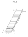
- FIG. 2 is a view schematically showing the winding structure according to the shape of first and second bar-type soft magnetic cores 1 and 2 of FIG. 1 being formed on the printed circuit board.
- FIGS. 3A through 3F are timing views for explaining the operation of the fluxgate sensor of FIG. 2.
- FIG. 3A is a waveform of a magnetic field generated from a first soft magnetic core 1
- FIG. 3B is a waveform of a magnetic field generated from a second soft magnetic core
- FIG. 3C is a waveform of a flux density generated from the first soft magnetic core 1
- FIG. 3D is a waveform of a flux density generated from the second soft magnetic core 2
- FIGS. 3E and 3F are waveforms for respectively showing first and second induction voltages Vind1 and Vind2 induced at the pick-up coil, and the sum of the first and second induction voltages Vind1+Vind2.
- the excitation coil 3 winding the first and second bar-type soft magnetic cores 1 and 2 altogether in the pattern of number '8' (FIGS. 1 and 2) and with the supply of AC excitation current, the internal magnetic field (Hext+Hexc) and flux density (Bext+Bexc) at the first bar-type soft magnetic core 1 and the internal magnetic field (Hext-Hexc) and flux density (Bext-Bexc) at the second bar-type soft magnetic core 2 are in opposite directions (FIGS. 3A, 3B, 3C, 3D).
- Hext is the external magnetic field
- Hexc is the magnetic field by excitation coil
- Bext is the flux density by the external magnetic field
- Bexc is the flux density by the excitation coil.
- the pick-up coil 4 is wound to gain a sum of the flux generated from the first and second bar-type soft magnetic cores 1 and 2, and to detect the changes in the flux by the electronic induction by the AC excitation current. Since the internal magnetic fields of the first and second bar-type soft magnetic cores 1 and 2 are in opposite directions, the induction voltage detected at the pick-up coil 4 is the result of offsetting the two symmetrically generated induction voltages Vind1 and Vind2 (FIG. 3F). In other words, since the external magnetic field Hext is applied to the first and second bar-type soft magnetic cores 1 and 2 in the same direction, the internal magnetic fields of the first and second bar-type soft magnetic cores 1 and 2 are Hext+Hexc and Hext-Hexc.
- the fluxgate sensor integrated into the printed circuit board it is important to bond: the first and second bar-type soft magnetic cores 1 and 2 mounted in the vertical direction; the excitation coil 3 having the united structure in a number '8' pattern; and the pick-up coil 4 winding the first and second bar-type soft magnetic cores 1 and 2 in a solenoid pattern so as to obtain the sum of the flux changes in the first and second bar-type soft magnetic cores 1 and 2, on the same plane as the outer contour of the excitation coil 3.
- the detection of a magnetic field is also possible using the structure of a single soft magnetic core being arranged with the excitation coil and the pick-up coil.
- This case requires more complicated signal processing of the output from the detecting coil, such as amplification and filtering, because there are induction voltage waves generated at the detection coil by the larger excitation coil even in the absence of the external magnetic field. Accordingly, using the two bar-type cores, or a single rectangular-ring type core, will allow more advantages, especially in terms of signal processing requirements.
- FIGS. 4A through 41 are sectional views taken on line I-I of FIG. 1, for showing the process of producing the fluxgate sensor integrated in the printed circuit board.
- the fluxgate sensor uses a first substrate, which is formed of two copper plates 21 and 23 each being adhered to one and the other sides of a prepreg 22 (FIG. 4A).
- the second substrate is formed by the bonding of a prepreg 24 and soft magnetic layer 25 onto the etched upper portion of the first substrate (FIG. 4C).
- the pattern for the first and second soft magnetic cores 1 and 2 is formed.
- the first and second soft magnetic cores 1 and 2 are formed (FIG. 4D).
- via holes 28 are formed through the third substrate, at locations horizontally distanced from the first and second bar-type soft magnetic cores 1 and 2 (FIG. 4F).
- the respective via holes are metal-plated (FIG. 4G).
- the next processes are: forming a pattern for the excitation coil 3 and the pick-up coil 4 by using photosensitive paint and an exposure on the copper plates adhered to one and the other sides of the third substrate; and then forming the excitation coil 3 and the pick-up coil 4 through etching (FIG. 4H).
- the excitation coil 3 is patterned to have a structure of alternately winding, together with the excitation coil of FIG. 4B, the upper (first) and lower (second) bar-tpye soft magnetic cores 1 and 2 altogether and substantially in a number '8' pattern.
- the pick-up coil 4 is formed to have a structure of winding the upper (first) and lower (second) bar-type soft magnetic cores 1 and 2 altogether and substantially in a solenoid pattern.
- a pad is formed by using a solder mask on the upper portion of the third substrate for electrical conductivity, and the upper portion of the pad is metal-plated with gold (not shown).
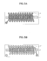
- FIGS. 5A through 5D are plan views showing the fluxgate sensor formed on the printed circuit board according to the preferred embodiment of the present invention.
- FIG. 5A is a plan view showing the shape of one end 3' of the excitation coil, winding the upper (first) magnetic core 1 of the two bar-type soft magnetic cores 1 and 2
- FIG. 5B is a plan view showing the shape of one end 3" of the excitation coil, winding the lower (second) magnetic core 2 of the two bar-type soft magnetic cores 1 and 2.
- the excitation coils 3' and 3" of FIGS. 5A and 5B are connected with each other, and wind the upper (first) and lower (second) soft magnetic cores 1 and 2 in alternate fashion.
- FIG. 5C is a plan view showing the shape of the pick-up coil 4 winding the upper (first) and lower (second) bar-type soft magnetic cores 1 and 2 altogether
- FIG. 5D is a plan view showing the shape of the excitation coil and the pick-up coil winding the upper (first) and lower (second) bar-type soft magnetic cores 1 and 2 altogether.
- the fluxgate sensor described above can be used in various applications, for example, but not by way of limitation, a navigation system by terrestrial magnetism detection, an earth magnetism change monitor (earthquake prediction), a biological electric measurement instrument, and a device for detecting defects in metals.
- the fluxgate sensor can also be used in magnetic encoders, contactless potentiometers, electric current sensors, torque sensors, and displacement sensors.
- the fluxgate sensor which can be integrated in the printed circuit board together with other sensors and circuits, the overall size of a system is reduced greatly. Also, as the voltages induced from the respective cores of sides are driven variably, sensitivity is kept high to detect even a weak external magnetic field.
- the fluxgate sensor according to the present invention can be produced at a cheaper price than the bar-type cores or annular cores, mass-production is enabled.
Landscapes
- Physics & Mathematics (AREA)
- Condensed Matter Physics & Semiconductors (AREA)
- General Physics & Mathematics (AREA)
- Measuring Magnetic Variables (AREA)
- Hall/Mr Elements (AREA)
Applications Claiming Priority (2)
| Application Number | Priority Date | Filing Date | Title |
|---|---|---|---|
| KR10-2002-0013753A KR100464098B1 (ko) | 2002-03-14 | 2002-03-14 | 인쇄회로기판에 집적된 자계검출소자 및 그 제조방법 |
| KR2002013753 | 2002-03-14 |
Publications (2)
| Publication Number | Publication Date |
|---|---|
| EP1345037A2 true EP1345037A2 (de) | 2003-09-17 |
| EP1345037A3 EP1345037A3 (de) | 2006-01-25 |
Family
ID=27764644
Family Applications (1)
| Application Number | Title | Priority Date | Filing Date |
|---|---|---|---|
| EP02021236A Withdrawn EP1345037A3 (de) | 2002-03-14 | 2002-09-18 | In einer Leiterplatte integrierte Förstersonde und dessen Herstellungsverfahren |
Country Status (6)
| Country | Link |
|---|---|
| US (2) | US6998840B2 (de) |
| EP (1) | EP1345037A3 (de) |
| JP (1) | JP3712389B2 (de) |
| KR (1) | KR100464098B1 (de) |
| CN (1) | CN1206541C (de) |
| TW (1) | TW556474B (de) |
Cited By (1)
| Publication number | Priority date | Publication date | Assignee | Title |
|---|---|---|---|---|
| US11366181B2 (en) | 2017-03-31 | 2022-06-21 | At&S Austria Technologie & Systemtechnik Aktiengesellschaft | Component carrier with integrated flux gate sensor |
Families Citing this family (17)
| Publication number | Priority date | Publication date | Assignee | Title |
|---|---|---|---|---|
| EP1450176A1 (de) * | 2003-02-21 | 2004-08-25 | Liaisons Electroniques-Mecaniques Lem S.A. | Magnetfeldsensor und Strommesser |
| KR100579483B1 (ko) * | 2004-08-09 | 2006-05-15 | 삼성전기주식회사 | 자기장 왜곡을 자동 보정하는 지자기 센서 및 그 방법 |
| KR100691467B1 (ko) * | 2005-10-19 | 2007-03-09 | 삼성전자주식회사 | CoNbZr 자성코어를 포함하는 플럭스게이트 센서 및그 제작 방법 |
| KR100683871B1 (ko) * | 2005-11-03 | 2007-02-15 | 삼성전자주식회사 | 마이크로 플럭스 게이트 센서 제조방법 |
| KR100667296B1 (ko) * | 2005-11-18 | 2007-01-12 | 삼성전자주식회사 | 마이크로 플럭스 케이트 센서 제조방법 |
| CN101410723B (zh) * | 2006-03-31 | 2011-09-14 | 西铁城电子股份有限公司 | 磁传感器元件和使用该元件的磁传感器 |
| KR100787228B1 (ko) * | 2006-06-12 | 2007-12-21 | 삼성전자주식회사 | 2축 지자기 센서 및 그 제작방법 |
| US7412892B1 (en) | 2007-06-06 | 2008-08-19 | Measurement Specialties, Inc. | Method of making pressure transducer and apparatus |
| TWI438460B (zh) | 2009-05-21 | 2014-05-21 | Fujikura Ltd | 磁通閘感測器及使用該感測器之電子羅盤 |
| US9000759B2 (en) * | 2010-12-22 | 2015-04-07 | Ncr Corporation | Magnetic sensor |
| US9659246B1 (en) | 2012-11-05 | 2017-05-23 | Dynamics Inc. | Dynamic magnetic stripe communications device with beveled magnetic material for magnetic cards and devices |
| US9010644B1 (en) | 2012-11-30 | 2015-04-21 | Dynamics Inc. | Dynamic magnetic stripe communications device with stepped magnetic material for magnetic cards and devices |
| US9618541B1 (en) * | 2016-04-20 | 2017-04-11 | Neilsen-Kuljian, Inc. | Apparatus, method and device for sensing DC currents |
| US10257933B1 (en) * | 2017-09-26 | 2019-04-09 | Google Llc | Transverse circuit board to route electrical traces |
| US20190156985A1 (en) * | 2017-11-21 | 2019-05-23 | Pi Inc. | High accuracy tuning of resonant network |
| KR102649010B1 (ko) | 2020-03-05 | 2024-03-20 | 한국전자통신연구원 | Rf 미소 자계 검출 센서 및 그 제조 방법 |
| US12241865B2 (en) * | 2020-08-04 | 2025-03-04 | Brown University | Magnetic gradiometer based on magnetic tunnel junctions in magnetic vortex state (vortex MTJ) |
Family Cites Families (19)
| Publication number | Priority date | Publication date | Assignee | Title |
|---|---|---|---|---|
| JPS53155669U (de) * | 1978-03-30 | 1978-12-07 | ||
| US5370766A (en) * | 1993-08-16 | 1994-12-06 | California Micro Devices | Methods for fabrication of thin film inductors, inductor networks and integration with other passive and active devices |
| JP3545074B2 (ja) * | 1994-12-27 | 2004-07-21 | 独立行政法人 科学技術振興機構 | 半導体基板に集積される磁気検出素子及び磁気検出モジュール |
| JPH08233927A (ja) * | 1995-02-27 | 1996-09-13 | Shimadzu Corp | 薄膜フラックスゲート磁気センサ及びその製造方法 |
| JP2985079B2 (ja) * | 1997-07-25 | 1999-11-29 | 株式会社トーキン | 磁気センサ |
| KR100480749B1 (ko) * | 1998-07-07 | 2005-09-30 | 삼성전자주식회사 | 차동 솔레노이드형 자계검출소자 및 그 제조방법 |
| JP3341237B2 (ja) * | 1999-03-31 | 2002-11-05 | ミネベア株式会社 | 磁気センサ素子 |
| JP3341036B2 (ja) * | 1999-03-31 | 2002-11-05 | ミネベア株式会社 | 磁気センサ |
| JP3559459B2 (ja) * | 1998-12-14 | 2004-09-02 | 株式会社東芝 | 磁界センサ |
| JP2001004726A (ja) * | 1999-06-22 | 2001-01-12 | Tdk Corp | 磁界センサ |
| JP2001099903A (ja) * | 1999-09-30 | 2001-04-13 | Citizen Watch Co Ltd | 磁気センサ |
| KR100467839B1 (ko) * | 2002-03-09 | 2005-01-24 | 삼성전기주식회사 | 인쇄회로기판을 사용한 미약자계 감지용 센서 및 그 제조방법 |
| KR100464093B1 (ko) * | 2002-03-13 | 2005-01-03 | 삼성전기주식회사 | 인쇄회로기판에 집적된 자계검출소자 및 그 제조방법 |
| KR100464097B1 (ko) * | 2002-03-14 | 2005-01-03 | 삼성전자주식회사 | 반도체기판에 집적된 자계검출소자 및 그 제조방법 |
| KR100481552B1 (ko) * | 2002-07-30 | 2005-04-07 | 삼성전기주식회사 | 2축 자계검출소자가 집적된 인쇄회로기판 및 그 제조방법 |
| FR2851661B1 (fr) * | 2003-02-24 | 2005-05-20 | Commissariat Energie Atomique | Capteur miniature de champ magnetique |
| KR100503455B1 (ko) * | 2003-06-04 | 2005-07-25 | 삼성전자주식회사 | 아몰포스 자성코어를 사용하여 제조된 마이크로플럭스게이트 센서 및 그 제조 방법 |
| KR100619368B1 (ko) * | 2004-07-05 | 2006-09-08 | 삼성전기주식회사 | 미약자계 감지용 센서를 구비한 인쇄회로기판 및 그 제작방법 |
| KR100619369B1 (ko) * | 2004-07-24 | 2006-09-08 | 삼성전기주식회사 | 미약자계 감지용 센서를 구비한 인쇄회로기판 및 그 제작방법 |
-
2002
- 2002-03-14 KR KR10-2002-0013753A patent/KR100464098B1/ko not_active Expired - Fee Related
- 2002-08-28 US US10/228,948 patent/US6998840B2/en not_active Expired - Fee Related
- 2002-09-18 EP EP02021236A patent/EP1345037A3/de not_active Withdrawn
- 2002-10-16 TW TW091123885A patent/TW556474B/zh not_active IP Right Cessation
- 2002-11-12 CN CNB021504369A patent/CN1206541C/zh not_active Expired - Fee Related
- 2002-12-13 JP JP2002362952A patent/JP3712389B2/ja not_active Expired - Fee Related
-
2005
- 2005-02-22 US US11/061,611 patent/US7087450B2/en not_active Expired - Fee Related
Cited By (1)
| Publication number | Priority date | Publication date | Assignee | Title |
|---|---|---|---|---|
| US11366181B2 (en) | 2017-03-31 | 2022-06-21 | At&S Austria Technologie & Systemtechnik Aktiengesellschaft | Component carrier with integrated flux gate sensor |
Also Published As
| Publication number | Publication date |
|---|---|
| CN1445557A (zh) | 2003-10-01 |
| EP1345037A3 (de) | 2006-01-25 |
| KR100464098B1 (ko) | 2005-01-03 |
| CN1206541C (zh) | 2005-06-15 |
| US6998840B2 (en) | 2006-02-14 |
| JP3712389B2 (ja) | 2005-11-02 |
| US20050172480A1 (en) | 2005-08-11 |
| KR20030073959A (ko) | 2003-09-19 |
| JP2003270309A (ja) | 2003-09-25 |
| US20030173961A1 (en) | 2003-09-18 |
| TW556474B (en) | 2003-10-01 |
| US7087450B2 (en) | 2006-08-08 |
Similar Documents
| Publication | Publication Date | Title |
|---|---|---|
| US7407596B2 (en) | Fluxgate sensor integrated in printed circuit board and method for manufacturing the same | |
| US7087450B2 (en) | Fabricating method for a fluxgate sensor integrated in printed circuit board | |
| EP1441234B1 (de) | In einem Halbleitersubstrat integrierte Förstersonde und dessen Herstellungsverfahren | |
| US7372261B2 (en) | Printed circuit board integrated with a two-axis fluxgate sensor and method for manufacturing the same | |
| US20040124836A1 (en) | Weak-magnetic field sensor using printed circuit board technology and method of manufacturing the same | |
| US6650112B2 (en) | Magnetics impedance element having a thin film magnetics core | |
| JP2003004831A (ja) | 直交フラックスゲート型磁気センサ | |
| US7557571B2 (en) | Fluxgate sensor integrated in semiconductor substrate and method for manufacturing the same | |
| JP2001004726A (ja) | 磁界センサ | |
| KR100536837B1 (ko) | 반도체기판에 집적된 자계검출소자 및 그 제조방법 | |
| KR100485591B1 (ko) | 자기 임피던스 효과를 이용한 극소형 미세자계검출센서 및그제조방법 | |
| KR100617991B1 (ko) | 센서의 감도 및 분해능을 향상시킬 수 있는 플럭스게이트형 미세자계검출센서 | |
| KR20040050128A (ko) | 다층 pcb 제조공법을 이용한 자기임피던스센서 |
Legal Events
| Date | Code | Title | Description |
|---|---|---|---|
| PUAI | Public reference made under article 153(3) epc to a published international application that has entered the european phase |
Free format text: ORIGINAL CODE: 0009012 |
|
| 17P | Request for examination filed |
Effective date: 20020918 |
|
| AK | Designated contracting states |
Kind code of ref document: A2 Designated state(s): AT BE BG CH CY CZ DE DK EE ES FI FR GB GR IE IT LI LU MC NL PT SE SK TR |
|
| AX | Request for extension of the european patent |
Extension state: AL LT LV MK RO SI |
|
| PUAL | Search report despatched |
Free format text: ORIGINAL CODE: 0009013 |
|
| AK | Designated contracting states |
Kind code of ref document: A3 Designated state(s): AT BE BG CH CY CZ DE DK EE ES FI FR GB GR IE IT LI LU MC NL PT SE SK TR |
|
| AX | Request for extension of the european patent |
Extension state: AL LT LV MK RO SI |
|
| RIC1 | Information provided on ipc code assigned before grant |
Ipc: G01R 33/09 20060101AFI20051205BHEP |
|
| AKX | Designation fees paid |
Designated state(s): AT BE BG CH CY CZ DE DK EE ES FI FR GB GR IE IT LI LU MC NL PT SE SK TR |
|
| 17Q | First examination report despatched |
Effective date: 20100721 |
|
| STAA | Information on the status of an ep patent application or granted ep patent |
Free format text: STATUS: THE APPLICATION IS DEEMED TO BE WITHDRAWN |
|
| 18D | Application deemed to be withdrawn |
Effective date: 20101201 |