EP1345092A2 - Procédé de fixation de révélateur sur un matériau à imprimer et dispositif à micro-ondes - Google Patents
Procédé de fixation de révélateur sur un matériau à imprimer et dispositif à micro-ondes Download PDFInfo
- Publication number
- EP1345092A2 EP1345092A2 EP02025127A EP02025127A EP1345092A2 EP 1345092 A2 EP1345092 A2 EP 1345092A2 EP 02025127 A EP02025127 A EP 02025127A EP 02025127 A EP02025127 A EP 02025127A EP 1345092 A2 EP1345092 A2 EP 1345092A2
- Authority
- EP
- European Patent Office
- Prior art keywords
- resonator chamber
- printing material
- microwave device
- toner
- microwave
- Prior art date
- Legal status (The legal status is an assumption and is not a legal conclusion. Google has not performed a legal analysis and makes no representation as to the accuracy of the status listed.)
- Withdrawn
Links
Images


Classifications
-
- G—PHYSICS
- G03—PHOTOGRAPHY; CINEMATOGRAPHY; ANALOGOUS TECHNIQUES USING WAVES OTHER THAN OPTICAL WAVES; ELECTROGRAPHY; HOLOGRAPHY
- G03G—ELECTROGRAPHY; ELECTROPHOTOGRAPHY; MAGNETOGRAPHY
- G03G15/00—Apparatus for electrographic processes using a charge pattern
- G03G15/20—Apparatus for electrographic processes using a charge pattern for fixing, e.g. by using heat
Definitions
- the invention relates to a method for attaching toner to a Printing material by heating according to claim 1 and on a microwave device, in particular for performing the method according to claim 4.
- a toner material is applied to various printing processes applied a substrate.
- the toner material or securely attach the toner to the substrate or interlock with it.
- the toner should be firm and without smearing on the substrate be fixed.
- Fixing rollers are often used for this purpose, which attack with heat and pressure on both sides of the concrete substrate and the toner applied to the substrate in various ways melt and fix. This has disadvantages, such as wear the fuser rollers and the risk of damage to the substrate.
- a Solution consists in the use of contactless fixing devices, which the substrate when fixing or attaching the toner to the substrate do not touch. Fixing by means of microwave radiation is one of the prior art when the substrate runs through a microwave resonator proposed.
- a termination slide or short circuit slide on a microwave device for setting the resonance state or the resonance condition requires good contacting to be electrical To avoid rollovers and is for the high number of adjustments for various substrates are unsuitable.
- the object of the invention is therefore the fixing of toner to a printing material to ensure quickly and easily.
- Another object of the invention is the fixing of toner to different types of substrates on suitable Way to adjust.
- the invention solves the problem with the features of claims 1 and 4.
- a process for attaching toner to a substrate Heating in which the printing material through a passage in a resonator chamber a microwave device is carried out and at least one element moved to tune the resonance state in the resonator chamber becomes.
- a microwave device for attaching toner to one Substrate provided by heating, in particular for performing the A method according to claim 1, having a resonator chamber with at least one Passage for passing the printing material and at least one into the resonator chamber reaching element for tuning the resonance state by moving the element. Is the state of resonance or the resonance condition fulfilled in the microwave device, the microwave radiation couples the Microwave device in the substrate and heats it.
- toner becomes contactless and on fixed in a simple way on the substrate and which is used to absorb the microwave power resonance tuning of the microwave device required by the printing material can be easily and inexpensively adjusted to different substrates.
- the element is formed from a material with low dielectric losses, preferably from polytetrafluoroethylene.
- the element has a cross section of 8 mm in length and 6 mm in width, and the element occupies two different positions in the resonator chamber for setting a resonance state.
- the one resonance state or the one resonance condition to which a position of the element or tuning element is assigned is selected in order to fix toner on printing materials of one type, for example printing materials of a certain weight range.
- a different resonance state, to which a different position of the element or tuning element is assigned, is selected in order to fix toner on printing materials of a different type, for example in a different weight range.
- the temperature of the substrate or fixing temperature in the resonator chamber can be adjusted with two positions of the element for different substrate weights. Further settings of the positions of the element are not necessary.
- FIG. 1 shows three function profiles of the maximum temperature of a paper or printing material 1 as a function of paper weights or printing material weights for different sizes of an aperture in a resonator chamber 3 of a microwave device.
- the measurements were carried out at a constant microwave power of the microwave device of 2000 W.
- the temperature of the printing material 1 was measured after leaving the resonator chamber 3 through a passage 7 'by means of a line pyrometer.
- the speed of printing material 1 was a constant 50 cm / s during the measurements.
- the abscissa shows the weight of the substrate or paper in grams per square meter
- the ordinate shows the maximum paper temperature in degrees Celsius as a function of the weight of the paper, which arises as a result of the heating of the substrate 1 or paper due to the microwave radiation of the microwave device.
- the absorption of the microwave radiation by the printing material 1 is dependent on the setting of the resonance condition in the resonator chamber 3.
- the embodiment of a resonator chamber 3 used has a width of 30 mm. When the printing material 1 extends completely through the resonator chamber 3, there is approximately a section of 24 mm of the printing material 1 (30 mm less the wall thicknesses of the resonator chamber 3) therein.
- the curves of the function curves are designated a, b and c, in which different aperture sizes are used in each case.
- the diaphragm is located on the side of the resonator chamber 3, on which a microwave is coupled into the resonator chamber 3.
- a standing microwave can be formed in the resonator chamber 3 with the aid of the aperture.
- the curve with the designation a describes a function course in a resonator chamber 3 with an orifice with a length of 50 mm and a width of 17 mm
- the curve with the designation b describes a function course with a resonator chamber 3 with an orifice with a length of 54.5 mm and the width 17 mm
- the curve with the designation c describes a function course in a resonator chamber 3 without an aperture.
- a design of the resonator chamber 3 without an aperture means that the microwave can enter and leave the resonator chamber 3 with internal dimensions of 94 mm length and 24 mm width without any obstacle.
- curve a runs in an arc shape with a maximum of the paper weight in the range of approximately 180 g / m 2 .
- Curve b is arcuate, flatter in comparison to curve a with a maximum paper weight in the range of approximately 200 g / m 2 .
- Curve c runs very flat, almost parallel to the abscissa, with a slight arch shape and a maximum paper weight in the range of approximately 180 g / m 2 . It was found that the larger the aperture used, the flatter the course of the function.
- the functional dependencies shown in FIG. 1 are essentially caused by using the diaphragms at the coupling opening of the microwave radiation into the resonator chamber 3.
- the maximum paper temperature as a function of different paper weights for different positions of the element 4 in the passage 7, 7 'of the resonator chamber 3.
- the measurements were carried out at a constant microwave power of the microwave device of 2000 W.
- the element 4 was moved in the resonator chamber 3, the size of the aperture at the coupling opening, at which the microwave radiation is coupled into the resonator chamber, is provided with a length of 54.5 mm and a width of 17 mm in a rectangular configuration ,
- the ordinate denotes the maximum temperature of the paper or printing material 1, which is caused by the microwave radiation from the microwave device.
- the element 4 is a rod made of polytetrafluoroethylene (PTFE), known under the brand name Teflon, which extends into the resonator chamber 3.
- PTFE polytetrafluoroethylene
- the curves in Fig. 2 are marked with the letters d and e.
- the curve e describes the course of the maximum printing material temperature or paper temperature as a function of the printing material weight or paper weight at a position of the element 4 which is shifted by 40 mm compared to the position of the element 4, which the curve d describes. The influence of the position of element 4 on the maximum paper temperature can be seen.
- the courses of the curves d and e, which characterize different positions of the element 4, differ markedly from one another. Similar dependencies are obtained for all different embodiments of element 4, as described in the figures.
- This effect is used in the present invention to change the resonance tuning of the microwave device by moving the element 4 and as a result to change the temperature of the printing material 1 or paper as it passes through the microwave device by absorbing the microwave energy and converting the microwave energy into thermal energy.
- the position of the element 4, in this case a Teflon rod, according to curve d is used for paper or printing material weights of up to approximately 250 g / m 2 , and for printing material weights of 250 g / m 2 and higher the element 4 is shifted by 40 mm in order to achieve the maximum paper temperature according to curve e, which is higher in this area than the maximum paper temperature of curve d. In this way, a rapid adjustment of the microwave device to the substrate weight or paper weight is achieved.
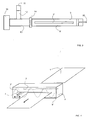
- FIG. 3 shows an example of a schematic side section of an embodiment a microwave device for fixing toner on printing material 1.
- a magnetron 10 for generation of microwaves.
- a coupling converter is connected to the magnetron 10 13 for coupling the microwaves into the resonator chamber 3.
- Farther a water load 11 and a circulator 12 are provided.
- the resonator chamber 3 has a passage 7 'in the side surface 9 'for passing printing material 1 through the resonator chamber 3 on.
- a corresponding passage 7 In the opposite side surface 9 of the resonator chamber 3 there is a corresponding passage 7.
- the end slide 15 On the right side of the resonator chamber 3 of the microwave device there is a terminating slide 15 made of metal, which is movable in the horizontal direction to the resonator chamber 3 and extends into the resonator chamber 3.
- the end slide 15 consists of a rod and a rectangular surface that is perpendicular to the rod which closes the resonator chamber 3 such that a good electrical There is contact to the inside of the resonator chamber 3.
- 3 represents a microwave device of the prior art and will not be described further.
- FIG. 4 shows a schematic perspective view of a resonator chamber 3 of an embodiment of the invention, which is comprised by a microwave device.
- the microwave device is similar to that of FIG. 3, is powered by a voltage supply and comprises the magnetron 10 for generating the microwave radiation, the circulator 12 with a water load 11, the coupling converter 13 for inductively adapting the magnetron 10 to the resonator chamber 3 and is with the Resonator chamber 3 connected by means of a coupling opening 14.
- the coupling opening 14 of the resonator chamber 3 there is an aperture, as described above.
- the geometry of the resonator chamber 3 is designed together with the diaphragm and the end slide 15 in such a way that a standing microwave is pronounced in the resonator chamber 3.
- the microwave radiation in the resonator chamber 3 is represented schematically by a sinusoidal wave.
- the resonator chamber 3 each has a passage 7, 7 'on the opposite side surfaces 9 and 9', which are designed so that the printing material 1 is fed to the resonator chamber 3 on one side surface 9 through the passage 7 and the resonator chamber 3 leaves the opposite other side surface 9 'through the passage 7'.
- the direction of movement of the printing material 1 is shown by the direction arrow.
- the paper temperature is only slightly dependent on the paper weight per area. The maximum temperature of the printing material 1 is low in this case. By using an aperture, however, there are significant dependencies between the paper temperature and the paper weight per area, as shown in FIG.
- the maximum temperature of the printing material 1 is higher than without an aperture.
- Typical sizes of the diaphragm are 50 mm in length with a width of 17 mm and 54.5 mm in length with a width of 17 mm, the side opening of the resonator chamber 3, which adjoins the coupling opening 14 with the diaphragm, a length of 94 mm and a width of 24 mm. Without using an aperture, the microwave is coupled into the resonator chamber 3 through the latter size of the opening.
- circular shutters are also used.
- the element 4 With a side surface 9, 9 'of the resonator chamber 3, the element 4 extends through at least one passage 7, 7' into the interior of the resonator chamber 3. Alternatively, the element 4 can reach into the resonator chamber 3 through a further opening.
- the presence of the element 4 in the resonator chamber 3 changes the resonance state or the resonance condition in the resonator chamber 3.
- the position of the element 4 influences the resonance condition in the resonator chamber 3 and adjusts the resonance condition to the printing material 1 located in the resonator chamber 3. In this way, the changing paper or substrate temperature with different paper or substrate weights is taken into account when fixing toner, as shown in FIG. 1.
- a movement, in this case a change in position in the horizontal direction, of the element 4 ultimately has the effect that, with changing paper or printing material weights per surface, the paper or printing material temperature remains almost constant when the printing material 3 passes through the resonator chamber 3 without the power supply on the microwave device is increased by the voltage source.
- the element 4 in the passage 7 ' is displaced longitudinally to the passage 7', for example, so that with a basis weight of 100 g / m 2 a maximum temperature of the printing material 1 according to curve d is reached and at a basis weight of 300 g / m 2 a maximum temperature of the printing material 1 according to curve e is reached.
- This effect is based on the fact that the absorption of microwaves by the printing material 1 in the resonator chamber 3 is dependent on the setting of the resonance condition in the resonator chamber 3.
- the printing material 1 and the element 4 together influence the resonance condition.
- the invention achieves an increased energy yield by moving the element 4 into the appropriate position.
- Assignment tables are carried out which uniquely determine a specific basis weight of a printing material 1 as a function of the size of the passage 7, 7 ', the power at the microwave device and the speed at which the printing material 1 is moved through the resonator chamber 3 Assign the position of the element 4 exactly in such a way that the printing material 1 and the element 4 together result in an optimal resonance condition in the resonator chamber 3.
- the basis weight of the printing material 1 is generally known in the control device of the printing press, in particular in digital printing presses in which different printing materials 1 with different masses are printed in rapid succession.
- the element 4 is preferably moved by a suitable controller depending on the data outputs of the assignment table. Stepper motors can advantageously be used for certain embodiments of element 4. A further possibility of moving the element 4 is provided by controlling a magnet coupled to the element 4, which is electrically controlled and moves the element 4. By moving the element 4, the resonance condition in the resonator chamber 3 is always adjusted in such a way that the printing material 1 and the toner lying thereon are heated in an energy-efficient manner in order to fix the toner to the printing material 1. Variants of the invention disclose different movement possibilities for different structural embodiments of the element 4. If the element 4 is designed as a rod, in principle all movement possibilities are given. As shown in FIG.
- the element 4 is designed as a guided plate which is moved into a wall of the resonator chamber 3 parallel to it, various local arrangements and directions of movement can also be realized for this embodiment, for example the plate is located on the side of the end slide 15 on which Diaphragm side or on the side walls in the longitudinal direction of the resonator chamber 3 or side surfaces 9, 9 '.
- the resonance behavior in the resonator chamber 3 changes with different elements 4 and different directions of movement of the element 4.
- the respective assignment table for controlling the position of the element 4 is adapted to the embodiment of the element 4 and to the direction of movement of the element 4.
- a particularly advantageous embodiment of the invention discloses the element 4 with two different positions in the resonator chamber 3, which are sufficient to suitably match the resonance condition in the resonator chamber 3 for different printing substrates 1 and grammages or weight per surface of the printing substrate 1, so that with constant power the microwave device always achieves a high paper temperature and suitable fixing of the toner to the printing material 1.
- Another variant relates to the case when the printing material 1 is in the process of entering the resonator chamber 3 through the passage 7 and exiting from the latter through the passage 7 '. When the printing material 1 enters and exits, the printing material 1 does not extend completely through the resonator chamber 3.
- the resonance condition of the microwave device is matched to the fact that the printing material 1 extends completely through the resonator chamber 3, that is to say to the weight of the printing material 1 in this case.
- the effective weight of the printing material 1 in the resonator chamber 3 is smaller than in the case when the printing material 1 extends completely through the resonator chamber 3.
- This reduced effective weight of the printing material 1 in the resonator chamber 3 means that the resonance condition in the resonator chamber 3 is not fulfilled and the front edge and the rear edge of the printing material 3 are not heated to the temperatures suitable for fixing the toner.
- the position of the element 4 changes depending on the position of the printing material 1 in the resonator chamber 3.
- the element 4 controlled by the stepping motor, assumes a position which leads to a first resonance tuning in the resonator chamber 3. If the printing material 1 extends through the resonator chamber 3 completely from one side surface 9 with the first passage 7 to the opposite side surface 9 ′ with the passage 7 ′, the element 4 changes the position, this leads to a different resonance tuning in the resonator chamber 3.
- the position of the printing material 1 can be determined by means of sensors in the resonator chamber 3, which for example detect the front edge of the printing material 1.
- the speed of the printing material 1 can be used to determine whether the printing material 1 is at the inlet or when it exits into the passage 7 or from the passage 7 ', thus appropriately controlling the position of the Elements 4 is made possible.
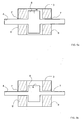
- 5a and 5b each show a lateral section of the resonator chamber 3 of the microwave device.
- element 4 is designed as a variant rotatable about its own axis.
- the arrangement of axis or axis of rotation and wing 8 to each other and the storage of the element 4 is arbitrary.
- 5a shows a variant of the element 4 in a first position.
- the element 4 is in this case designed as a rod, which extends from the passage 7 in a side surface 9 of the resonator chamber 3 through the passage 7 'of an opposite side surface 9' of the resonator chamber 3.
- the two rectangular wings 8 are formed, which are connected in one piece to the element 4.
- the wings 8 run perpendicular to the element 4 and are offset from one another by 180 ° on the element 4, so that the two wings 8 of the element 4 are arranged in mirror image to one another with a mirror axis which extends axially to the element 4.
- Channels are formed in the resonator chamber 3, in which the standing microwave propagates.
- the interior of the resonator chamber 3 is designed accordingly, the channels being located between the walls 9 of the resonator chamber 3.
- the first position of the element 4 is set for heating a specific printing material 1 with a basis weight of 300 g / m 2 .
- the printing press is operated with another printing material 1 after fixing the printing material 1 with a basis weight of 300 g / m 2 , for example with a printing material 1 with a basis weight of 80 g / m 2 , the position of the element 4 according to FIG 5a insufficient heating has been achieved.
- a stepping motor causes the element 4 to rotate into a second position according to FIG. 5b, as shown by the arrow. In the second position of the element 4, the printing material 1 with a basis weight of 80 g / m 2 is heated in a suitable manner in order to fix the toner.
- FIG. 6 shows a view of an embodiment of the resonator chamber 3 and the like Element 4 in a further embodiment as a membrane, which depends on in the resonator chamber 3 blown compressed air, as through the double-sided Arrow 16 shown, or a negative pressure generated in the resonator chamber 3 their shape changes.
- the membrane changes with the exception of the appropriate one Attachment points of the membrane their position in the resonator chamber 3, this leads to different resonance states in the resonator chamber 3. It a changed position 4 'of the element 4 is shown for the case that overpressure or underpressure is used in the resonator chamber 3.
- This embodiment of the element 4 can be used particularly advantageously in one Embodiment of a resonator chamber 3, into which the microwaves from below couple through a coupling opening 14 with the screen and the printing material 1 in the resonator chamber 3 in a plane lying above the coupling opening 14 passes.
- FIG. 7 shows a view of an embodiment of the resonator chamber 3 and the like Element 4 or tuning element in a further embodiment as suitable dielectric liquid which can be inserted into a tube 17 which has a suitable diameter and runs through the resonator chamber 3.
- the tube 17 is suitably provided with a reservoir container 18 connected, in which the element 4 is located as a liquid, so that the liquid introduced into the tube 17 by a suitable device and again can be left out.
- This is advantageously done by the resonator chamber 3 leading tubes 17 a suitable inclination, so that ensured is that all of the liquid gets back into the reservoir container 18.
- the resonance state in the resonator chamber 3 and the heating of the printing material 1 can be controlled in a targeted manner.
- a liquid MOTON TEFLON ADDITIV 102 for example, is a good choice colloidal dispersion of PTFE / TEFLON ⁇ particles in an oil.
- a suitable tub instead of the tube 17 for the appropriate absorption and release of liquid into the resonator chamber 3 are introduced, with which the tuning of the microwave device is adaptable to different substrates 1.
Landscapes
- Physics & Mathematics (AREA)
- General Physics & Mathematics (AREA)
- Fixing For Electrophotography (AREA)
- Constitution Of High-Frequency Heating (AREA)
Applications Claiming Priority (2)
| Application Number | Priority Date | Filing Date | Title |
|---|---|---|---|
| DE10210936A DE10210936C1 (de) | 2002-03-13 | 2002-03-13 | Verfahren für das Befestigen von Toner an einem Bedruckstoff und Mikrowelleneinrichtung |
| DE10210936 | 2002-03-13 |
Publications (2)
| Publication Number | Publication Date |
|---|---|
| EP1345092A2 true EP1345092A2 (fr) | 2003-09-17 |
| EP1345092A3 EP1345092A3 (fr) | 2006-02-22 |
Family
ID=27762891
Family Applications (1)
| Application Number | Title | Priority Date | Filing Date |
|---|---|---|---|
| EP02025127A Withdrawn EP1345092A3 (fr) | 2002-03-13 | 2002-11-09 | Procédé de fixation de révélateur sur un matériau à imprimer et dispositif à micro-ondes |
Country Status (3)
| Country | Link |
|---|---|
| EP (1) | EP1345092A3 (fr) |
| JP (1) | JP3890028B2 (fr) |
| DE (1) | DE10210936C1 (fr) |
Cited By (4)
| Publication number | Priority date | Publication date | Assignee | Title |
|---|---|---|---|---|
| EP1489469A1 (fr) * | 2003-06-16 | 2004-12-22 | Eastman Kodak Company | Dispositif à micro-ondes pour fixation de révélateur sur un matériau à imprimer et son élément à utiliser |
| WO2005029200A1 (fr) * | 2003-09-18 | 2005-03-31 | Eastman Kodak Company | Micro-ondes fixant un toner sur un tirage |
| DE102005051173A1 (de) * | 2005-10-24 | 2007-04-26 | Eastman Kodak Co. | Verfahren und Vorrichtung zur Beaufschlagung eines flächigen Objektes mit Mikrowellen und Tintenstrahldruckvorrichtung mit einer Mikrowellen-Heizeinrichtung |
| EP2233293A4 (fr) * | 2008-10-07 | 2010-11-17 | Mimaki Eng Kk | Imprimante à jet d'encre |
Families Citing this family (7)
| Publication number | Priority date | Publication date | Assignee | Title |
|---|---|---|---|---|
| JP2005108449A (ja) * | 2003-09-26 | 2005-04-21 | Toyota Central Res & Dev Lab Inc | マイクロ波加熱装置 |
| DE102004004329B4 (de) * | 2004-01-24 | 2010-04-22 | Eastman Kodak Co. | Einrichtung und Verfahren zum Einstellen einer Fixiereinrichtung und Fixiereinrichtung einer digitalen Druckmaschine |
| DE102005056283B4 (de) * | 2005-11-24 | 2009-03-26 | Eastman Kodak Co. | Verfahren und Vorrichtung zur Fixierung von Toner |
| JP5559127B2 (ja) * | 2011-10-31 | 2014-07-23 | 村田機械株式会社 | マイクロ波加熱装置、及びこれを用いた画像定着装置 |
| JP5536743B2 (ja) * | 2011-11-28 | 2014-07-02 | 村田機械株式会社 | マイクロ波加熱装置、及びこれを用いた画像定着装置 |
| JP5792758B2 (ja) | 2012-04-16 | 2015-10-14 | 村田機械株式会社 | マイクロ波加熱装置、及びこれを用いた画像定着装置 |
| DE102014213526A1 (de) * | 2014-07-11 | 2016-01-14 | Homag Holzbearbeitungssysteme Gmbh | Vorrichtung zur Erwärmung einer Funktionsschicht |
Family Cites Families (6)
| Publication number | Priority date | Publication date | Assignee | Title |
|---|---|---|---|---|
| US3478188A (en) * | 1967-10-13 | 1969-11-11 | Varian Associates | Multimode cavity resonator with two coupling holes at wall corners |
| JPS5612673A (en) * | 1979-07-13 | 1981-02-07 | Hitachi Metals Ltd | Fixing device |
| US4435072A (en) * | 1980-12-11 | 1984-03-06 | Canon Kabushiki Kaisha | Image recording apparatus with leakage preventing microwave fixing device |
| JPS6014268A (ja) * | 1983-07-05 | 1985-01-24 | Ricoh Co Ltd | 定着装置 |
| JP3077879B2 (ja) * | 1994-02-15 | 2000-08-21 | インターナショナル・ビジネス・マシーンズ・コーポレ−ション | ウェブ・タイプの定量された処理材料にマイクロ波エネルギーを印加するための装置及び方法 |
| JP3064875B2 (ja) * | 1995-07-07 | 2000-07-12 | 松下電器産業株式会社 | 高周波加熱装置 |
-
2002
- 2002-03-13 DE DE10210936A patent/DE10210936C1/de not_active Expired - Fee Related
- 2002-11-09 EP EP02025127A patent/EP1345092A3/fr not_active Withdrawn
-
2003
- 2003-03-13 JP JP2003068696A patent/JP3890028B2/ja not_active Expired - Fee Related
Cited By (5)
| Publication number | Priority date | Publication date | Assignee | Title |
|---|---|---|---|---|
| EP1489469A1 (fr) * | 2003-06-16 | 2004-12-22 | Eastman Kodak Company | Dispositif à micro-ondes pour fixation de révélateur sur un matériau à imprimer et son élément à utiliser |
| WO2005029200A1 (fr) * | 2003-09-18 | 2005-03-31 | Eastman Kodak Company | Micro-ondes fixant un toner sur un tirage |
| DE102005051173A1 (de) * | 2005-10-24 | 2007-04-26 | Eastman Kodak Co. | Verfahren und Vorrichtung zur Beaufschlagung eines flächigen Objektes mit Mikrowellen und Tintenstrahldruckvorrichtung mit einer Mikrowellen-Heizeinrichtung |
| EP2233293A4 (fr) * | 2008-10-07 | 2010-11-17 | Mimaki Eng Kk | Imprimante à jet d'encre |
| CN101939168B (zh) * | 2008-10-07 | 2012-12-05 | 株式会社御牧工程 | 喷墨打印机 |
Also Published As
| Publication number | Publication date |
|---|---|
| EP1345092A3 (fr) | 2006-02-22 |
| JP3890028B2 (ja) | 2007-03-07 |
| JP2003295692A (ja) | 2003-10-15 |
| DE10210936C1 (de) | 2003-10-09 |
Similar Documents
| Publication | Publication Date | Title |
|---|---|---|
| DE69223934T2 (de) | Methode und Apparat zum Aufrauhen faseroptischer Substrate | |
| EP1345092A2 (fr) | Procédé de fixation de révélateur sur un matériau à imprimer et dispositif à micro-ondes | |
| EP0121772A1 (fr) | Dispositif de rouleau de fusion | |
| AT13360U1 (de) | Vorrichtung und Verfahren zum Auftragen von Farbe auf einen plattenförmigen Gegenstand | |
| EP0387412B1 (fr) | Procédé et dispositif pour revêtir une bande en particulier une bande de papier ou de carton | |
| DE2327423C2 (de) | Mikrowellenheizgerät mit einem Verteilerelement zur Überkopplung von Mikrowellenenergie auf das aufzuheizende Material | |
| DD232880A5 (de) | Laminierstation | |
| EP0520332A1 (fr) | Presse à imprimer avec une forme d'impression à supprimer | |
| DE10145003C2 (de) | Verfahren und Einrichtung zur Erwärmung von Bedruckstoff und/oder Toner | |
| DE102004039684B4 (de) | Vorrichtung zur Aufbringung einer Leitpaste auf eine gekrümmte Harzglasscheibe | |
| EP3796778B1 (fr) | Dispositif de thermorégulation et procédé de thermorégulation | |
| DE19506465C2 (de) | Glättvorrichtung für eine Papierbahn in einer papierverarbeitenden Maschine | |
| DE2645672C3 (fr) | ||
| EP3199041A1 (fr) | Unité de bande aspirante comprenant un dispositif de réglage servant à régler la distance entre un disque de pression de l'unité de bande aspirante et un élément racloir et procédé associé | |
| DE4445506B4 (de) | Ausrollvorrichtung für Teig | |
| EP0469433B1 (fr) | Dispositif pour appliquer une reproduction de feuille gainée sur une voie en matériel flexible | |
| DE19623348B4 (de) | Flüssigkeits-Übertragungsvorrichtung der graphischen Industrie | |
| DE19610273A1 (de) | Umschlossene Mehrklingen-Rakelbaueinheit für Siebdruck | |
| DE2647154C3 (de) | Verfahren zum Verändern des Durchmessers eines Rohres aus einem thermoplastischen Werkstoff | |
| EP1369751B1 (fr) | Méthode et appareil pour le fixage de toner sur un substrat | |
| EP2965888B1 (fr) | Dispositif de chauffage d'une couche fonctionnelle | |
| EP0463213A1 (fr) | Procédé de traitement en surface de bande de papier en mouvement et dispositif pour la mise en oeuvre du procédé | |
| DE10326964B3 (de) | Mikrowelleneinrichtung für das Befestigen von Toner an einem Bedruckstoff und dafür verwendbares Element | |
| EP2966936A1 (fr) | Dispositif de chauffage d'une couche fonctionnelle | |
| DE10145004C2 (de) | Verfahren und Einrichtung zur Erwärmung von Bedruckstoff und/oder Toner |
Legal Events
| Date | Code | Title | Description |
|---|---|---|---|
| PUAI | Public reference made under article 153(3) epc to a published international application that has entered the european phase |
Free format text: ORIGINAL CODE: 0009012 |
|
| AK | Designated contracting states |
Kind code of ref document: A2 Designated state(s): AT BE BG CH CY CZ DE DK EE ES FI FR GB GR IE IT LI LU MC NL PT SE SK TR |
|
| AX | Request for extension of the european patent |
Extension state: AL LT LV MK RO SI |
|
| RAP1 | Party data changed (applicant data changed or rights of an application transferred) |
Owner name: EASTMAN KODAK COMPANY |
|
| PUAL | Search report despatched |
Free format text: ORIGINAL CODE: 0009013 |
|
| AK | Designated contracting states |
Kind code of ref document: A3 Designated state(s): AT BE BG CH CY CZ DE DK EE ES FI FR GB GR IE IT LI LU MC NL PT SE SK TR |
|
| AX | Request for extension of the european patent |
Extension state: AL LT LV MK RO SI |
|
| 17P | Request for examination filed |
Effective date: 20060304 |
|
| AKX | Designation fees paid |
Designated state(s): AT BE BG CH CY CZ DE DK EE ES FI FR GB GR IE IT LI LU MC NL PT SE SK TR |
|
| 17Q | First examination report despatched |
Effective date: 20061013 |
|
| STAA | Information on the status of an ep patent application or granted ep patent |
Free format text: STATUS: THE APPLICATION IS DEEMED TO BE WITHDRAWN |
|
| 18D | Application deemed to be withdrawn |
Effective date: 20070224 |