EP1346889A2 - Capteur de pluie, en particulier pour vitres - Google Patents
Capteur de pluie, en particulier pour vitres Download PDFInfo
- Publication number
- EP1346889A2 EP1346889A2 EP02024777A EP02024777A EP1346889A2 EP 1346889 A2 EP1346889 A2 EP 1346889A2 EP 02024777 A EP02024777 A EP 02024777A EP 02024777 A EP02024777 A EP 02024777A EP 1346889 A2 EP1346889 A2 EP 1346889A2
- Authority
- EP
- European Patent Office
- Prior art keywords
- rain sensor
- radiation
- transmitter
- receiver
- measuring sections
- Prior art date
- Legal status (The legal status is an assumption and is not a legal conclusion. Google has not performed a legal analysis and makes no representation as to the accuracy of the status listed.)
- Granted
Links
Images


Classifications
-
- B—PERFORMING OPERATIONS; TRANSPORTING
- B60—VEHICLES IN GENERAL
- B60S—SERVICING, CLEANING, REPAIRING, SUPPORTING, LIFTING, OR MANOEUVRING OF VEHICLES, NOT OTHERWISE PROVIDED FOR
- B60S1/00—Cleaning of vehicles
- B60S1/02—Cleaning windscreens, windows or optical devices
- B60S1/04—Wipers or the like, e.g. scrapers
- B60S1/06—Wipers or the like, e.g. scrapers characterised by the drive
- B60S1/08—Wipers or the like, e.g. scrapers characterised by the drive electrically driven
- B60S1/0818—Wipers or the like, e.g. scrapers characterised by the drive electrically driven including control systems responsive to external conditions, e.g. by detection of moisture, dirt or the like
- B60S1/0822—Wipers or the like, e.g. scrapers characterised by the drive electrically driven including control systems responsive to external conditions, e.g. by detection of moisture, dirt or the like characterized by the arrangement or type of detection means
-
- B—PERFORMING OPERATIONS; TRANSPORTING
- B60—VEHICLES IN GENERAL
- B60S—SERVICING, CLEANING, REPAIRING, SUPPORTING, LIFTING, OR MANOEUVRING OF VEHICLES, NOT OTHERWISE PROVIDED FOR
- B60S1/00—Cleaning of vehicles
- B60S1/02—Cleaning windscreens, windows or optical devices
- B60S1/04—Wipers or the like, e.g. scrapers
- B60S1/06—Wipers or the like, e.g. scrapers characterised by the drive
- B60S1/08—Wipers or the like, e.g. scrapers characterised by the drive electrically driven
- B60S1/0818—Wipers or the like, e.g. scrapers characterised by the drive electrically driven including control systems responsive to external conditions, e.g. by detection of moisture, dirt or the like
- B60S1/0822—Wipers or the like, e.g. scrapers characterised by the drive electrically driven including control systems responsive to external conditions, e.g. by detection of moisture, dirt or the like characterized by the arrangement or type of detection means
- B60S1/0833—Optical rain sensor
- B60S1/0837—Optical rain sensor with a particular arrangement of the optical elements
-
- B—PERFORMING OPERATIONS; TRANSPORTING
- B60—VEHICLES IN GENERAL
- B60S—SERVICING, CLEANING, REPAIRING, SUPPORTING, LIFTING, OR MANOEUVRING OF VEHICLES, NOT OTHERWISE PROVIDED FOR
- B60S1/00—Cleaning of vehicles
- B60S1/02—Cleaning windscreens, windows or optical devices
- B60S1/04—Wipers or the like, e.g. scrapers
- B60S1/06—Wipers or the like, e.g. scrapers characterised by the drive
- B60S1/08—Wipers or the like, e.g. scrapers characterised by the drive electrically driven
- B60S1/0818—Wipers or the like, e.g. scrapers characterised by the drive electrically driven including control systems responsive to external conditions, e.g. by detection of moisture, dirt or the like
- B60S1/0822—Wipers or the like, e.g. scrapers characterised by the drive electrically driven including control systems responsive to external conditions, e.g. by detection of moisture, dirt or the like characterized by the arrangement or type of detection means
- B60S1/0862—Wipers or the like, e.g. scrapers characterised by the drive electrically driven including control systems responsive to external conditions, e.g. by detection of moisture, dirt or the like characterized by the arrangement or type of detection means including additional sensors
- B60S1/087—Wipers or the like, e.g. scrapers characterised by the drive electrically driven including control systems responsive to external conditions, e.g. by detection of moisture, dirt or the like characterized by the arrangement or type of detection means including additional sensors including an ambient light sensor
Definitions
- the invention relates to a rain sensor, in particular for Disks, according to the genus of the independent claim.
- a rain sensor is already known from DE 198 15 746, which is attached to a motor vehicle window and several Has measuring sections, some of which are inside the disc run. Such a sensor is typically on the Inside of the motor vehicle on the windshield attached, radiation from one in the sensor housing arranged transmitter is sent into the disc. On the glass-air interface on the outside of the Windshield is the radiation when the windshield is dry totally reflected and towards one, also in the case arranged of the rain sensor, directed. to Direction of the radiation are on the disc light guide arranged.
- Transmitters, receivers and light guides are such arranged or designed that when the disk is dry, that is with total reflection, the maximum or minimum Signal is detected by the receiver. Since the discs from Motor vehicles differ depending on the type of vehicle Thickness are for different types of vehicles different sensor arrangements necessary.
- the rain sensor according to the invention with the features of The main claim has the advantage of being optimized on different slice thicknesses on different slices Can be applied without the signal quality and thickness thereby impairing functionality. In this way the sensor can be manufactured in much larger quantities, which reduces the cost of the individual sensor. In addition, the logistics in series production simplified.
- the one has cylindrical elevation that at least one the base element carries the focusing element.
- the Lichtleit analyses the elevation and the focusing element are formed in one piece. So geometric Tolerances are minimized and the light guide body in one Operation, for example made of plastic, injection molded become.
- the measuring section is through at least one transmitter that emits radiation into the disc is able to send, and at least one recipient, the Radiation from the transmitter from the disc on the same Detect disc side is formed.
- Such optical measuring sections have been used in practice proven, are less prone to failure and inexpensive to use Production.
- measuring sections which are the base of a square include, because in this way by means of two transmitters and two receivers four measuring sections are realized. About that In addition, these four measurement sections can be used in a very small space be accommodated.
- Another advantage is the training of the transmitters and To see receivers as semiconductor components in SMD technology, since this minimizes the installation space requirement of the rain sensor becomes.
- a means in the rain sensor is provided to detect the ambient brightness.
- the means can Lighting devices of the motor vehicle controlled on the other hand, conclusions about extraneous light, which shines on the receivers, are closed and the receiver signals are corrected accordingly.
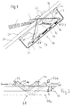
- FIG. 1 shows a rain sensor 10 according to the invention a schematic sectional view.
- This rain sensor 10 essentially comprises a shell-shaped housing 12, which is made of plastic and by one Lichtleitmaschine 14, which is made of plastic - preferably suitably colored PMMA - is closed is.
- the light guide body 14 is by means of a coupling pad 16, which is self-adhesive on both sides as a silicone cushion is formed, attached to a disc 18. It makes sense to have the rain sensor 10 on the Windshield of a motor vehicle in the area that is swept by the windshield wipers.
- the circuit board 20 is located inside the housing 12 attached to the transmitter 22 and receiver 24 as Semiconductor components are arranged in SMD technology.
- the circuit board 20 can also, for example by means of suitable domes, directly on the light guide body 14 be attached.
- the light guide body 14 essentially comprises a flat one Part, from the cylindrical elevations 26 through a lens-like focusing element 27 are completed, protrude.
- light guide body 14 also a flat hologram foil or one directly on or in the disc embossed or exposed hologram as serve beam guiding and / or focusing element 27.
- the transmitter 22 emits radiation 28, which through the focusing elements 27 and the cylindrical ones Elevations 26 at a coupling angle gamma to one Transmitter 22 directed surface 30 of the disc 18 directed becomes.
- Transmitter 22 and receiver 24 as well as the focusing ones Elements 27 are arranged such that at one dry pane 18, so if surface 30 is a glass-air interface forms a total reflection on the Surface 30 takes place.
- the most essential part of Radiation 28 is then in a decoupling angle gamma 'in Reflected towards the receiver 24.
- a detector 34 is also shown, which as Means for detecting the ambient brightness is used and ever after formation of a formation 36 of the light guide body 14, the ambient light from different angular ranges can detect.
- FIG 2 the basic operation of a Rain sensor 10 according to the invention shown.
- the transmitter 22 sends the radiation 28 in the direction of the surface 30 this surface 30 the radiation becomes drier Disc 18 totally reflected and in the direction of the receiver 24 headed. Is the thickness D of the disc greater than provided, for example D ', the radiation 28 arrives no longer entirely to the receiver 24, whereby the signal on Receiver 24 is reduced.
- further receiver 24a arranged such that this Radiation on another surface 30a, the one Disc 18 corresponds to the thickness D ', totally reflected.
- the receivers 24 and 24a can also vary be connected to a large receiver element. Thereby there are measuring sections 38 of different lengths.
- the arrangement of the transmitter 22 and receiver 24 and the Light guide body 14 describes the radiation 28 a Measuring section 38, in the course of which the radiation 28 dry disk 18 totally reflected or when wet Disc is partially reflected.
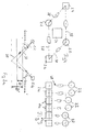
- FIG. 3 shows an arrangement of transmitters 22 and receivers 24 of a rain sensor 10 according to the invention.
- the Entry angle with which the radiation 28 enters the pane 18 occurs are chosen constant so that the Distance between the transmitter 22 and its corresponding one Receiver 24 must be chosen slightly smaller.
- three transmitter pairs 22 and three receiver pairs 24 are shown, each a different distance from each other exhibit. In this way, for different thicknesses D the disc 18 achieves an optimal measurement result.
- the transmitter 22 and the receiver 24 to arrange all measuring sections equally spaced.
- the focusing elements 27 are such aligned that the entry angle gamma of the radiation 28th are different in the disk 18. This is in Figure 3a shown.
- FIG. 4 shows a further arrangement variant of the transmitters 22 and the receiver 24.
- the transmitters 22 and receivers 24 are arranged so that they are in the corners of a Parallelograms are arranged opposite each other. In principle, these can of course also be in another rectangular shape. The key is that the distances between the transmitters 22 with their corresponding receivers 24 each different are in this way for different slice thicknesses to achieve optimal measurement result.
- the detector 34 At the center of the rectangle is the detector 34 for detecting the ambient brightness arranged.
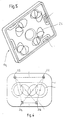
- FIG. 5 shows a light guide body corresponding to one Arrangement shown in Figure 4.
- the surveys 26 with the elements 27 (FIG. 1), however, equidistant from one another arranged. Optimization for the different Slice thickness is achieved in that the angle of incidence the radiation 28 according to FIG. 3a for the different directions are chosen accordingly.
- the transmitters 22 and receivers 24 close the footprint of a trapezoid. Since the transmitter 22 on a parallel of the trapezoid and the receiver 24 on the other parallels of the trapezoid are arranged there are four measuring sections with two different lengths, so that already a large range of different slice thicknesses D can be covered.
- FIG 7 is a light guide body 14 for such Arrangement shown.
- the cylindrical elevations 26 have again the shape of a cylindrical section, the Base of a lens-like element as a focusing Element 27 is complete. Of course, can be equivalent other shapes than the cylindrical can also be provided.
- the formation 36 is also between the two transmitters 22 shown for the detector 34. It is here too possible, for example, by a suitable choice of Angle of incidence for the radiation 28, or by corresponding design of the cylindrical elevations 26 to provide a total of four different measuring sections, with which an even larger pane thickness range can be covered can.
- FIG 8 is another variation of the invention shown.
- a receiver 24 is arranged.
- the Transmitters 22 are each arranged on an arc, in the center of which is the receiver 24.
- Each another transmitter 22 is provided opposite the however, has a smaller distance from the receiver 24.
- the individual transmitters can also be arranged spirally so that each one has a different distance from the receiver 24.
- the signals of the Receiver added, so that there is a simple sum signal results.
Landscapes
- Engineering & Computer Science (AREA)
- Automation & Control Theory (AREA)
- Mechanical Engineering (AREA)
- Investigating Or Analysing Materials By Optical Means (AREA)
- Window Of Vehicle (AREA)
Applications Claiming Priority (2)
| Application Number | Priority Date | Filing Date | Title |
|---|---|---|---|
| DE10212269 | 2002-03-20 | ||
| DE2002112269 DE10212269A1 (de) | 2002-03-20 | 2002-03-20 | Regensensor, insbesondere für Scheiben |
Publications (3)
| Publication Number | Publication Date |
|---|---|
| EP1346889A2 true EP1346889A2 (fr) | 2003-09-24 |
| EP1346889A3 EP1346889A3 (fr) | 2004-01-14 |
| EP1346889B1 EP1346889B1 (fr) | 2009-05-13 |
Family
ID=27771439
Family Applications (1)
| Application Number | Title | Priority Date | Filing Date |
|---|---|---|---|
| EP20020024777 Expired - Lifetime EP1346889B1 (fr) | 2002-03-20 | 2002-11-07 | Capteur de pluie, en particulier pour vitres |
Country Status (3)
| Country | Link |
|---|---|
| EP (1) | EP1346889B1 (fr) |
| DE (2) | DE10212269A1 (fr) |
| ES (1) | ES2323766T3 (fr) |
Cited By (1)
| Publication number | Priority date | Publication date | Assignee | Title |
|---|---|---|---|---|
| CN105298289A (zh) * | 2015-10-28 | 2016-02-03 | 南京信息工程大学 | 一种智能车窗控制系统及其控制方法 |
Families Citing this family (5)
| Publication number | Priority date | Publication date | Assignee | Title |
|---|---|---|---|---|
| DE102007055497B4 (de) * | 2006-11-23 | 2016-07-21 | Leopold Kostal Gmbh & Co. Kg | Optischer Sensor für ein Kraftfahrzeug |
| DE102013211739A1 (de) * | 2013-06-21 | 2014-12-24 | Continental Automotive Gmbh | Vorrichtung zur Feuchtigkeitserkennung |
| DE102015117266B4 (de) * | 2015-10-09 | 2017-07-13 | Trw Automotive Electronics & Components Gmbh | Linsenbauteil eines Regensensors sowie Baukastensystem, Verfahren und Werkzeug zur Herstellung |
| DE102016124854B4 (de) | 2016-12-19 | 2023-09-21 | Valeo Schalter Und Sensoren Gmbh | Regensensor und Verwendung eines derartigen Sensors |
| DE102018117559A1 (de) * | 2018-07-20 | 2020-01-23 | Valeo Schalter Und Sensoren Gmbh | Regensensor |
Citations (1)
| Publication number | Priority date | Publication date | Assignee | Title |
|---|---|---|---|---|
| DE19815746C1 (de) | 1998-04-08 | 1999-11-04 | Bosch Gmbh Robert | Sensoreinrichtung zur Erfassung einer Benetzung auf einer Scheibe |
Family Cites Families (7)
| Publication number | Priority date | Publication date | Assignee | Title |
|---|---|---|---|---|
| DE4006174C1 (fr) * | 1990-02-28 | 1991-07-25 | Leopold Kostal Gmbh & Co Kg, 5880 Luedenscheid, De | |
| DE4318114C2 (de) * | 1993-06-01 | 1998-07-16 | Kostal Leopold Gmbh & Co Kg | Sensoreinrichtung |
| DE19713909C1 (de) * | 1997-04-04 | 1998-11-12 | Kostal Leopold Gmbh & Co Kg | Optoelektronische Sensoreinrichtung |
| DE19861428B4 (de) * | 1998-03-17 | 2008-01-10 | Robert Bosch Gmbh | Optischer Sensor |
| DE19815748C5 (de) * | 1998-04-08 | 2008-02-28 | Robert Bosch Gmbh | Sensoreinrichtung zur Erfassung einer Benetzung einer Scheibe |
| EP0999104A3 (fr) * | 1998-11-02 | 2003-09-17 | Central Glass Company, Limited | Capteur de pluie et système d'exposition pour hologramme |
| DE19933641A1 (de) * | 1999-07-17 | 2001-03-08 | Bosch Gmbh Robert | Sensoreinrichtung zur Erfassung einer Benetzung auf einer Scheibe |
-
2002
- 2002-03-20 DE DE2002112269 patent/DE10212269A1/de not_active Withdrawn
- 2002-11-07 ES ES02024777T patent/ES2323766T3/es not_active Expired - Lifetime
- 2002-11-07 EP EP20020024777 patent/EP1346889B1/fr not_active Expired - Lifetime
- 2002-11-07 DE DE50213542T patent/DE50213542D1/de not_active Expired - Lifetime
Patent Citations (1)
| Publication number | Priority date | Publication date | Assignee | Title |
|---|---|---|---|---|
| DE19815746C1 (de) | 1998-04-08 | 1999-11-04 | Bosch Gmbh Robert | Sensoreinrichtung zur Erfassung einer Benetzung auf einer Scheibe |
Cited By (1)
| Publication number | Priority date | Publication date | Assignee | Title |
|---|---|---|---|---|
| CN105298289A (zh) * | 2015-10-28 | 2016-02-03 | 南京信息工程大学 | 一种智能车窗控制系统及其控制方法 |
Also Published As
| Publication number | Publication date |
|---|---|
| ES2323766T3 (es) | 2009-07-24 |
| DE50213542D1 (de) | 2009-06-25 |
| EP1346889A3 (fr) | 2004-01-14 |
| DE10212269A1 (de) | 2003-10-02 |
| EP1346889B1 (fr) | 2009-05-13 |
Similar Documents
| Publication | Publication Date | Title |
|---|---|---|
| EP2000373B1 (fr) | Dispositif de capteur optique destiné à détecter la présence d'humidité et procédé de fabrication d'un tel dispositif | |
| EP0958493B1 (fr) | Dispositif transmetteur et recepteur optique | |
| EP1289796B1 (fr) | Unite de detection photosensible, notamment pour la commutation automatique de dispositifs d'eclairage | |
| EP1202886B1 (fr) | Dispositif detecteur pour la detection du mouillage sur une vitre | |
| EP1842751A1 (fr) | Dispositif de capteur optique | |
| DE102007036492A1 (de) | Optische Sensorvorrichtung | |
| EP1101673B1 (fr) | Capteur et méthode de fabrication d'un capteur | |
| DE4340681C2 (de) | Sensorsystem zur Erfassung der optischen Verhältnisse an einer Grenzfläche | |
| DE19512864C1 (de) | Autoglasscheibe für einen Regensensor | |
| EP1519861B1 (fr) | Capteur de pluie, notamment pour automobile | |
| EP0988193B1 (fr) | Dispositif detecteur pour detecter la presence d'humidite sur une vitre | |
| DE102004054465A1 (de) | Optischer Sensor zur Detektion von Feuchtigkeit auf einer Scheibe eines Kraftfahrzeugs | |
| DE19821335C2 (de) | Optoelektronische Sensoreinrichtung | |
| EP1346889B1 (fr) | Capteur de pluie, en particulier pour vitres | |
| DE19815747C1 (de) | Sensoreinrichtung zur Erfassung einer Benetzung auf einer Scheibe | |
| EP2259953B1 (fr) | Dispositif de détermination des propriétés de réflexion d'une interface avec atténuation améliorée des lumières parasites | |
| EP0911231B1 (fr) | Capteur de pluie | |
| EP1432600A1 (fr) | Capteur holographique, notamment pour la detection d'humidite sur une vitre d'un vehicule automobile | |
| EP1295766A2 (fr) | Dispositif de détection d'humidité sur une vitre, en particulier de véhicule | |
| DE4201737C2 (de) | Sensoreinrichtung zur Erfassung des Benetzungsgrades einer transparenten Scheibe | |
| DE10147182C1 (de) | Regensensor | |
| DE29923466U1 (de) | Sensoreinrichtung zur Erfassung einer Benetzung auf einer Scheibe | |
| DE102024120595A1 (de) | Sensorbaugruppe für ein Kraftfahrzeug und Kraftfahrzeug | |
| DE102019109476A1 (de) | Regensensor | |
| EP1424251A2 (fr) | Dispositif de détection de buée sur les faces intérieures et extérieures de vitres |
Legal Events
| Date | Code | Title | Description |
|---|---|---|---|
| PUAI | Public reference made under article 153(3) epc to a published international application that has entered the european phase |
Free format text: ORIGINAL CODE: 0009012 |
|
| AK | Designated contracting states |
Kind code of ref document: A2 Designated state(s): AT BE BG CH CY CZ DE DK EE ES FI FR GB GR IE IT LI LU MC NL PT SE SK TR |
|
| AX | Request for extension of the european patent |
Extension state: AL LT LV MK RO SI |
|
| PUAL | Search report despatched |
Free format text: ORIGINAL CODE: 0009013 |
|
| AK | Designated contracting states |
Kind code of ref document: A3 Designated state(s): AT BE BG CH CY CZ DE DK EE ES FI FR GB GR IE IT LI LU MC NL PT SE SK TR |
|
| AX | Request for extension of the european patent |
Extension state: AL LT LV MK RO SI |
|
| RIC1 | Information provided on ipc code assigned before grant |
Ipc: 7B 60S 1/08 B Ipc: 7G 01N 21/45 A |
|
| 17P | Request for examination filed |
Effective date: 20040714 |
|
| AKX | Designation fees paid |
Designated state(s): DE ES FR GB IT SE |
|
| 17Q | First examination report despatched |
Effective date: 20041203 |
|
| 17Q | First examination report despatched |
Effective date: 20041203 |
|
| GRAP | Despatch of communication of intention to grant a patent |
Free format text: ORIGINAL CODE: EPIDOSNIGR1 |
|
| GRAS | Grant fee paid |
Free format text: ORIGINAL CODE: EPIDOSNIGR3 |
|
| GRAA | (expected) grant |
Free format text: ORIGINAL CODE: 0009210 |
|
| AK | Designated contracting states |
Kind code of ref document: B1 Designated state(s): DE ES FR GB IT SE |
|
| REG | Reference to a national code |
Ref country code: GB Ref legal event code: FG4D Free format text: NOT ENGLISH |
|
| REF | Corresponds to: |
Ref document number: 50213542 Country of ref document: DE Date of ref document: 20090625 Kind code of ref document: P |
|
| REG | Reference to a national code |
Ref country code: ES Ref legal event code: FG2A Ref document number: 2323766 Country of ref document: ES Kind code of ref document: T3 |
|
| REG | Reference to a national code |
Ref country code: SE Ref legal event code: TRGR |
|
| PLBE | No opposition filed within time limit |
Free format text: ORIGINAL CODE: 0009261 |
|
| STAA | Information on the status of an ep patent application or granted ep patent |
Free format text: STATUS: NO OPPOSITION FILED WITHIN TIME LIMIT |
|
| 26N | No opposition filed |
Effective date: 20100216 |
|
| PGFP | Annual fee paid to national office [announced via postgrant information from national office to epo] |
Ref country code: IT Payment date: 20101127 Year of fee payment: 9 Ref country code: GB Payment date: 20101123 Year of fee payment: 9 |
|
| PGFP | Annual fee paid to national office [announced via postgrant information from national office to epo] |
Ref country code: SE Payment date: 20111122 Year of fee payment: 10 Ref country code: FR Payment date: 20111125 Year of fee payment: 10 Ref country code: ES Payment date: 20111123 Year of fee payment: 10 |
|
| PGFP | Annual fee paid to national office [announced via postgrant information from national office to epo] |
Ref country code: DE Payment date: 20120124 Year of fee payment: 10 |
|
| GBPC | Gb: european patent ceased through non-payment of renewal fee |
Effective date: 20121107 |
|
| PG25 | Lapsed in a contracting state [announced via postgrant information from national office to epo] |
Ref country code: SE Free format text: LAPSE BECAUSE OF NON-PAYMENT OF DUE FEES Effective date: 20121108 |
|
| REG | Reference to a national code |
Ref country code: FR Ref legal event code: ST Effective date: 20130731 |
|
| PG25 | Lapsed in a contracting state [announced via postgrant information from national office to epo] |
Ref country code: IT Free format text: LAPSE BECAUSE OF NON-PAYMENT OF DUE FEES Effective date: 20121107 |
|
| REG | Reference to a national code |
Ref country code: DE Ref legal event code: R119 Ref document number: 50213542 Country of ref document: DE Effective date: 20130601 |
|
| PG25 | Lapsed in a contracting state [announced via postgrant information from national office to epo] |
Ref country code: DE Free format text: LAPSE BECAUSE OF NON-PAYMENT OF DUE FEES Effective date: 20130601 |
|
| PG25 | Lapsed in a contracting state [announced via postgrant information from national office to epo] |
Ref country code: FR Free format text: LAPSE BECAUSE OF NON-PAYMENT OF DUE FEES Effective date: 20121130 Ref country code: GB Free format text: LAPSE BECAUSE OF NON-PAYMENT OF DUE FEES Effective date: 20121107 |
|
| REG | Reference to a national code |
Ref country code: ES Ref legal event code: FD2A Effective date: 20140305 |
|
| PG25 | Lapsed in a contracting state [announced via postgrant information from national office to epo] |
Ref country code: ES Free format text: LAPSE BECAUSE OF NON-PAYMENT OF DUE FEES Effective date: 20121108 |