EP1346894A1 - Pneumatischer Bremskraftverstärker mit verbesserter Dichtung - Google Patents
Pneumatischer Bremskraftverstärker mit verbesserter Dichtung Download PDFInfo
- Publication number
- EP1346894A1 EP1346894A1 EP03005808A EP03005808A EP1346894A1 EP 1346894 A1 EP1346894 A1 EP 1346894A1 EP 03005808 A EP03005808 A EP 03005808A EP 03005808 A EP03005808 A EP 03005808A EP 1346894 A1 EP1346894 A1 EP 1346894A1
- Authority
- EP
- European Patent Office
- Prior art keywords
- skirt
- pneumatic
- sealing
- brake booster
- pneumatic brake
- Prior art date
- Legal status (The legal status is an assumption and is not a legal conclusion. Google has not performed a legal analysis and makes no representation as to the accuracy of the status listed.)
- Granted
Links
- 238000007789 sealing Methods 0.000 claims description 48
- 229920001971 elastomer Polymers 0.000 claims description 6
- 229920002943 EPDM rubber Polymers 0.000 claims description 4
- 210000002105 tongue Anatomy 0.000 claims description 4
- 230000000284 resting effect Effects 0.000 claims description 2
- 239000012528 membrane Substances 0.000 description 13
- 239000012530 fluid Substances 0.000 description 6
- 238000006243 chemical reaction Methods 0.000 description 4
- 239000011324 bead Substances 0.000 description 3
- 239000000463 material Substances 0.000 description 3
- 230000006835 compression Effects 0.000 description 2
- 238000007906 compression Methods 0.000 description 2
- 238000004519 manufacturing process Methods 0.000 description 2
- 238000003825 pressing Methods 0.000 description 2
- 229910000831 Steel Inorganic materials 0.000 description 1
- 230000006978 adaptation Effects 0.000 description 1
- 238000004026 adhesive bonding Methods 0.000 description 1
- 238000006073 displacement reaction Methods 0.000 description 1
- 230000002452 interceptive effect Effects 0.000 description 1
- 230000002787 reinforcement Effects 0.000 description 1
- 238000005096 rolling process Methods 0.000 description 1
- 239000010959 steel Substances 0.000 description 1
Images


Classifications
-
- B—PERFORMING OPERATIONS; TRANSPORTING
- B60—VEHICLES IN GENERAL
- B60T—VEHICLE BRAKE CONTROL SYSTEMS OR PARTS THEREOF; BRAKE CONTROL SYSTEMS OR PARTS THEREOF, IN GENERAL; ARRANGEMENT OF BRAKING ELEMENTS ON VEHICLES IN GENERAL; PORTABLE DEVICES FOR PREVENTING UNWANTED MOVEMENT OF VEHICLES; VEHICLE MODIFICATIONS TO FACILITATE COOLING OF BRAKES
- B60T13/00—Transmitting braking action from initiating means to ultimate brake actuator with power assistance or drive; Brake systems incorporating such transmitting means, e.g. air-pressure brake systems
- B60T13/10—Transmitting braking action from initiating means to ultimate brake actuator with power assistance or drive; Brake systems incorporating such transmitting means, e.g. air-pressure brake systems with fluid assistance, drive, or release
- B60T13/24—Transmitting braking action from initiating means to ultimate brake actuator with power assistance or drive; Brake systems incorporating such transmitting means, e.g. air-pressure brake systems with fluid assistance, drive, or release the fluid being gaseous
- B60T13/46—Vacuum systems
- B60T13/52—Vacuum systems indirect, i.e. vacuum booster units
- B60T13/569—Vacuum systems indirect, i.e. vacuum booster units characterised by piston details, e.g. construction, mounting of diaphragm
Definitions
- the present invention relates mainly to an assistance booster braking tire comprising improved sealing means between a first pneumatic chamber with variable pressure and a second chamber tire subjected to low pressure.
- a pneumatic brake booster of the known type comprises an envelope defining an interior volume divided by a skirt into a first working chamber and a second vacuum chamber.
- the vacuum chamber is subjected to a fluid at low pressure
- the working chamber is a variable pressure chamber likely to vary between low pressure and high pressure for example air at atmospheric pressure.
- the skirt of substantially annular shape receives in its part central a pneumatic piston, extending towards the rear of the actuator and comprising a three-way valve.
- This three-way valve is actuated by an actuating rod, connected to a brake pedal.
- Opposite the end of the three-way valve receiving the actuation rod is arranged a push rod which will actuate at least one piston of the master cylinder.
- the tightness between the working chamber and the vacuum chamber is produced between the skirt and the pneumatic piston and between the skirt and the casing by a single membrane, for example made of rubber of substantially shaped annular and fixed for example by pinching on the outer periphery of the piston pneumatic and also by pinching on the inner periphery of the envelope between a first and a second shell forming the casing of the booster.
- a single membrane for example made of rubber of substantially shaped annular and fixed for example by pinching on the outer periphery of the piston pneumatic and also by pinching on the inner periphery of the envelope between a first and a second shell forming the casing of the booster.
- a pneumatic brake booster comprising an envelope divided into a working chamber and a vacuum chamber by a skirt provided in its central part with a pneumatic piston, the seal between the working chamber and the vacuum chamber at the contact between the skirt and the piston pneumatic and the skirt and the internal periphery of the envelope being produced by two separate sealing means.
- the seal between the piston and the skirt is achieved by means for example an O-ring and the seal between the skirt and the inner periphery of the envelope is produced by a sealing means sliding in leaktight manner on the internal surface of the envelope, thus the skirt by itself achieves most of sealing between the working chamber and the vacuum chamber.
- the main object of the invention is a pneumatic brake booster comprising a casing with a longitudinal axis formed by a bowl provided with a rim and a cover, said casing defining an interior volume divided in leaktight manner into a variable pressure working chamber and a low pressure chamber by a skirt mounted for sliding sliding along the longitudinal axis in the envelope, said skirt being provided with a central orifice in which a pneumatic piston is sealingly mounted, a three-way valve mounted in the pneumatic piston and actuated by an actuating rod connected to a brake pedal characterized in that the seal between the variable pressure working chamber and the low pressure chamber is achieved by a first means d seal arranged between a first radially internal end of the skirt and a radially external end of the piston and by a second mo sealing yen disposed at a second radially external end of the skirt and the internal surface of the rim, the skirt sealing between the first radially external of the skirt and the second radially internal end of the skirt.
- the invention also
- the invention also relates to a pneumatic booster for braking characterized in that the second sealing means is a sealing piece tubular in shape fixed to the skirt and resting on the inside of the rim of the bowl and likely to slide on said inner face.
- the invention also relates to a pneumatic booster for braking characterized in that the sealing part at a first end longitudinal is fixed by pinching in a fold made on a radial end outer of the skirt.
- the invention also relates to a pneumatic booster for braking characterized in that a low pressure cavity is produced in the fold, between the interior bottom of the fold and the first end of the sealing part.
- the invention also relates to a pneumatic booster for braking characterized in that the first end of the sealing part includes tongues oriented towards the actuating rod in support during braking on the skirt.
- the invention also relates to a pneumatic booster for braking characterized in that a second longitudinal end of the part seal forming a rear-facing lip is likely to slide on the inner side of the bowl rim.
- the invention also relates to a pneumatic booster for braking characterized in that the sealing part is made of rubber.
- the invention also relates to a pneumatic booster for braking characterized in that the sealing part is made of sliding EPDM.
- the invention also relates to a pneumatic booster for braking characterized in that the cover is fitted in a sealed manner in the bowl.
- the invention also relates to a pneumatic booster for braking characterized in that the sealing element is an O-ring mounted in a groove formed in the outer radial end of the cover and pressing against the face internal edge of the bowl.
- the invention also relates to a pneumatic booster for braking characterized in that the groove is produced by folding.
- the present invention has the advantage of allowing simple adaptation to different types of actuator with different casing diameters only by changing the size of the sealing means between the skirt and the internal surface of the envelope without having to modify the shape of this sealing means.
- the elements described below are substantially in the form of revolution around the X axis, longitudinal axis of the brake booster described.
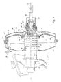
- FIG. 1 we can see a pneumatic brake booster type known with a longitudinal axis X comprising an envelope 1 formed by a first and a second shell 3 and 5, the shells 3 and 5 being crimped by their outer periphery.
- the shell 3 has a central orifice 4 extending towards the rear by a chimney 6 in which a pneumatic piston 17 is mounted in leaktight sliding, the shell 5 comprises a central orifice 8 receiving a master cylinder 10.
- the casing 1 defines a interior volume 7 divided in leaktight manner into a working chamber 9 and a vacuum chamber 11 by means of a skirt of substantially annular shape 13 likely to move along the X axis under a pressure difference.
- Skirt 13 has in its central part an orifice 15 in which is mounted in a sealed manner the pneumatic piston 17 comprising at a first end oriented towards the front a part of substantially conical shape 19 with taper oriented towards the rear and at a second end oriented towards the rear a sleeve 21.
- a three-way valve of the type known 23 disposed inside the pneumatic piston is controlled by a rod actuation 25 connected to a brake pedal (not shown). At rest, the valve three-way 23 connects the vacuum chamber 11 and the working chamber 9, and during a braking phase it connects the working chamber 9 and the high pressure outdoor environment.
- the braking action provided by the driver and the assistance provided by the servomotor is transmitted to at least one piston of the master cylinder via a push rod 27.
- a reaction disc 31 is disposed between a distributor plunger 29 forming part of the three-way valve 23 and receiving one end longitudinal front of the control rod 25 and a rear longitudinal end of the push rod 27 and transmitting the reaction from the braking circuit to the pedal brake.
- a return spring 33 is mounted in compression in the vacuum chamber between the pneumatic piston and the casing allowing the piston to return to the rest position tire and skirt.
- the vacuum chamber 11 is supplied with pneumatic fluid at low pressure by via a waterproof connector 35, the pneumatic fluid at low pressure from, for example, engine vacuum or a pneumatic pump (not shown).
- Sealing between the front vacuum chamber 11 and the rear working chamber 9 is made by means of a tube-shaped membrane 39 of short length relatively to its internal diameter and closed at one end by a bottom 41, the membrane 39 sealing between the skirt 13 and the casing 1 and between the skirt 13 and the pneumatic piston 17.
- the back 41 of the membrane 39 oriented towards the rear has a central orifice 43 receiving the front part 19 of the piston 17 on which the bottom 41 is fixed so waterproof by pinching a bead 45 bordering the periphery of the central orifice 43 between the skirt 13 and the periphery of the piston 17.
- the membrane 13 is also fixed tightly inside the envelope 13 by pinching an annular bead 47 bordering the front longitudinal end of the tube between the shells 3,5.
- the working chamber 9 is a variable pressure chamber; at rest she is in communication with the vacuum chamber 11 and is therefore subject to low pressure, during braking action the communication between the vacuum chamber 11 and the work 9 is interrupted and the communication between work chamber 9 and the external environment opens to allow entry of a pneumatic fluid to high pressure to enter the working chamber 9, this high pressure pneumatic fluid pressure can for example be air at atmospheric pressure.
- the difference of pressure between the vacuum chamber 11 and the working chamber 9 causes displacement of the skirt 13 and of the piston 17 in the direction of the push rod and then assists the action of driver braking on the brake pedal.
- the membrane When braking and moving the skirt along the X axis and the piston under the pressure difference between the working chamber and the vacuum chamber, the membrane, commonly known as a rolling membrane, takes place along the wall radially inner envelope 1.
- the pneumatic brake booster according to the present invention of axis Y comprises an envelope 101, a skirt 113 mounted with sealed sliding in the casing 101, a pneumatic piston 117 fixedly mounted in a central part of the skirt 113, said piston 117 being provided with a three-way valve capable of communication a low pressure chamber 111 arranged at the front of the skirt 113 and a variable pressure chamber 109 at the rear of the skirt 113.
- the seal between the chambers 111 and 109 is produced by first and second sealing means 157,156 disposed respectively between the skirt of the casing and between the skirt and the piston.
- the cover is formed by a cover 103 and a bowl 105 provided with a rim 153 for example made of pressed sheet steel of small thickness, the cover 103 fitting into the bowl 105 and comprising a sealing means 149, by example a seal mounted fixed in an annular groove 151 formed on the periphery radially external of the cover formed by folding the sheet, the seal 149 coming in waterproof application against the internal surface of the rim 153 of the bowl 105.
- the cover 103 has a central orifice 104 extending rearwards through a chimney 106 in which a rear part of the pneumatic piston 117, and the bowl 105 has a central orifice 108 receiving a master cylinder (not shown).
- the envelope 101 defines an interior volume 107 in which is slidably mounted along the Y axis, a skirt 113 of shape substantially annular comprising in its central part an orifice 115 in which is fixedly and tightly mounted a first end 119 oriented towards the front of the pneumatic piston 117 formed by a first sleeve force-fitted into the skirt 13.
- the orifice 115 is bordered by a gutter 155 whose outer surface surrounds the sleeve 119 of piston 117.
- the second first sealing means 156 for example a O-ring is arranged in tight contact against the outer surface of the gutter 155 in a groove 158 formed on the outer periphery of the sleeve 119 of the piston 117.
- the vacuum chamber 111 being in communication with a vacuum source by example a vacuum pump or the engine vacuum.
- the seal between the skirt 113 and the casing 101 is produced by the first sealing means 157 fixed relative to the skirt 113 and mounted movable and capable of slide on the inner surface of the flange 153 of the casing 101.
- the first sealing means 157 is formed by a portion of small tube length relative to its diameter, the diameter of the tube 157 being substantially equal the outside diameter of the skirt 113.
- a first longitudinal end 161 of the tube 157 facing forward is fixedly mounted at one end radially outer 163 of the skirt 113 by pinching this first end 161 of the tube 157 by means of an annular fold 165 oriented towards the actuating rod 125 and formed on the radially outer end of the skirt 113.
- a low cavity pressure 167 is provided between the fold 165 and the first longitudinal end 161 of the part of the tube 157, as well as sealing tabs 169 on the outer surface of tube 157 pinched in the fold 165, said tabs 169 being oriented in the direction opposite to that of the low pressure cavity 167.
- the tongues 169 are glued against the skirt 113 due to the pressure difference between the working chamber 109 and the low pressure chamber 111 increasing the seal between the skirt 113 and the tube 157.
- the tongues 169 come off the skirt 113 due to the balance of pressures between the vacuum chamber 111 and the working chamber 109 allowing a pneumatic fluid replenishment at low pressure in cavity 167, and allowing thus increasing the seal between the vacuum chamber 111 and the working chamber 109 during braking.
- first end 161 of the tube 157 is fixed from tightly to the skirt 113 in a manner other than by pinching, for example by hooking on the skirt, it will then be necessary to provide means for hooking on the skirt and on the tube 157 capable of cooperating with each other, or by gluing, it is no longer useful to provide the chamber at atmospheric pressure 172.
- the outer surface of the tube forms an annular lip 173 in contact substantially with tangentially against the internal surface of the rim 153 of the bowl 105.
- the application of the lip 173 on the internal surface of the rim 153 of the bowl 105 is increased during a braking phase by the difference in pressures prevailing between the vacuum chamber 111 and working chamber 109, in fact the lip 173 is "sucked" towards the vacuum chamber 111 and "sticks" to the internal surface 153 of the bowl 105.
- the lip 173 is of sufficient length to seal the two chambers 109,111 without risk of being placed between the radially external end of the skirt 113 and the flange 153.
- the tightness depends on the force of application of the annular seal 156 on the inner surface of the flange 153, which is for example a compressive force of the seal annular between the skirt and the flange 153.
- the sealing means 157 is made of elastic, flexible and waterproof material. air, for example rubber or sliding EPDM.
- the pneumatic piston 117 is formed from a part that is substantially of revolution. pierced with a longitudinal passage 179 passing through, receiving a three-way valve 123 from known type actuated by an actuating rod 123 connected to a brake pedal (not shown), the valve 123 putting the vacuum chamber 111 into communication with one another and the working chamber 109, and during a braking phase the working chamber 109 and the high pressure outdoor environment.
- the braking action provided by the driver and the assistance provided by the servomotor is transmitted to at least one piston of a master cylinder via a push rod 127.
- a reaction disc 131 is arranged between a distributor plunger 133 forming part of the three-way valve 123 and receiving one end longitudinal front of control rod 125 and rear longitudinal end of the push rod 127 and transmitting the reaction from the braking circuit to the brake.
- a return spring 133 is mounted in compression in the vacuum chamber, in the example shown, it is supported between a reinforcement piece 179 applied against the internal surface of the bowl 105 and the edges of a shaped piece 177 substantially of cap whose bottom cooperates with the front face of the pneumatic piston 117 and the edges are partially applied against the front face of the skirt 113.
- the driver depresses the brake pedal which moves the actuating rod 125. There is then closure of the communication between the chamber 105 and the working chamber 103 and opening of the communication between the working chamber 103 and the external environment at atmospheric pressure. Because the pressure difference which appears between the working chamber 103 and the chamber vacuum 105, the skirt 113 and the pneumatic piston 117 move in the direction of the push rod 127 along the Y axis.
- the outer end of the sealing means 157 capable of sliding tightly on the inner surface of the flange 153 of the casing 101 seals between the working chamber 109 and the front chamber 111 without interfering with the longitudinal movement of the skirt in the casing 101.
- a servomotor has indeed been produced comprising sealing means between the vacuum chamber and the simple and inexpensive working chamber, since the room sealing effecting the sealing between the inner surface of the casing and the skirt is made from a tube of elastic and airtight material, for example rubber or sliding EPDM, cut longitudinally to the desired length, and the seal between the skirt 113 and the pneumatic piston 117 is effected by means of a standard low cost O-ring. It is no longer necessary to carry out a molded membrane in the shape of a pot provided with beads bordering its ends.
- the assembly is simplified since the sealing means is only fixed on the skirt and simply pressing against the internal surface of the envelope.
- a pneumatic brake booster comprising a working chamber arranged at the front of the actuator and a vacuum disposed at the rear of the booster does not depart from the scope of the present invention.
- the present invention is particularly applicable to the automotive industry.
- the present invention applies mainly to the industry of braking for motor vehicles and especially for passenger cars.
Landscapes
- Engineering & Computer Science (AREA)
- Transportation (AREA)
- Mechanical Engineering (AREA)
- Braking Systems And Boosters (AREA)
- Braking Arrangements (AREA)
Applications Claiming Priority (2)
| Application Number | Priority Date | Filing Date | Title |
|---|---|---|---|
| FR0203583A FR2837452B1 (fr) | 2002-03-21 | 2002-03-21 | Servomoteur d'assistance pneumatique au freinage comportant des moyens d'etancheite ameliores |
| FR0203583 | 2002-03-21 |
Publications (2)
| Publication Number | Publication Date |
|---|---|
| EP1346894A1 true EP1346894A1 (de) | 2003-09-24 |
| EP1346894B1 EP1346894B1 (de) | 2004-10-13 |
Family
ID=27772266
Family Applications (1)
| Application Number | Title | Priority Date | Filing Date |
|---|---|---|---|
| EP03005808A Expired - Lifetime EP1346894B1 (de) | 2002-03-21 | 2003-03-14 | Pneumatischer Bremskraftverstärker mit verbesserter Dichtung |
Country Status (7)
| Country | Link |
|---|---|
| US (1) | US6928918B2 (de) |
| EP (1) | EP1346894B1 (de) |
| JP (1) | JP2004034963A (de) |
| AT (1) | ATE279341T1 (de) |
| DE (1) | DE60300084T2 (de) |
| ES (1) | ES2225803T3 (de) |
| FR (1) | FR2837452B1 (de) |
Cited By (1)
| Publication number | Priority date | Publication date | Assignee | Title |
|---|---|---|---|---|
| WO2007010031A1 (de) * | 2005-07-22 | 2007-01-25 | Continental Teves Ag & Co. Ohg | Pneumatischer bremskraftverstärker und membran dafür |
Families Citing this family (2)
| Publication number | Priority date | Publication date | Assignee | Title |
|---|---|---|---|---|
| US20080199595A1 (en) * | 2007-02-15 | 2008-08-21 | Mccormick & Company | Salt replacing composition, process for its preparation and food systems containing such composition |
| DE102015225832A1 (de) * | 2015-12-17 | 2017-06-22 | Continental Teves Ag & Co. Ohg | Pneumatischer Bremskraftverstärker mit einem metallbeschichteten Verstärkergehäuse |
Citations (3)
| Publication number | Priority date | Publication date | Assignee | Title |
|---|---|---|---|---|
| JPS58128950A (ja) * | 1982-01-26 | 1983-08-01 | Jidosha Kiki Co Ltd | ブレ−キ倍力装置 |
| US5320024A (en) * | 1989-04-22 | 1994-06-14 | Alfred Teves Gmbh | Vacuum brake force booster for automotive vehicles |
| FR2762568A1 (fr) * | 1997-04-28 | 1998-10-30 | Bosch Syst Freinage | Servomoteur pneumatique a chambre de pilotage |
Family Cites Families (4)
| Publication number | Priority date | Publication date | Assignee | Title |
|---|---|---|---|---|
| US3037487A (en) * | 1960-11-28 | 1962-06-05 | Gen Motors Corp | Brake booster valve means |
| US4270353A (en) * | 1977-10-20 | 1981-06-02 | Girling Limited | Servo boosters for vehicle brake systems |
| JPS5842058B2 (ja) * | 1979-07-11 | 1983-09-16 | 自動車機器株式会社 | ブレ−キ倍力装置 |
| DE3024967A1 (de) * | 1980-07-02 | 1982-01-28 | Alfred Teves Gmbh, 6000 Frankfurt | Mechanisch steuerbarer kraftverstaerker, insbesondere fuer eine hydraulische bremsanlage |
-
2002
- 2002-03-21 FR FR0203583A patent/FR2837452B1/fr not_active Expired - Fee Related
-
2003
- 2003-03-14 ES ES03005808T patent/ES2225803T3/es not_active Expired - Lifetime
- 2003-03-14 EP EP03005808A patent/EP1346894B1/de not_active Expired - Lifetime
- 2003-03-14 AT AT03005808T patent/ATE279341T1/de not_active IP Right Cessation
- 2003-03-14 DE DE60300084T patent/DE60300084T2/de not_active Expired - Lifetime
- 2003-03-20 JP JP2003079162A patent/JP2004034963A/ja not_active Withdrawn
- 2003-03-21 US US10/394,468 patent/US6928918B2/en not_active Expired - Fee Related
Patent Citations (3)
| Publication number | Priority date | Publication date | Assignee | Title |
|---|---|---|---|---|
| JPS58128950A (ja) * | 1982-01-26 | 1983-08-01 | Jidosha Kiki Co Ltd | ブレ−キ倍力装置 |
| US5320024A (en) * | 1989-04-22 | 1994-06-14 | Alfred Teves Gmbh | Vacuum brake force booster for automotive vehicles |
| FR2762568A1 (fr) * | 1997-04-28 | 1998-10-30 | Bosch Syst Freinage | Servomoteur pneumatique a chambre de pilotage |
Non-Patent Citations (1)
| Title |
|---|
| PATENT ABSTRACTS OF JAPAN vol. 007, no. 244 (M - 252) 28 October 1983 (1983-10-28) * |
Cited By (3)
| Publication number | Priority date | Publication date | Assignee | Title |
|---|---|---|---|---|
| WO2007010031A1 (de) * | 2005-07-22 | 2007-01-25 | Continental Teves Ag & Co. Ohg | Pneumatischer bremskraftverstärker und membran dafür |
| US7938056B2 (en) | 2005-07-22 | 2011-05-10 | Continental Teves Ag & Co. Ohg | Pneumatic servobrake and diaphragm therefor |
| CN101228055B (zh) * | 2005-07-22 | 2011-06-08 | 大陆-特韦斯贸易合伙股份公司及两合公司 | 气动制动助力器及其膜片 |
Also Published As
| Publication number | Publication date |
|---|---|
| ES2225803T3 (es) | 2005-03-16 |
| FR2837452B1 (fr) | 2004-07-02 |
| FR2837452A1 (fr) | 2003-09-26 |
| EP1346894B1 (de) | 2004-10-13 |
| JP2004034963A (ja) | 2004-02-05 |
| DE60300084T2 (de) | 2005-10-20 |
| DE60300084D1 (de) | 2004-11-18 |
| ATE279341T1 (de) | 2004-10-15 |
| US6928918B2 (en) | 2005-08-16 |
| US20030177898A1 (en) | 2003-09-25 |
Similar Documents
| Publication | Publication Date | Title |
|---|---|---|
| EP1360101B1 (de) | Reaktionsvorrichtung für bremskraftverstärker | |
| FR2489437A1 (fr) | Amplificateur de force commande mecaniquement, notamment pour installations de freinage hydraulique | |
| EP1346894B1 (de) | Pneumatischer Bremskraftverstärker mit verbesserter Dichtung | |
| FR2837453A1 (fr) | Servomoteur d'assistance pneumatique au freinage comportant des moyens d'etancheite ameliores | |
| FR2724356A1 (fr) | Servomoteur pneumatique d'assistance au freinage | |
| EP0999964B1 (de) | Pneumatischer kraftverstärker mit steuerkammer | |
| EP0877689B1 (de) | Bremskraftverstärker mit verbessertem ventil | |
| EP1688332B1 (de) | Pneumatischer Kraftverstärker mit versetzten Ventilsitzen, die von zwei ineinander gleitenden Hülsen getragen werden | |
| EP1511662A1 (de) | Druckluftventil für bremsanlagen | |
| EP0796190B1 (de) | Pneumatischer bremskraftverstärker | |
| EP1628866B1 (de) | Pneumatischer servomotor mit einem auf den membranteller aufgespritztes membran | |
| FR2938626A1 (fr) | Ensemble de raccordement etanche | |
| EP0448417A1 (de) | Bremskraftverstärker | |
| EP0319359B1 (de) | Bremskraftverstärker | |
| EP1439991B1 (de) | Kolbeneinheit mit dichtung, für fahrzeugbremskraftverstärker einer fahrzeugbremsanlage, und bremskraftverstärker der eine solche kolbeneinheit umfasst | |
| EP1361125B1 (de) | Bremskraftverstärker mit einer an der Aussenseite angebrachten Dichtung | |
| EP0802870B1 (de) | Pneumatischer bremskraftverstärker mit elastischem ventil | |
| WO2002102634A2 (fr) | Servomoteur d'assistance pneumatique au freinage a hauteur de saut variable. | |
| FR2939862A1 (fr) | Dispositif de raccordement etanche d'un embout sur une paroi d'une structure etanche | |
| EP0368701B1 (de) | Hydraulische Servobremsanlage und Bremskraftverstärker und Regelventil für eine solche Anlage | |
| EP1437280B1 (de) | Pneumatischer Servo mit reduzierter Ausgleichdauer | |
| EP0681538B1 (de) | Pneumatischer servomotor | |
| FR2939865A1 (fr) | Ensemble de raccordement etanche entre une structure et un embout de raccord | |
| FR2872762A1 (fr) | Disque de reaction possedant une surepaisseur d'etancheite pour servomoteur d'assistance de freinage | |
| FR2920379A1 (fr) | Boitier de servomoteur d'assistance au freinage |
Legal Events
| Date | Code | Title | Description |
|---|---|---|---|
| PUAI | Public reference made under article 153(3) epc to a published international application that has entered the european phase |
Free format text: ORIGINAL CODE: 0009012 |
|
| AK | Designated contracting states |
Kind code of ref document: A1 Designated state(s): AT BE BG CH CY CZ DE DK EE ES FI FR GB GR HU IE IT LI LU MC NL PT RO SE SI SK TR |
|
| AX | Request for extension of the european patent |
Extension state: AL LT LV MK |
|
| GRAP | Despatch of communication of intention to grant a patent |
Free format text: ORIGINAL CODE: EPIDOSNIGR1 |
|
| 17P | Request for examination filed |
Effective date: 20040324 |
|
| AKX | Designation fees paid |
Designated state(s): AT BE BG CH CY CZ DE DK EE ES FI FR GB GR HU IE IT LI LU MC NL PT RO SE SI SK TR |
|
| GRAS | Grant fee paid |
Free format text: ORIGINAL CODE: EPIDOSNIGR3 |
|
| GRAA | (expected) grant |
Free format text: ORIGINAL CODE: 0009210 |
|
| AK | Designated contracting states |
Kind code of ref document: B1 Designated state(s): AT BE BG CH CY CZ DE DK EE ES FI FR GB GR HU IE IT LI LU MC NL PT RO SE SI SK TR |
|
| PG25 | Lapsed in a contracting state [announced via postgrant information from national office to epo] |
Ref country code: EE Free format text: LAPSE BECAUSE OF FAILURE TO SUBMIT A TRANSLATION OF THE DESCRIPTION OR TO PAY THE FEE WITHIN THE PRESCRIBED TIME-LIMIT Effective date: 20041013 Ref country code: NL Free format text: LAPSE BECAUSE OF FAILURE TO SUBMIT A TRANSLATION OF THE DESCRIPTION OR TO PAY THE FEE WITHIN THE PRESCRIBED TIME-LIMIT Effective date: 20041013 Ref country code: BG Free format text: LAPSE BECAUSE OF FAILURE TO SUBMIT A TRANSLATION OF THE DESCRIPTION OR TO PAY THE FEE WITHIN THE PRESCRIBED TIME-LIMIT Effective date: 20041013 Ref country code: CZ Free format text: LAPSE BECAUSE OF FAILURE TO SUBMIT A TRANSLATION OF THE DESCRIPTION OR TO PAY THE FEE WITHIN THE PRESCRIBED TIME-LIMIT Effective date: 20041013 Ref country code: RO Free format text: LAPSE BECAUSE OF FAILURE TO SUBMIT A TRANSLATION OF THE DESCRIPTION OR TO PAY THE FEE WITHIN THE PRESCRIBED TIME-LIMIT Effective date: 20041013 Ref country code: SI Free format text: LAPSE BECAUSE OF FAILURE TO SUBMIT A TRANSLATION OF THE DESCRIPTION OR TO PAY THE FEE WITHIN THE PRESCRIBED TIME-LIMIT Effective date: 20041013 Ref country code: SK Free format text: LAPSE BECAUSE OF FAILURE TO SUBMIT A TRANSLATION OF THE DESCRIPTION OR TO PAY THE FEE WITHIN THE PRESCRIBED TIME-LIMIT Effective date: 20041013 Ref country code: AT Free format text: LAPSE BECAUSE OF FAILURE TO SUBMIT A TRANSLATION OF THE DESCRIPTION OR TO PAY THE FEE WITHIN THE PRESCRIBED TIME-LIMIT Effective date: 20041013 Ref country code: FI Free format text: LAPSE BECAUSE OF FAILURE TO SUBMIT A TRANSLATION OF THE DESCRIPTION OR TO PAY THE FEE WITHIN THE PRESCRIBED TIME-LIMIT Effective date: 20041013 Ref country code: IE Free format text: LAPSE BECAUSE OF FAILURE TO SUBMIT A TRANSLATION OF THE DESCRIPTION OR TO PAY THE FEE WITHIN THE PRESCRIBED TIME-LIMIT Effective date: 20041013 |
|
| REG | Reference to a national code |
Ref country code: GB Ref legal event code: FG4D Free format text: NOT ENGLISH |
|
| REG | Reference to a national code |
Ref country code: CH Ref legal event code: EP |
|
| REG | Reference to a national code |
Ref country code: IE Ref legal event code: FG4D Free format text: FRENCH |
|
| REF | Corresponds to: |
Ref document number: 60300084 Country of ref document: DE Date of ref document: 20041118 Kind code of ref document: P |
|
| GBT | Gb: translation of ep patent filed (gb section 77(6)(a)/1977) |
Effective date: 20041201 |
|
| PG25 | Lapsed in a contracting state [announced via postgrant information from national office to epo] |
Ref country code: DK Free format text: LAPSE BECAUSE OF FAILURE TO SUBMIT A TRANSLATION OF THE DESCRIPTION OR TO PAY THE FEE WITHIN THE PRESCRIBED TIME-LIMIT Effective date: 20050113 Ref country code: SE Free format text: LAPSE BECAUSE OF FAILURE TO SUBMIT A TRANSLATION OF THE DESCRIPTION OR TO PAY THE FEE WITHIN THE PRESCRIBED TIME-LIMIT Effective date: 20050113 Ref country code: GR Free format text: LAPSE BECAUSE OF FAILURE TO SUBMIT A TRANSLATION OF THE DESCRIPTION OR TO PAY THE FEE WITHIN THE PRESCRIBED TIME-LIMIT Effective date: 20050113 |
|
| PG25 | Lapsed in a contracting state [announced via postgrant information from national office to epo] |
Ref country code: HU Free format text: LAPSE BECAUSE OF FAILURE TO SUBMIT A TRANSLATION OF THE DESCRIPTION OR TO PAY THE FEE WITHIN THE PRESCRIBED TIME-LIMIT Effective date: 20050114 |
|
| PG25 | Lapsed in a contracting state [announced via postgrant information from national office to epo] |
Ref country code: LU Free format text: LAPSE BECAUSE OF NON-PAYMENT OF DUE FEES Effective date: 20050314 Ref country code: CY Free format text: LAPSE BECAUSE OF FAILURE TO SUBMIT A TRANSLATION OF THE DESCRIPTION OR TO PAY THE FEE WITHIN THE PRESCRIBED TIME-LIMIT Effective date: 20050314 |
|
| REG | Reference to a national code |
Ref country code: ES Ref legal event code: FG2A Ref document number: 2225803 Country of ref document: ES Kind code of ref document: T3 |
|
| PG25 | Lapsed in a contracting state [announced via postgrant information from national office to epo] |
Ref country code: BE Free format text: LAPSE BECAUSE OF NON-PAYMENT OF DUE FEES Effective date: 20050331 Ref country code: MC Free format text: LAPSE BECAUSE OF NON-PAYMENT OF DUE FEES Effective date: 20050331 |
|
| NLV1 | Nl: lapsed or annulled due to failure to fulfill the requirements of art. 29p and 29m of the patents act | ||
| REG | Reference to a national code |
Ref country code: IE Ref legal event code: FD4D |
|
| PLBE | No opposition filed within time limit |
Free format text: ORIGINAL CODE: 0009261 |
|
| STAA | Information on the status of an ep patent application or granted ep patent |
Free format text: STATUS: NO OPPOSITION FILED WITHIN TIME LIMIT |
|
| BERE | Be: lapsed |
Owner name: ROBERT BOSCH G.M.B.H. Effective date: 20050331 |
|
| 26N | No opposition filed |
Effective date: 20050714 |
|
| REG | Reference to a national code |
Ref country code: CH Ref legal event code: PL |
|
| BERE | Be: lapsed |
Owner name: ROBERT *BOSCH G.M.B.H. Effective date: 20050331 |
|
| PG25 | Lapsed in a contracting state [announced via postgrant information from national office to epo] |
Ref country code: PT Free format text: LAPSE BECAUSE OF NON-PAYMENT OF DUE FEES Effective date: 20050313 |
|
| PG25 | Lapsed in a contracting state [announced via postgrant information from national office to epo] |
Ref country code: CH Free format text: LAPSE BECAUSE OF NON-PAYMENT OF DUE FEES Effective date: 20070331 Ref country code: LI Free format text: LAPSE BECAUSE OF NON-PAYMENT OF DUE FEES Effective date: 20070331 |
|
| PGFP | Annual fee paid to national office [announced via postgrant information from national office to epo] |
Ref country code: FR Payment date: 20140319 Year of fee payment: 12 |
|
| PGFP | Annual fee paid to national office [announced via postgrant information from national office to epo] |
Ref country code: DE Payment date: 20150521 Year of fee payment: 13 |
|
| REG | Reference to a national code |
Ref country code: FR Ref legal event code: ST Effective date: 20151130 |
|
| PG25 | Lapsed in a contracting state [announced via postgrant information from national office to epo] |
Ref country code: FR Free format text: LAPSE BECAUSE OF NON-PAYMENT OF DUE FEES Effective date: 20150331 |
|
| PGFP | Annual fee paid to national office [announced via postgrant information from national office to epo] |
Ref country code: ES Payment date: 20160322 Year of fee payment: 14 Ref country code: TR Payment date: 20160301 Year of fee payment: 14 |
|
| PGFP | Annual fee paid to national office [announced via postgrant information from national office to epo] |
Ref country code: GB Payment date: 20160322 Year of fee payment: 14 |
|
| PGFP | Annual fee paid to national office [announced via postgrant information from national office to epo] |
Ref country code: IT Payment date: 20160318 Year of fee payment: 14 |
|
| REG | Reference to a national code |
Ref country code: DE Ref legal event code: R119 Ref document number: 60300084 Country of ref document: DE |
|
| PG25 | Lapsed in a contracting state [announced via postgrant information from national office to epo] |
Ref country code: DE Free format text: LAPSE BECAUSE OF NON-PAYMENT OF DUE FEES Effective date: 20161001 |
|
| GBPC | Gb: european patent ceased through non-payment of renewal fee |
Effective date: 20170314 |
|
| PG25 | Lapsed in a contracting state [announced via postgrant information from national office to epo] |
Ref country code: GB Free format text: LAPSE BECAUSE OF NON-PAYMENT OF DUE FEES Effective date: 20170314 Ref country code: IT Free format text: LAPSE BECAUSE OF NON-PAYMENT OF DUE FEES Effective date: 20170314 |
|
| REG | Reference to a national code |
Ref country code: ES Ref legal event code: FD2A Effective date: 20180706 |
|
| PG25 | Lapsed in a contracting state [announced via postgrant information from national office to epo] |
Ref country code: ES Free format text: LAPSE BECAUSE OF NON-PAYMENT OF DUE FEES Effective date: 20170315 |
|
| PG25 | Lapsed in a contracting state [announced via postgrant information from national office to epo] |
Ref country code: TR Free format text: LAPSE BECAUSE OF NON-PAYMENT OF DUE FEES Effective date: 20170314 |