EP1347149A2 - Porte enroulable - Google Patents
Porte enroulable Download PDFInfo
- Publication number
- EP1347149A2 EP1347149A2 EP03006238A EP03006238A EP1347149A2 EP 1347149 A2 EP1347149 A2 EP 1347149A2 EP 03006238 A EP03006238 A EP 03006238A EP 03006238 A EP03006238 A EP 03006238A EP 1347149 A2 EP1347149 A2 EP 1347149A2
- Authority
- EP
- European Patent Office
- Prior art keywords
- closing
- stabilizing
- guide
- closing element
- closed position
- Prior art date
- Legal status (The legal status is an assumption and is not a legal conclusion. Google has not performed a legal analysis and makes no representation as to the accuracy of the status listed.)
- Withdrawn
Links
- 230000033001 locomotion Effects 0.000 claims abstract description 51
- 230000000087 stabilizing effect Effects 0.000 claims description 40
- 238000004804 winding Methods 0.000 claims description 24
- 230000008878 coupling Effects 0.000 claims description 7
- 238000010168 coupling process Methods 0.000 claims description 7
- 238000005859 coupling reaction Methods 0.000 claims description 7
- 230000005484 gravity Effects 0.000 claims description 2
- 239000000463 material Substances 0.000 claims description 2
- 230000006378 damage Effects 0.000 description 34
- 208000027418 Wounds and injury Diseases 0.000 description 15
- 208000014674 injury Diseases 0.000 description 12
- 239000004576 sand Substances 0.000 description 4
- 230000006641 stabilisation Effects 0.000 description 4
- 238000011105 stabilization Methods 0.000 description 4
- 230000008901 benefit Effects 0.000 description 3
- 230000009467 reduction Effects 0.000 description 3
- 230000005540 biological transmission Effects 0.000 description 2
- 230000000694 effects Effects 0.000 description 2
- 230000008719 thickening Effects 0.000 description 2
- 230000004308 accommodation Effects 0.000 description 1
- 230000004888 barrier function Effects 0.000 description 1
- 230000002688 persistence Effects 0.000 description 1
- 239000012858 resilient material Substances 0.000 description 1
- 238000005096 rolling process Methods 0.000 description 1
- 230000008054 signal transmission Effects 0.000 description 1
- 230000002459 sustained effect Effects 0.000 description 1
- 230000007704 transition Effects 0.000 description 1
Images

Classifications
-
- E—FIXED CONSTRUCTIONS
- E06—DOORS, WINDOWS, SHUTTERS, OR ROLLER BLINDS IN GENERAL; LADDERS
- E06B—FIXED OR MOVABLE CLOSURES FOR OPENINGS IN BUILDINGS, VEHICLES, FENCES OR LIKE ENCLOSURES IN GENERAL, e.g. DOORS, WINDOWS, BLINDS, GATES
- E06B9/00—Screening or protective devices for wall or similar openings, with or without operating or securing mechanisms; Closures of similar construction
- E06B9/56—Operating, guiding or securing devices or arrangements for roll-type closures; Spring drums; Tape drums; Counterweighting arrangements therefor
- E06B9/62—Counterweighting arrangements
-
- E—FIXED CONSTRUCTIONS
- E06—DOORS, WINDOWS, SHUTTERS, OR ROLLER BLINDS IN GENERAL; LADDERS
- E06B—FIXED OR MOVABLE CLOSURES FOR OPENINGS IN BUILDINGS, VEHICLES, FENCES OR LIKE ENCLOSURES IN GENERAL, e.g. DOORS, WINDOWS, BLINDS, GATES
- E06B9/00—Screening or protective devices for wall or similar openings, with or without operating or securing mechanisms; Closures of similar construction
- E06B9/56—Operating, guiding or securing devices or arrangements for roll-type closures; Spring drums; Tape drums; Counterweighting arrangements therefor
- E06B9/80—Safety measures against dropping or unauthorised opening; Braking or immobilising devices; Devices for limiting unrolling
Definitions
- the invention relates to a device for closing a wall opening, in particular a roller shutter, with a closing element that is between a closed position, in the it is arranged essentially in a vertical plane, and movable in an open position is, and a weight compensation device supporting an opening movement of the closing element.
- the closing element can be in the transition from the closed position in the opening position is wound up on a winding shaft arranged above the hall entrance become.
- the closing element in the form of a so-called. Lamellar armor with a variety of. perpendicular to the direction of movement of the Closing element extending joint axes articulated slats be educated.
- the closing element also in the form of a web-shaped curtain, for example made of PVC.
- a weight compensation device is generally used for the opening movement, with the closing element from the closed position up towards the Open position is pushed.
- a weight compensation device can in The course of the closing movement of the closing element absorb the energy released is later available to support the opening movement.
- Such weight balancing devices can be in the form of spring arrangements, in particular tension and / or torsion spring arrangements can be realized, which in the course of the closing movement excited and relaxed again in the course of the opening movement.
- the weight compensation devices can also have weights, which is raised in the course of the closing movement of the closing element and in Course of the opening movement can be lowered again.
- the weight compensation device When dimensioning the weight compensation device must be in particular Roller shutters with a closing element in the form of a sheet-shaped curtain be that at the beginning of the closing movement a considerable breakaway torque the drive must be overcome, while afterwards only a comparatively small Moment is required to continue the opening movement. This breakaway moment is typically 15 Nm or more, while usually to continue the movement a torque of 2 to 3 Nm is required. Accordingly, the weight balancer be dimensioned so that they have a correspondingly high breakaway torque provides. In the course of the opening movement, the closing element accelerates according to the breakaway torque and must be reached when the opening position is reached are braked accordingly to damage the drive, the To avoid closing element and / or the winding shaft. Alternatively, the above Elements are also dimensioned so that damage even when abruptly stopping the opening movement does not occur. The two described above However, possibilities require a high level of design effort to avoid Damage to the roller door.
- the object of the invention to provide a structurally simple device of the type described in the introduction, with which on the one hand a sufficiently high breakaway torque is made available and on the other hand damage to the device elements when they are reached the open position is reliably prevented.
- this object is achieved by developing the known devices solved, which is essentially characterized in that the weight compensation device has at least one compensating element with which the closing element is pushed into the open position in the closed position and that the opening movement brakes again when reaching the open position.
- the weight compensation device not only used to overcome the breakaway torque of the drive, but by corresponding coupling to the closing element also for braking the same at Reaching the open position. This means damage without additional design effort the closing element, the winding shaft and / or other device elements reliably prevented.
- the further development according to the invention becomes more well known Locking device used with particular advantage in rolling gates, where the In the open position, the closing element is at least partially wound on a winding shaft is, with particular advantages if the closing element at least is partially realized in the form of a web-shaped curtain.
- the compensation element is structurally particularly simple via a coupling arrangement weight coupled to the winding shaft and movable along a predetermined path exhibit. If this weight by appropriate coupling to the winding shaft in the The course of the opening movement is first lowered and then raised again a support by the weight in the closed position of the closing element a deceleration of the opening movement and in the further course of the opening movement.
- This has the further advantage that the braking of the Closing element in the course of the opening movement of the weight compensation device Energy absorbed to support the closing movement, i.e. to overcome of the persistence of the closing element on the winding shaft at the beginning of Closing motion is available.
- the weight compensation device further developed according to the invention braked. The energy absorbed by the compensating element is then available Overcoming the breakaway torque of the drive again during an opening movement Available.
- the compensation element is expediently coupled to the winding shaft via a traction device, which on the one hand is preferably in the form of a weight Realize compensating element and on the other hand via a rotationally fixed with the winding shaft connected disc is coupled to the winding shaft.
- This traction device can, for example be realized in the form of a belt.
- the Belt In the course of the opening movement, the Belt first unwound from the belt pulley so that the weight is reduced. in the Further course of the opening movement, the belt is then again on the belt pulley wound, so as to slow down the opening movement when reaching the opening position to effect.
- the weight compensation device has at least one more, possibly via a further coupling arrangement compensating element coupled to the winding shaft, with which the opening movement of the closing element is supported.
- This additional compensation element can be in Conventional form can be realized without it to slow down the movement of the shooting element contributes when reaching the open position.
- two compensating elements on the opposite one another provided lateral edges of the closing element are two compensating elements on the opposite one another provided lateral edges of the closing element.
- This guide element is expediently in the region of the lateral edge of the closing element arranged in the closed position.
- the guide element can also be used for guidance be designed for the movement of the closing element. You can do this within the guide elements Thickening should be provided so that an easy pulling out of the Closing element or curtain is prevented from the guide elements. Furthermore can be partially applied to the side of the curtain thickening, which also a rapid pulling out of the curtain, e.g. B. prevent at low wind load, if exceeded a permissible load, however, leave the guide elements.
- the stabilizing element When using roller shutters with a closing element in the form of a sheet Curtain is usually a stabilizing element on the lower edge of the web-shaped curtain intended. With this stabilizing element, the shape of the stabilized the lower edge of the web-shaped curtain in order to achieve a defined conclusion ensure the closing element in the closed position. On the other hand, the stabilizing element serves to support the closing movement. With conventional roller shutters the stabilizing element in the form of a at the bottom of the web-shaped curtain attached rod realized.
- roller shutters are shaped with a closing element of a web-shaped curtain is used in particular when it needs quick opening and closing movements arrives.
- the attachment of the stabilizing element at the lower edge of the web-shaped curtain in the course of Closing movement a considerable risk of injury if the stabilizing element in the The course of the closing movement strikes a person standing in the driveway.
- Can also through the stabilizing elements of conventional roller shutters in the course of the closing movement objects are also damaged.
- conventional Stabilizing elements also damage the curtain itself and / or the Guide the movement of the curtain used guide elements occur when a Vehicle hits the curtain in the closed position.
- the stabilizing element usually realized in the form of a rigid rod through into one formed by folding the bottom edge of the curtain onto itself Loop to replace filled sand.
- the invention has for its object to provide a roller shutter, with the one hand a high level of operational reliability with a view to obtaining a reliable degree is ensured in the closed position and on the other hand the risk of damage and / or injuries to objects or people in the driveway, and the risk of damage to the curtain and / or the guide elements is reduced.
- this object is achieved by a Further development of known roller shutters, which is essentially characterized by that the stabilizing element is elastically deformable.
- the Stabilizing element is elastically deformable.
- the stabilizing element a spring element, in particular a one parallel to the lower edge of the web-shaped curtain extending spiral axis has a helical circumferential spring element.
- a spring element in particular a one parallel to the lower edge of the web-shaped curtain extending spiral axis has a helical circumferential spring element.
- the stabilizing element of the roller shutter according to the invention can be received in a loop formed at the lower edge of the web-shaped curtain be, where it has proven to be particularly useful if the the lower edge of the web-shaped curtain folded back on itself to form the loop is.
- At least one with the guide element on at least one lateral edge of the closing element cooperating guide member can be arranged. If by impact of an object or vehicle on the closing element in the closed position Guide member is released from the guide element, reliable guidance of the Movement of the closing element can be ensured if at the upper edge of the guide element an inlet arrangement is arranged with which the guide member at a Closing movement of the closing element can be inserted automatically into the guide element is.
- the stabilizing element should also continue a reliable stabilization of the closing element in the closed position Wind loads and the like can be achieved.
- the invention will both significantly reduce the risk of damage or injuries to objects or people in the driveway, as well achieved the desired stabilization function by executing the stabilization element in this way is that the deformation of the stabilizing element in one of the closing direction opposing restoring force is less than that a deformation of the closing element in a direction transverse thereto, in particular approximately vertically restoring force counteracting the closing element in the direction running in the closed position. Due to the low restoring force when deforming in a direction opposite to the closing direction Direction will be a satisfactory reduction in the risk of damage or injuries, while due to the higher restoring force in one transverse direction ensures a good stabilization function in this direction becomes.
- the stabilizing element can at least a spring element with asymmetrical, esp. oval, elliptical or rectangular Cross-section in a perpendicular to the lower edge of the closing element Have section plane, the spring element in a perpendicular to the closing element has a greater thickness in the direction extending in the closed position than in a direction running in the closing direction. Additionally or alternatively, the stabilizing element at least two in one perpendicular to the closing element in the closing direction have spring elements arranged next to one another in order to to achieve a particularly high restoring force in this direction.
- An elastically deformable stabilizing element can be structurally particularly simple can be realized in the form of a spring bar.
- roller shutters there is a risk of injury and / or damage of objects or people in the driveway and the risk damage to the roller shutter itself by providing an elastically deformable Stabilizing element and / or the special guidance of the Closing element reduced.
- a further reduction in the risk of damage and / or injury can be achieved if the closing element one to switch off and / or causing a reversal of direction coupled to the closing element Drive device operable safety device is assigned, so overloads the drive device and sustained application of force from the entrance Objects or people are reliably excluded.
- the securing device has a transmitting element operable to emit wirelessly transmissible signals and a receiving element operable to receive the wirelessly transmitted signals on, wherein the transmitting element and / or the receiving element on, preferably in the stabilizing element is arranged.
- the securing device has a light barrier with a stabilizing element used spring element used transmission element and one also received element used in the spring element.
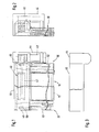
- the roller shutter shown in Fig. 1 comprises a web-shaped curtain 10, a first Guide element 20, a second guide element 30, one above that with the curtain 10 arranged winding shaft 40 to be closed driveway and a drive 42, with which the winding shaft 40 is driven to rotate.
- a support body 41 is arranged, on which the web-shaped curtain 10 can be wound.
- the winding shaft is received in a bearing 48.
- a belt pulley 50 is fastened in a rotationally fixed manner.
- the belt pulley 50 is connected to a belt 52, which on the other hand has a weight (not shown) is connected.
- a belt pulley 60 rotatably attached, which is connected to a belt 62.
- the belt 62 is on the other hand also connected to a weight (not shown).
- the weight coupled to the belt 52 When unwinding of the curtain 10 from the support body 41, the weight coupled to the belt 52 is raised, so that this weight supports an opening movement of the curtain. That on the belt 62 is coupled weight when unrolling the curtain 10 from the support body 41st first slightly lowered and then also raised. This will trigger the closing movement of the curtain 10 facilitated.
- the belt 62 coupled weight the breakaway torque of the drive during an opening movement of the curtain 10 are overcome, while the coupled to the belt 62 Weight slows down the movement of the curtain 10 when the opening position is reached.
- the motor 42 is of a motor housing 44 covered, while the winding shaft 40 by a winding shaft housing 46 is covered.
- the closing element 10 realized in the form of a web-shaped curtain is folded back on itself at its lower edge to form a loop 12.
- the loop 12 is realized in the form of a helical circumferential spring element Stabilizing element added.
- this guide element 20 comprises one Guide plates enclosing space 120 and delimiting a guide slot 26.
- the edges of the guide plates 22 and 24 facing the guide slot 26 are for Avoiding damage to the web-shaped guided through the guide slot 26 Curtain covered with a plastic layer.
- a space 122 is formed, which is used for guidance of the weight fixed on the belt 52.
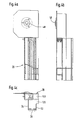
- the drive-side guide element 30 is shown.
- 5a shows a front view of this guide element
- Fig. 5b is a side view of this guide element
- FIG. 5c shows a horizontal sectional illustration of the guide element.
- the drive-side guide element 30 also comprises two enclosing a cavity 130 Guide plates 32 and 34 which delimit a guide slot 36. This too The guide element are the edges of the guide plates facing the guide slot 36 32 and 34 to avoid damage to the through the guide slot 36 guided curtain covered by a plastic layer.
- a bracket 230 is provided on the edge of the guide element 30, on which the motor 42 can be attached. For this purpose, there are a total of four mounting holes in the console 230 232 is provided.
- roller shutters according to the invention are also contemplated which instead of a spring element, a rod made of an elastically deformable plastic is used to form the stabilizing element.
- the weight compensation device Roller shutters according to the invention also realized in the form of spring arrangements his. In this case, the braking effect of the weight compensation device be reached by suitable deflection means when reaching the open position.
Landscapes
- Engineering & Computer Science (AREA)
- Structural Engineering (AREA)
- Architecture (AREA)
- Civil Engineering (AREA)
- Operating, Guiding And Securing Of Roll- Type Closing Members (AREA)
Priority Applications (17)
| Application Number | Priority Date | Filing Date | Title |
|---|---|---|---|
| DE20305922U DE20305922U1 (de) | 2003-03-20 | 2003-04-11 | Rolltor |
| US10/550,171 US20060225850A1 (en) | 2003-03-20 | 2003-06-01 | Rolling door |
| HRP20050684AA HRP20050684B1 (hr) | 2003-03-20 | 2003-06-13 | Vrata koja se namataju |
| CNA038261936A CN1759225A (zh) | 2003-03-20 | 2003-06-13 | 卷帘门 |
| YUP-2005/0710A RS50383B (sr) | 2003-03-20 | 2003-06-13 | Rolo-vrata |
| EA200501106A EA007212B1 (ru) | 2003-03-20 | 2003-06-13 | Жалюзийные ворота |
| DE50304906T DE50304906D1 (de) | 2003-03-20 | 2003-06-13 | Rolltor |
| AU2003246432A AU2003246432B2 (en) | 2003-03-20 | 2003-06-13 | Rolling door |
| AT03816503T ATE338192T1 (de) | 2003-03-20 | 2003-06-13 | Rolltor |
| EP03816503A EP1604091B2 (fr) | 2003-03-20 | 2003-06-13 | Porte roulante |
| JP2004570033A JP4535325B2 (ja) | 2003-03-20 | 2003-06-13 | シャッター |
| DK03816503T DK1604091T4 (da) | 2003-03-20 | 2003-06-13 | Rulleport |
| PCT/EP2003/006261 WO2004088080A1 (fr) | 2003-03-20 | 2003-06-13 | Porte roulante |
| PT03816503T PT1604091E (pt) | 2003-03-20 | 2003-06-13 | Portão corrediço |
| PL377302A PL207889B1 (pl) | 2003-03-20 | 2003-06-13 | Brama roletowa |
| UAA200507239A UA84860C2 (en) | 2003-03-20 | 2003-06-13 | Rolling door |
| ES03816503T ES2270180T5 (es) | 2003-03-20 | 2003-06-13 | Puerta arrollable. |
Applications Claiming Priority (2)
| Application Number | Priority Date | Filing Date | Title |
|---|---|---|---|
| DE20204637U DE20204637U1 (de) | 2002-03-22 | 2002-03-22 | Rolltor |
| DE20204637U | 2002-03-22 |
Publications (2)
| Publication Number | Publication Date |
|---|---|
| EP1347149A2 true EP1347149A2 (fr) | 2003-09-24 |
| EP1347149A3 EP1347149A3 (fr) | 2011-12-14 |
Family
ID=7969295
Family Applications (1)
| Application Number | Title | Priority Date | Filing Date |
|---|---|---|---|
| EP03006238A Withdrawn EP1347149A3 (fr) | 2002-03-22 | 2003-03-20 | Porte enroulable |
Country Status (2)
| Country | Link |
|---|---|
| EP (1) | EP1347149A3 (fr) |
| DE (1) | DE20204637U1 (fr) |
Families Citing this family (2)
| Publication number | Priority date | Publication date | Assignee | Title |
|---|---|---|---|---|
| DE20305922U1 (de) | 2003-03-20 | 2003-06-12 | Adolf Seuster GmbH & Co. KG, 58513 Lüdenscheid | Rolltor |
| DE102009056359B4 (de) * | 2009-11-30 | 2013-04-04 | Hörmann KG Amshausen | Drehwellenanordnung für ein Tor, insbesondere für ein Rolltor, ein Verfahren zu deren Herstellung und ein Tor |
Family Cites Families (11)
| Publication number | Priority date | Publication date | Assignee | Title |
|---|---|---|---|---|
| DE840364C (de) | 1950-10-10 | 1952-06-05 | Stahltueren Und Fensterbau Pau | Einem Federzug unterliegendes Hub- oder Rolldecktor |
| DE4007280A1 (de) | 1990-02-12 | 1991-08-14 | Norbert Lamsfuss | Rolltor |
| DE4104213A1 (de) | 1990-02-12 | 1991-08-14 | Norbert Lamsfuss | Rolltor |
| DE4242430C2 (de) | 1991-12-23 | 1995-01-05 | Norbert Lamsfuss | Rolltor |
| FR2689174A1 (fr) | 1992-03-27 | 1993-10-01 | Nergeco Sa | Dispositif d'équilibrage pour porte de manutention à rideau relevable. |
| US5222541A (en) * | 1992-07-22 | 1993-06-29 | Kelley Company, Inc. | Industrial door having releasable beam and tension bracket retention mechanism |
| DE19636347C2 (de) | 1996-09-02 | 2001-09-20 | Joerg Brech | Vorrichtung zur Steuerung des Schließvorgangs von im wesentlichen translatorisch verstellbaren, motorisch angetriebenen Bauteilen |
| DE19741939A1 (de) | 1997-09-23 | 1999-03-25 | Marantec Antrieb Steuerung | Sicherheitsvorrichtung zum Anhalten motorisch bewegter Gegenstände |
| JPH11107654A (ja) | 1997-09-30 | 1999-04-20 | Sanwa Shutter Corp | 建築用バランス式電動シャッター |
| DE29817574U1 (de) | 1998-10-01 | 1998-12-17 | Enorm-Schmidt Beschläge GmbH & Co KG, 42477 Radevormwald | Möbelschrank, insbesondere Küchenmöbelschrank |
| DE20102999U1 (de) | 2001-02-20 | 2001-10-04 | Franz Tüchler Gesellschaft mbH Theaterbedarf, Wien | Rahmen für Informationsflächen |
-
2002
- 2002-03-22 DE DE20204637U patent/DE20204637U1/de not_active Expired - Lifetime
-
2003
- 2003-03-20 EP EP03006238A patent/EP1347149A3/fr not_active Withdrawn
Also Published As
| Publication number | Publication date |
|---|---|
| EP1347149A3 (fr) | 2011-12-14 |
| DE20204637U1 (de) | 2002-09-12 |
Similar Documents
| Publication | Publication Date | Title |
|---|---|---|
| DE4104749C2 (de) | Rolladen | |
| DE19713458A1 (de) | Tor mit einer Zugseileinrichtung | |
| DE3936343C2 (fr) | ||
| DE4007280C2 (fr) | ||
| DE3245009A1 (de) | Rolltor | |
| EP1671006B1 (fr) | Porte roulante pourvue d'un systeme anticollision | |
| DE102012111611A1 (de) | Rolltor mit einem Torblatt in Gestalt eines flexiblen Behangs | |
| DE4034614C2 (fr) | ||
| EP1681435B1 (fr) | Système de protection solaire avec dispositif de rassemblement d'urgence | |
| EP1223299A2 (fr) | Store enroulable, en particulier moustiquaire | |
| EP1604091B1 (fr) | Porte roulante | |
| DE19949329C2 (de) | Schnellauftor | |
| EP1908915B1 (fr) | Procédé de montage pour une porte à enroulement | |
| DE29623251U1 (de) | Rolltor | |
| AT408471B (de) | Rolladenanordnung mit insektenschutzgitter und fensterbank zur verwendung in verbindung mit einem flexiblen insektenschutzgitter | |
| DE20204637U1 (de) | Rolltor | |
| DE3910998A1 (de) | Rolladen | |
| WO2018134326A1 (fr) | Store pare-soleil muni d'un volet en partie fermé lorsque le rideau est déployé | |
| DE102007033412A1 (de) | Rolltor | |
| EP0283466B1 (fr) | Dispositif de protection pour guichets | |
| DE102004014350B4 (de) | Hubtor | |
| DE102005057385B4 (de) | Rolltor | |
| DE4141543C1 (en) | External roller shutter for windows and doors - has winder in housing with handle, by which pull belt can be pulled through aperture in frame or wall | |
| EP1057966B1 (fr) | Store basculant avec dispositif de blockage sur un rail final | |
| DE20320336U1 (de) | Rolltor mit Kollisionsschutz |
Legal Events
| Date | Code | Title | Description |
|---|---|---|---|
| PUAI | Public reference made under article 153(3) epc to a published international application that has entered the european phase |
Free format text: ORIGINAL CODE: 0009012 |
|
| AK | Designated contracting states |
Kind code of ref document: A2 Designated state(s): AT BE BG CH CY CZ DE DK EE ES FI FR GB GR HU IE IT LI LU MC NL PT RO SE SI SK TR |
|
| AX | Request for extension of the european patent |
Extension state: AL LT LV MK |
|
| RAP1 | Party data changed (applicant data changed or rights of an application transferred) |
Owner name: SEUSTER KG |
|
| RIC1 | Information provided on ipc code assigned before grant |
Ipc: E05D 13/00 20060101ALI20110630BHEP Ipc: E06B 9/62 20060101AFI20110630BHEP |
|
| PUAL | Search report despatched |
Free format text: ORIGINAL CODE: 0009013 |
|
| AK | Designated contracting states |
Kind code of ref document: A3 Designated state(s): AT BE BG CH CY CZ DE DK EE ES FI FR GB GR HU IE IT LI LU MC NL PT RO SE SI SK TR |
|
| AX | Request for extension of the european patent |
Extension state: AL LT LV MK |
|
| RIC1 | Information provided on ipc code assigned before grant |
Ipc: E05D 13/00 20060101ALI20111107BHEP Ipc: E06B 9/62 20060101AFI20111107BHEP |
|
| AKY | No designation fees paid | ||
| REG | Reference to a national code |
Ref country code: DE Ref legal event code: R108 |
|
| REG | Reference to a national code |
Ref country code: DE Ref legal event code: R108 Effective date: 20120822 |
|
| STAA | Information on the status of an ep patent application or granted ep patent |
Free format text: STATUS: THE APPLICATION IS DEEMED TO BE WITHDRAWN |
|
| 18D | Application deemed to be withdrawn |
Effective date: 20120615 |