EP1347187A2 - Palier linéaire - Google Patents
Palier linéaire Download PDFInfo
- Publication number
- EP1347187A2 EP1347187A2 EP03006142A EP03006142A EP1347187A2 EP 1347187 A2 EP1347187 A2 EP 1347187A2 EP 03006142 A EP03006142 A EP 03006142A EP 03006142 A EP03006142 A EP 03006142A EP 1347187 A2 EP1347187 A2 EP 1347187A2
- Authority
- EP
- European Patent Office
- Prior art keywords
- ball
- retaining piece
- balls
- linear motion
- circulating path
- Prior art date
- Legal status (The legal status is an assumption and is not a legal conclusion. Google has not performed a legal analysis and makes no representation as to the accuracy of the status listed.)
- Granted
Links
Images


Classifications
-
- F—MECHANICAL ENGINEERING; LIGHTING; HEATING; WEAPONS; BLASTING
- F16—ENGINEERING ELEMENTS AND UNITS; GENERAL MEASURES FOR PRODUCING AND MAINTAINING EFFECTIVE FUNCTIONING OF MACHINES OR INSTALLATIONS; THERMAL INSULATION IN GENERAL
- F16C—SHAFTS; FLEXIBLE SHAFTS; ELEMENTS OR CRANKSHAFT MECHANISMS; ROTARY BODIES OTHER THAN GEARING ELEMENTS; BEARINGS
- F16C33/00—Parts of bearings; Special methods for making bearings or parts thereof
- F16C33/30—Parts of ball or roller bearings
- F16C33/37—Loose spacing bodies
- F16C33/3706—Loose spacing bodies with concave surfaces conforming to the shape of the rolling elements, e.g. the spacing bodies are in sliding contact with the rolling elements
-
- F—MECHANICAL ENGINEERING; LIGHTING; HEATING; WEAPONS; BLASTING
- F16—ENGINEERING ELEMENTS AND UNITS; GENERAL MEASURES FOR PRODUCING AND MAINTAINING EFFECTIVE FUNCTIONING OF MACHINES OR INSTALLATIONS; THERMAL INSULATION IN GENERAL
- F16C—SHAFTS; FLEXIBLE SHAFTS; ELEMENTS OR CRANKSHAFT MECHANISMS; ROTARY BODIES OTHER THAN GEARING ELEMENTS; BEARINGS
- F16C19/00—Bearings with rolling contact, for exclusively rotary movement
- F16C19/02—Bearings with rolling contact, for exclusively rotary movement with bearing balls essentially of the same size in one or more circular rows
- F16C19/20—Bearings with rolling contact, for exclusively rotary movement with bearing balls essentially of the same size in one or more circular rows with loose spacing bodies, e.g. balls, between the bearing balls
-
- F—MECHANICAL ENGINEERING; LIGHTING; HEATING; WEAPONS; BLASTING
- F16—ENGINEERING ELEMENTS AND UNITS; GENERAL MEASURES FOR PRODUCING AND MAINTAINING EFFECTIVE FUNCTIONING OF MACHINES OR INSTALLATIONS; THERMAL INSULATION IN GENERAL
- F16C—SHAFTS; FLEXIBLE SHAFTS; ELEMENTS OR CRANKSHAFT MECHANISMS; ROTARY BODIES OTHER THAN GEARING ELEMENTS; BEARINGS
- F16C29/00—Bearings for parts moving only linearly
- F16C29/04—Ball or roller bearings
- F16C29/06—Ball or roller bearings in which the rolling bodies circulate partly without carrying load
-
- F—MECHANICAL ENGINEERING; LIGHTING; HEATING; WEAPONS; BLASTING
- F16—ENGINEERING ELEMENTS AND UNITS; GENERAL MEASURES FOR PRODUCING AND MAINTAINING EFFECTIVE FUNCTIONING OF MACHINES OR INSTALLATIONS; THERMAL INSULATION IN GENERAL
- F16H—GEARING
- F16H25/00—Gearings comprising primarily only cams, cam-followers and screw-and-nut mechanisms
- F16H25/18—Gearings comprising primarily only cams, cam-followers and screw-and-nut mechanisms for conveying or interconverting oscillating or reciprocating motions
- F16H25/20—Screw mechanisms
- F16H25/22—Screw mechanisms with balls, rollers, or similar members between the co-operating parts; Elements essential to the use of such members
- F16H25/2204—Screw mechanisms with balls, rollers, or similar members between the co-operating parts; Elements essential to the use of such members with balls
- F16H25/2233—Screw mechanisms with balls, rollers, or similar members between the co-operating parts; Elements essential to the use of such members with balls with cages or means to hold the balls in position
- F16H25/2238—Screw mechanisms with balls, rollers, or similar members between the co-operating parts; Elements essential to the use of such members with balls with cages or means to hold the balls in position using ball spacers, i.e. spacers separating the balls, e.g. by forming a chain supporting the balls
-
- Y—GENERAL TAGGING OF NEW TECHNOLOGICAL DEVELOPMENTS; GENERAL TAGGING OF CROSS-SECTIONAL TECHNOLOGIES SPANNING OVER SEVERAL SECTIONS OF THE IPC; TECHNICAL SUBJECTS COVERED BY FORMER USPC CROSS-REFERENCE ART COLLECTIONS [XRACs] AND DIGESTS
- Y10—TECHNICAL SUBJECTS COVERED BY FORMER USPC
- Y10T—TECHNICAL SUBJECTS COVERED BY FORMER US CLASSIFICATION
- Y10T74/00—Machine element or mechanism
- Y10T74/19—Gearing
- Y10T74/19642—Directly cooperating gears
- Y10T74/19698—Spiral
- Y10T74/19702—Screw and nut
- Y10T74/19744—Rolling element engaging thread
- Y10T74/19749—Recirculating rolling elements
-
- Y—GENERAL TAGGING OF NEW TECHNOLOGICAL DEVELOPMENTS; GENERAL TAGGING OF CROSS-SECTIONAL TECHNOLOGIES SPANNING OVER SEVERAL SECTIONS OF THE IPC; TECHNICAL SUBJECTS COVERED BY FORMER USPC CROSS-REFERENCE ART COLLECTIONS [XRACs] AND DIGESTS
- Y10—TECHNICAL SUBJECTS COVERED BY FORMER USPC
- Y10T—TECHNICAL SUBJECTS COVERED BY FORMER US CLASSIFICATION
- Y10T74/00—Machine element or mechanism
- Y10T74/19—Gearing
- Y10T74/19642—Directly cooperating gears
- Y10T74/19698—Spiral
- Y10T74/19702—Screw and nut
- Y10T74/19744—Rolling element engaging thread
- Y10T74/19749—Recirculating rolling elements
- Y10T74/19777—Interconnected or cooperating rollers or roller structure
Definitions
- the present invention relates to a linear motion device such as ball screw and linear guide for use in the feed mechanism for various apparatus and more particularly to a linear motion device which is used at a low preload in environments requiring high operating characteristics and durability.
- This type of a linear motion device includes an inner member, an outer member, and a plurality of balls which are interposed therebetween as rolling elements in such a manner that they can be endlessly circulated.
- a nut which is an outer member is fitted on the outer periphery of a screws shaft which is an inner member.
- the outer periphery of the screw shaft and the inner periphery of the nut each have a helical ball rolling groove formed thereon. These ball rolling grooves are formed opposed to each other to form a ball rolling path.
- the nut includes a return path formed therein extending from one end of the ball rolling path to the other.
- the ball rolling path and the return path form a current of endless circulating path in which a plurality of balls are disposed adjacent to each other.
- a slider which is an outer member is fitted on the exterior of a guide rail which is an inner member.
- a ball rolling groove is formed along the longitudinal direction of the guide rail on the opposing side of the guide rail and the slider. These ball rolling grooves are opposed to each other to form a ball rolling path.
- the slider includes a return path formed therein extending from one end of the ball rolling path to the other.
- the ball rolling path and the return path form a current of endless circulating path in which a plurality of balls are disposed adjacent to each other.
- the linear movement of the guide rail and the slider relative to each other causes the balls to be endlessly circulated in the endless circulating path while rolling therein.
- load is applied to the balls when they are rolling over the part of the ball rolling path formed by the ball rolling grooves.
- linear motion devices such as ball screw and linear guide have no retainers for retaining the balls.
- the balls undergo competition (pushing) with each other in a loaded range when they are rolling, making it likely that the operating characteristics thereof or the life of the balls and the rolling grooves can be deteriorated.
- Such a linear motion device has balls incorporated as rolling elements in the endless circulating path with some clearance therebetween. Accordingly, the balls cannot come in contact with each other so far as all the balls make an ideal rolling movement. However, competition of the balls by collision is inevitable depending on the precision of the rolling grooves, the state of contact of the balls with the rolling grooves, the working conditions, etc.
- a retaining piece 1 is disposed interposed between juxtaposed balls 2 to prevent the contact of the balls 2 with each other.
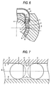
- the retaining piece 1 is received in the endless circulating path 3 of a ball screw as shown in Fig. 6 while being carried by the ball 2 at both sides thereof in such an arrangement that it can flexibly follow the angular change of the circulating path 3.
- the reference numeral 4 indicates the screw shaft of a ball screw on the periphery of which a nut 5 is fitted.
- the outer periphery of the screw shaft 4 and the inner periphery of the nut 5 have helical ball rolling paths 7, 8 formed opposed to each other, respectively.
- the ball rolling groove 8 on the nut 5 and the ball rolling groove 7 on the screw shaft 4 form a ball rolling path 9.
- the nut 5 includes a tube 10 provided therein to form a return path connecting one end of the ball rolling path 9 to the other.
- the tube 10 and the ball rolling path 9 form an endless circulating path 3 in which a number of balls 3 and retaining pieces 1 each interposed therebetween are received.
- the balls 2 are endlessly circulated in the endless circulating path 3.
- the retaining piece 1 makes sliding movement with the balls 2.
- the frictional force developed by this sliding movement doesn't prevent the rolling movement of the balls 2 on the rolling grooves 7, 8, it results in no deterioration of the operating characteristics or the life of the balls 2 and the rolling grooves 7, 8.
- an elastomer having elastic property may be used.
- a material having elasticity essentially has swell characteristics and thus tends to absorb an oil or water to swell.
- the retaining piece 1 has a groove-like notch 11 formed on the periphery thereof to become an elastic structure itself as shown in Fig. 7.
- the mold die for forming the retaining piece 1 is complicated or the retaining piece 1 has a complicated configuration in the outer periphery thereof, making it more likely that the retaining piece 1 can be caught by the inner wall of the circulating path 3.
- the retaining piece 1 is adjusted to have a slight clearance from the inner wall of the circulating path 3 and is incorporated in the circulating path 3.
- the filling clearance of the retaining piece 1 is too small or the retaining pieces 1 are filled in the circulating path 3 too much, the rolling movement of the balls 2 is prevented, adversely affecting the operating characteristics or the life of the linear motion device.
- the filling clearance of the retaining piece 1 is too great, it causes the retaining piece 1 to fall down or be caught by the inner wall of the circulating path 3.
- the filling clearance of the retaining piece 1 must be severely controlled. Accordingly, it takes much time and labor to adjust the filling clearance of the retaining piece 1.
- An aim of the invention is to provide a linear motion device which includes a retaining piece having a rigidity reduced by a simple means to exhibit good operating characteristics and durability even when it is particularly under a low preload load.
- a linear motion device including an inner member and an outer member, cooperatively forming a ball circulating path therebetween;
- the adjustment of the rigidity of the retaining piece is accomplished by predetermining the bore diameter of a through-hole formed at the central portion to a range of from 35% to 65% of the ball.
- FIG. 1A and 1B illustrate a related art retaining piece 1 for comparison and a retaining piece la according to the invention, respectively.
- Each of these retaining pieces 1, la is in the form of disc having a smaller outer diameter than the diameter of a ball 2 and has a circular concave portion 12 at the both axial ends thereof in which the ball 2 is slidably fitted.
- Each of the retaining pieces 1, 1a also has a circular through-hole 13 formed at the central portion of the concave portion 12 extending from one of the concave portions 12 to the other.
- the concave portion 12 has a gothic or conical section in which a part of the surface of the ball 12 is fitted.
- the chain line P shown in Figs. 1A and 1B indicates the position at which the ball 12 comes in contact with the concave portion 12.
- the related art retaining piece 1 and the retaining piece la of the invention are made of the same synthetic resin, e.g., nylon.
- the bore diameter D 1 of the through-hole 13 is about 30% of the diameter of the ball 2. This size causes no problems in ordinary use. However, as previously mentioned, this retaining piece 1 cannot exhibit predetermined operating characteristics in a ball screw which operates under a low preload load and thus is subject to slippage of ball 2 on the rolling grooves 7, 8 with ease.
- the bore diameter D 2 of the through-hole 13 is greater than that of the related art retaining piece and from about 35% to 65% of the diameter of the ball 2.
- the retaining piece la provided with a through-hole 13 having an increased bore diameter exhibits a reduced rigidity and thus undergoes flexible deformation by a force in an axial direction, that is, a force in a direction connecting between the centers of balls (a ball-to-ball direction force) applied to the retaining piece by the balls 2 disposed at both sides thereof.
- Fig. 2 illustrates the comparison in rigidity of the retaining piece la of the invention with the related art retaining piece 1, i.e., a relationship of the ball-to-ball direction force and the displacement of the retaining pieces 1, 1a by elastic deformation.
- the retaining piece la of the invention exhibits a greater displacement by elastic deformation (compression) with respect to the ball-to-ball direction force and a smaller rigidity than the related art retaining piece 1.
- the rigidity of the retaining piece 1a can be arbitrarily adjusted by changing the bore diameter of the through-hole 13.
- the bore diameter of the through-hole 13 is predetermined to a range of from about 35% to 65% of the diameter of the ball 2 so that the ratio of the ball-to-ball direction force applied to the retaining piece la by the balls disposed at the both sides thereof to the elastic displacement of the retaining piece by this force is from 0.1 to 10 [N/ ⁇ m].
- the bore diameter of the through-hole 13 is predetermined to 50% of the diameter of the ball 2 so that the ratio of the ball-to-ball direction force applied to the retaining piece la by the balls disposed at the both sides thereof to the elastic displacement of the retaining piece by this force is set to be 2 [N/ ⁇ m].
- a ball screw including a steel ball having a diameter of 3.175 mm as a ball and a shaft having a diameter of 32 mm which operates at a lead of 5 mm and a preload of 1,200 N.
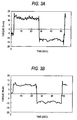
- Fig. 3A illustrates the dynamic torque characteristics of a ball screw having the related art retaining piece 1 incorporated in the circulating path 3.
- Fig. 3B illustrates the dynamic torque characteristics of a ball screw having the retaining piece 1a of the invention incorporated in the circulating path 3.
- the operating characteristics of ball screws which are subject to slippage of balls 2 with the rolling grooves 7, 8, particularly, under low preload can be improved by adjusting the rigidity of the retaining piece la such that the ratio of the ball-to-ball direction force applied to the retaining piece la by the ball disposed at the both sides thereof to the elastic displacement of the retaining piece by this force is from 0.1 to 10 [N/ ⁇ m].
- the retaining piece la since the retaining piece la has a proper elasticity, excessive force cannot be applied to the surface of the concave portion 12 in which the ball 2 fits, making it possible to inhibit the abrasion on the surface of the concave portion 12 and hence obtain a good stability over an extended period of time.
- the rigidity of the retaining piece la is adjusted by changing the size of the through-hole 13 of the retaining piece 1a.
- the periphery of the retaining piece la can be kept smooth, making it possible toprevent catching in the circulating path 3.
- the mold for forming the retaining piece la doesn't need to be complicated, making it possible to prepare the retaining piece easily at a reduced cost.
- a retaining piece having a rigidity as high as greater than the range of from 0.1 to 10 N/ ⁇ m as calculated in terms of ratio of the ball-to-ball direction force to displacement is used.
- Fig. 4 illustrates a retaining piece 1b according to a second embodiment of the invention.
- the retaining piece 1b has a slit 20 formed to extend from the outer periphery thereof to the peripheral edge of the through-hole 13. With the slit 20, the retaining piece 1b is in the form of substantially "C" as viewed in the axial direction.
- the rigidity of the retaining piece 1b can be adjusted to a predetermined value, making it possible to improve the operating characteristics of the ball screw.
- the invention can be combined with a material having an elastic force such as elastomeric material.
- the bore diameter of the through-hole of the retaining piece is adjusted to reduce the rigidity of the retaining piece and hence the frictional force of the balls with the retaining piece, making it possible to inhibit slippage of the balls with the ball rolling groove.
- a linear motion device which operates under a preload load can be provided with enhanced operating characteristics and durability.
Landscapes
- Engineering & Computer Science (AREA)
- General Engineering & Computer Science (AREA)
- Mechanical Engineering (AREA)
- Transmission Devices (AREA)
- Bearings For Parts Moving Linearly (AREA)
- Rolling Contact Bearings (AREA)
Applications Claiming Priority (2)
| Application Number | Priority Date | Filing Date | Title |
|---|---|---|---|
| JP2002075059 | 2002-03-18 | ||
| JP2002075059A JP2003269464A (ja) | 2002-03-18 | 2002-03-18 | 直動装置 |
Publications (3)
| Publication Number | Publication Date |
|---|---|
| EP1347187A2 true EP1347187A2 (fr) | 2003-09-24 |
| EP1347187A3 EP1347187A3 (fr) | 2004-11-03 |
| EP1347187B1 EP1347187B1 (fr) | 2006-01-18 |
Family
ID=27785167
Family Applications (1)
| Application Number | Title | Priority Date | Filing Date |
|---|---|---|---|
| EP03006142A Expired - Lifetime EP1347187B1 (fr) | 2002-03-18 | 2003-03-18 | Palier linéaire |
Country Status (4)
| Country | Link |
|---|---|
| US (1) | US7159484B2 (fr) |
| EP (1) | EP1347187B1 (fr) |
| JP (1) | JP2003269464A (fr) |
| DE (1) | DE60303231T2 (fr) |
Cited By (1)
| Publication number | Priority date | Publication date | Assignee | Title |
|---|---|---|---|---|
| CN100378354C (zh) * | 2002-08-09 | 2008-04-02 | 日本精工株式会社 | 线性移动装置 |
Families Citing this family (8)
| Publication number | Priority date | Publication date | Assignee | Title |
|---|---|---|---|---|
| JP4773789B2 (ja) * | 2005-05-26 | 2011-09-14 | 富士フイルム株式会社 | 成形用金型及びその製造方法 |
| US20130199314A1 (en) * | 2012-01-26 | 2013-08-08 | Roller Bearing Company Of America, Inc. | Flywheel assembly for gyroscopic applications having ball bearing slug separators |
| US9447820B2 (en) * | 2014-04-23 | 2016-09-20 | General Electric Company | Spacer assembly for a bearing |
| US9303689B2 (en) | 2014-04-29 | 2016-04-05 | Roller Bearing Company Of America, Inc. | Non-rhythmically spaced rolling elements for reduction in bearing non-repeatable run-out |
| JP6385006B2 (ja) * | 2015-01-23 | 2018-09-05 | 三菱重工コンプレッサ株式会社 | 直動機構、弁装置、及び蒸気タービン |
| KR101934974B1 (ko) | 2018-06-12 | 2019-01-03 | 채수홍 | 초경 절삭팁 성형 장치 및 방법 |
| CN109296639B (zh) * | 2018-12-06 | 2023-03-31 | 株洲易力达机电有限公司 | 新型滑动副总成 |
| CN112648286A (zh) * | 2019-10-10 | 2021-04-13 | 南京荧河谷科技有限公司 | 一种挤油式自润滑的推力轴承的使用方法 |
Family Cites Families (8)
| Publication number | Priority date | Publication date | Assignee | Title |
|---|---|---|---|---|
| NL105086C (fr) | 1958-02-13 | |||
| FR1332286A (fr) * | 1961-07-28 | 1963-07-12 | Rothe Erde Eisenwerk | Cages pour grandes couronnes de roulements |
| JP3695195B2 (ja) * | 1998-06-02 | 2005-09-14 | 日本精工株式会社 | ボールねじ機構、および直動装置 |
| US6415676B1 (en) * | 1999-10-26 | 2002-07-09 | Tsubaki Nakashima Co., Ltd. | Ball screw device having spacers |
| US6565947B2 (en) * | 2000-01-11 | 2003-05-20 | Nsk Ltd. | Retaining piece structure |
| TW412620B (en) | 2000-03-03 | 2000-11-21 | Hiwin Tech Corp | Linear slide rail with spacer |
| DE10132431A1 (de) * | 2000-07-05 | 2002-04-04 | Nsk Ltd | Lineare Führungsvorrichtung |
| JP2002089651A (ja) * | 2000-09-12 | 2002-03-27 | Thk Co Ltd | 転がり案内装置の転動体スペーサ |
-
2002
- 2002-03-18 JP JP2002075059A patent/JP2003269464A/ja active Pending
-
2003
- 2003-03-17 US US10/388,482 patent/US7159484B2/en not_active Expired - Fee Related
- 2003-03-18 DE DE60303231T patent/DE60303231T2/de not_active Expired - Fee Related
- 2003-03-18 EP EP03006142A patent/EP1347187B1/fr not_active Expired - Lifetime
Non-Patent Citations (1)
| Title |
|---|
| None |
Cited By (1)
| Publication number | Priority date | Publication date | Assignee | Title |
|---|---|---|---|---|
| CN100378354C (zh) * | 2002-08-09 | 2008-04-02 | 日本精工株式会社 | 线性移动装置 |
Also Published As
| Publication number | Publication date |
|---|---|
| US7159484B2 (en) | 2007-01-09 |
| DE60303231T2 (de) | 2006-07-20 |
| EP1347187B1 (fr) | 2006-01-18 |
| JP2003269464A (ja) | 2003-09-25 |
| EP1347187A3 (fr) | 2004-11-03 |
| DE60303231D1 (de) | 2006-04-06 |
| US20030172760A1 (en) | 2003-09-18 |
Similar Documents
| Publication | Publication Date | Title |
|---|---|---|
| US7146869B2 (en) | Ball screw device and linear motion device | |
| US6095009A (en) | Ball screw having spacers | |
| US6513978B2 (en) | Rolling element spacers for rolling guide units | |
| EP1347187B1 (fr) | Palier linéaire | |
| US6616335B2 (en) | Rolling element spacer in rolling guide device | |
| US6722223B2 (en) | Ball screw | |
| JP2001021018A (ja) | ボールねじ | |
| JP2022157860A (ja) | 転がり案内装置 | |
| JP4280376B2 (ja) | 直動転がり案内ユニット | |
| EP1318330B1 (fr) | Appareil avec vis à billes | |
| EP1318331B1 (fr) | Appareil avec vis a billes | |
| EP1138965A1 (fr) | Séparateur de billes pour un dispositif de guidage à roulement et apparail de guidage à roulement incorpérant des séparateurs de billes | |
| JP2000213538A (ja) | 直動案内軸受装置 | |
| JP4244557B2 (ja) | 循環方式のボールねじ | |
| JP2024123987A (ja) | ボールねじ | |
| EP1528273A1 (fr) | Unite d'entrainement direct | |
| JP2024159064A (ja) | 直動装置 | |
| US20040151406A1 (en) | Direct drive unit | |
| JP2004150587A (ja) | 直動装置用スペーサ及び直動装置 | |
| JP2004028221A (ja) | 保持ピース入り直動装置 | |
| JP2017125521A (ja) | 転がり装置 | |
| KR20020089774A (ko) | 구름 안내 장치의 전동체 스페이서 |
Legal Events
| Date | Code | Title | Description |
|---|---|---|---|
| PUAI | Public reference made under article 153(3) epc to a published international application that has entered the european phase |
Free format text: ORIGINAL CODE: 0009012 |
|
| AK | Designated contracting states |
Kind code of ref document: A2 Designated state(s): AT BE BG CH CY CZ DE DK EE ES FI FR GB GR HU IE IT LI LU MC NL PT RO SE SI SK TR |
|
| AX | Request for extension of the european patent |
Extension state: AL LT LV MK |
|
| PUAL | Search report despatched |
Free format text: ORIGINAL CODE: 0009013 |
|
| AK | Designated contracting states |
Kind code of ref document: A3 Designated state(s): AT BE BG CH CY CZ DE DK EE ES FI FR GB GR HU IE IT LI LU MC NL PT RO SE SI SK TR |
|
| AX | Request for extension of the european patent |
Extension state: AL LT LV MK |
|
| RIC1 | Information provided on ipc code assigned before grant |
Ipc: 7F 16C 29/06 A Ipc: 7F 16C 19/20 B Ipc: 7F 16H 25/22 B |
|
| 17P | Request for examination filed |
Effective date: 20041210 |
|
| GRAP | Despatch of communication of intention to grant a patent |
Free format text: ORIGINAL CODE: EPIDOSNIGR1 |
|
| AKX | Designation fees paid |
Designated state(s): DE |
|
| GRAS | Grant fee paid |
Free format text: ORIGINAL CODE: EPIDOSNIGR3 |
|
| GRAA | (expected) grant |
Free format text: ORIGINAL CODE: 0009210 |
|
| AK | Designated contracting states |
Kind code of ref document: B1 Designated state(s): DE |
|
| REF | Corresponds to: |
Ref document number: 60303231 Country of ref document: DE Date of ref document: 20060406 Kind code of ref document: P |
|
| PLBE | No opposition filed within time limit |
Free format text: ORIGINAL CODE: 0009261 |
|
| STAA | Information on the status of an ep patent application or granted ep patent |
Free format text: STATUS: NO OPPOSITION FILED WITHIN TIME LIMIT |
|
| 26N | No opposition filed |
Effective date: 20061019 |
|
| PGFP | Annual fee paid to national office [announced via postgrant information from national office to epo] |
Ref country code: DE Payment date: 20080313 Year of fee payment: 6 |
|
| PG25 | Lapsed in a contracting state [announced via postgrant information from national office to epo] |
Ref country code: DE Free format text: LAPSE BECAUSE OF NON-PAYMENT OF DUE FEES Effective date: 20091001 |