EP1347207A1 - Dispositif d'actionnement de vis à rouleaux satellites - Google Patents
Dispositif d'actionnement de vis à rouleaux satellites Download PDFInfo
- Publication number
- EP1347207A1 EP1347207A1 EP03290684A EP03290684A EP1347207A1 EP 1347207 A1 EP1347207 A1 EP 1347207A1 EP 03290684 A EP03290684 A EP 03290684A EP 03290684 A EP03290684 A EP 03290684A EP 1347207 A1 EP1347207 A1 EP 1347207A1
- Authority
- EP
- European Patent Office
- Prior art keywords
- rod
- drive
- drive rod
- longitudinal
- support
- Prior art date
- Legal status (The legal status is an assumption and is not a legal conclusion. Google has not performed a legal analysis and makes no representation as to the accuracy of the status listed.)
- Granted
Links
- 238000005096 rolling process Methods 0.000 claims description 12
- 230000008878 coupling Effects 0.000 claims description 2
- 238000010168 coupling process Methods 0.000 claims description 2
- 238000005859 coupling reaction Methods 0.000 claims description 2
- 230000033001 locomotion Effects 0.000 description 3
- 210000000056 organ Anatomy 0.000 description 3
- 238000012550 audit Methods 0.000 description 1
- 230000005540 biological transmission Effects 0.000 description 1
- 210000005069 ears Anatomy 0.000 description 1
- 238000004804 winding Methods 0.000 description 1
Images


Classifications
-
- F—MECHANICAL ENGINEERING; LIGHTING; HEATING; WEAPONS; BLASTING
- F16—ENGINEERING ELEMENTS AND UNITS; GENERAL MEASURES FOR PRODUCING AND MAINTAINING EFFECTIVE FUNCTIONING OF MACHINES OR INSTALLATIONS; THERMAL INSULATION IN GENERAL
- F16H—GEARING
- F16H25/00—Gearings comprising primarily only cams, cam-followers and screw-and-nut mechanisms
- F16H25/18—Gearings comprising primarily only cams, cam-followers and screw-and-nut mechanisms for conveying or interconverting oscillating or reciprocating motions
- F16H25/20—Screw mechanisms
- F16H25/22—Screw mechanisms with balls, rollers, or similar members between the co-operating parts; Elements essential to the use of such members
- F16H25/2247—Screw mechanisms with balls, rollers, or similar members between the co-operating parts; Elements essential to the use of such members with rollers
- F16H25/2252—Planetary rollers between nut and screw
-
- F—MECHANICAL ENGINEERING; LIGHTING; HEATING; WEAPONS; BLASTING
- F16—ENGINEERING ELEMENTS AND UNITS; GENERAL MEASURES FOR PRODUCING AND MAINTAINING EFFECTIVE FUNCTIONING OF MACHINES OR INSTALLATIONS; THERMAL INSULATION IN GENERAL
- F16H—GEARING
- F16H25/00—Gearings comprising primarily only cams, cam-followers and screw-and-nut mechanisms
- F16H25/18—Gearings comprising primarily only cams, cam-followers and screw-and-nut mechanisms for conveying or interconverting oscillating or reciprocating motions
- F16H25/20—Screw mechanisms
- F16H2025/2062—Arrangements for driving the actuator
- F16H2025/2075—Coaxial drive motors
-
- Y—GENERAL TAGGING OF NEW TECHNOLOGICAL DEVELOPMENTS; GENERAL TAGGING OF CROSS-SECTIONAL TECHNOLOGIES SPANNING OVER SEVERAL SECTIONS OF THE IPC; TECHNICAL SUBJECTS COVERED BY FORMER USPC CROSS-REFERENCE ART COLLECTIONS [XRACs] AND DIGESTS
- Y10—TECHNICAL SUBJECTS COVERED BY FORMER USPC
- Y10T—TECHNICAL SUBJECTS COVERED BY FORMER US CLASSIFICATION
- Y10T74/00—Machine element or mechanism
- Y10T74/18—Mechanical movements
- Y10T74/18568—Reciprocating or oscillating to or from alternating rotary
- Y10T74/18576—Reciprocating or oscillating to or from alternating rotary including screw and nut
- Y10T74/18664—Shaft moves through rotary drive means
-
- Y—GENERAL TAGGING OF NEW TECHNOLOGICAL DEVELOPMENTS; GENERAL TAGGING OF CROSS-SECTIONAL TECHNOLOGIES SPANNING OVER SEVERAL SECTIONS OF THE IPC; TECHNICAL SUBJECTS COVERED BY FORMER USPC CROSS-REFERENCE ART COLLECTIONS [XRACs] AND DIGESTS
- Y10—TECHNICAL SUBJECTS COVERED BY FORMER USPC
- Y10T—TECHNICAL SUBJECTS COVERED BY FORMER US CLASSIFICATION
- Y10T74/00—Machine element or mechanism
- Y10T74/19—Gearing
- Y10T74/19642—Directly cooperating gears
- Y10T74/19698—Spiral
- Y10T74/19702—Screw and nut
- Y10T74/19744—Rolling element engaging thread
- Y10T74/19781—Non-recirculating rolling elements
- Y10T74/19791—Cylindrical or quasi-cylindrical roller element [e.g., inclined roller, etc.]
- Y10T74/19795—Parallel to shaft
Definitions
- the present invention relates to the field of devices actuators in which the motion transmission between two concentric longitudinal parts, rotating relative to one another, is obtained by means of longitudinal rollers and proposes improvements to such devices.
- the actuating device comprises a support; a longitudinal drive shaft including an end portion back is rotatably mounted in said support and a portion of which front end has an external thread and on at least a part of annular, gear teeth; a longitudinal sheath placed around and coaxially with said drive rod and having a thread inside; a series of rollers placed longitudinally between said rod of training and said sheath and having an external thread in taken with on the one hand the threading of said drive shaft and other the thread of said sheath and gear teeth engaged with the gear teeth of said drive shaft, the helix angle of the aforementioned thread of said rollers being equal to the helix angle of the thread of said drive rod and being different from the helix angle of the thread said sheath; and means for rotating said rod, carried by said support and whose driving shaft is coupled to the rear end of this rod drive.
- the device can advantageously include longitudinal guiding means connecting said support and said sheath.
- the device preferably comprises end rings placed on either side of said rollers and having longitudinal holes in which are respectively engaged ends of these rollers.
- said drive rod comprises preferably two annular gear teeth parts between which extends, at least in part, its aforementioned thread.
- the device can advantageously comprising a sliding ring carried by said sheath and placed around the portion of said drive shaft located between its portion before and its rear part mentioned above.
- said sheath preferably comprises a longitudinal guide rod engaged in a guide bore of said drive rod.
- said driving rod is preferably mounted in said support by means of a rolling bearing forming axial stop.
- said training means comprises of preferably a motor whose housing carries said motor shaft and is fixed audit support.
- the driving shaft of said means of training and said drive rod are aligned and present between them means of coupling in rotation.
- the driving shaft of said means of training and said drive rod are aligned and are formed of a piece to form a drive shaft.
- said drive shaft is preferably rotatably mounted in said support via a bearing bearing forming an axial stop and, opposite to its aforementioned threaded portion, in a casing of the drive means fixed to said support by through a rolling bearing.
- said rod training is monobloc.
- said drive rod includes a main longitudinal part on which are reported a sleeve having its aforementioned thread and / or at least one ring having said annular gear teeth portion.
- the aforementioned thread and the gear teeth mentioned above of said driving rod preferably have the same outside diameter.
- said driving rod may have a groove formed between its aforementioned thread and its annular toothed portion gear.
- the gear teeth of said rollers can be performed in their aforementioned threaded portion.
- the device preferably comprises means forming abutments cooperating with said end rings and placed on either side of the longitudinal stack constituted by these end rings and rollers.
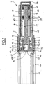
- an actuator 1 which comprises a tubular support 2 which comprises a longitudinal body 3 whose envelope 4 is substantially of square section and a longitudinal cylindrical portion 5 which extends forward body 3.
- the body 3 has a longitudinal bore 6 which ends side of the cylindrical portion 5 by an annular shoulder 7.
- the actuator 1 comprises a longitudinal training rod 8 which extends axially in the support 2 and whose end portion rear 9 is carried by the body 3 of the support 2 via a rolling bearing 10 forming axial stops in both directions.
- this rolling bearing 10 comprises two contiguous ball bearings 11 and 12 whose outer rings are taken between on the one hand the shoulder 7 of the body 3 by through a ring 13 and secondly by a screwed ring 14 in a rear thread of the bore 6 and whose inner rings are taken between on the one hand a shoulder before 15 of the part rear end 9 of the rod 8 and secondly a ring 16 screwed on a threaded rear portion of the rear end portion 9 of the rod 8.
- the front end portion 17, located at a distance from its portion 9, has an outer threaded portion 18 and, on either side of this thread 18, parts with straight gear teeth 19 and 20 separated from the thread 18 by annular grooves 21 and 22, the 18 and the toothed portions 19 and 20 having in the example the same outside diameter.
- the front end portion 17 further has, in front of its toothed portion 20, a cylindrical end portion 23 in which is formed an annular groove 23 and, behind the toothed portion 19, a cylindrical portion 25 in which is formed a ring groove 26.
- the longitudinal rod 8 has a cylindrical portion intermediate 27 of reduced diameter relative to the outer diameter of its front end portion 17.
- the actuator 1 further has a series of longitudinal rollers 28 which are distributed around the front end portion 17 of the shank 8 and which have a thread on their length. threads of the rollers 28 are engaged with the threading 18 of the rod 8.
- the rollers have, in their end portions, on the one hand a part with straight gear teeth 29 engaged with the gear teeth 20 and secondly a toothed gear portion straight 30 engaged with the gear teeth 19.
- the longitudinal rollers 19 have end portions before 31 cylinders, of deduced diameters, which are engaged respectively in holes 32 formed in a front ring 33 mounted around the cylindrical end portion 23 of the rod 8, this ring being held by an annular ring 34 installed in the throat 24 of this end part 23.
- the longitudinal rollers 28 also have portions cylindrical rear terminals 35, of reduced diameter, which are engaged in holes 36 formed in a rear ring 27 mounted around the cylindrical part 25, this ring 37 being maintained by an annular ring 38 installed in the groove 26 of this part cylindrical 25.
- the threading 18 of the front end portion 17 of the rod longitudinal 8 and the threads of the rollers 28 have angles identical helix so that when the assembly constituted by the longitudinal rollers 28 and the retaining rings 33 and 37 turn around the rod 9, the rollers turn relative to the rod 8 without moving longitudinally.
- the actuator 1 further comprises a longitudinal sleeve cylindrical 39 which is installed around and away from the part front end 17 of the longitudinal rod 8 and the part intermediate 27 and engaged within the cylindrical portion 5 of the support 2.
- the longitudinal sheath 39 has an internal thread 40 which is engaged with the threads 29 of the longitudinal rollers 28 and whose helix angle is different from the helix angle of these threads 29.
- the cylindrical portion 5 of the support 2 has a longitudinal lower guide groove 41 and the sheath 39 carries externally a key 42 engaged in this groove 41.
- the actuator 1 comprises in in addition to a rear electric motor 44 which has a longitudinal housing 45 which has a front face 46 coupled to a rear face 47 of the body 3 of the support 2.
- the housing 45 has four ears before 48 traversed by longitudinal fastening screws screwed into the corners of the body 3 of the support 2.
- the electric motor 44 has a motor shaft 50 whose front end portion 51 is engaged in a longitudinal bore 52 formed by the rear in the rear end portion 9 of the rod longitudinal 8, a key 53 rotatingly connecting the drive shaft 50 and the longitudinal rod 8.
- the actuator 1 which has just been described can be installed between two unrepresented bodies, to move longitudinally relative to each other, the body 3 of the support 2 being attached to one of the organs, for example through the intermediary of two opposed pivots 3a and 3b and the front end of the sleeve 39 being connected to the other, the sheath 39 having for this purpose a threaded portion 54 of increased diameter in the front inner part
- Its support 56 only has a corresponding body 57 to the body 3 of the support 2, the cylindrical part before 5 of the latter being deleted.
- Its longitudinal drive rod 58 has a part cylindrical intermediate 59 whose diameter is larger than the outer diameter of its front end portion 60.
- Its longitudinal sleeve 61 is cylindrical and carries in a non-threaded rear bore an intermediate slip ring 62 which surrounds and bears on the cylindrical intermediate portion 59.
- the sleeve 61 is not immobilized in rotation relative to the support 56, this immobilization being able to be provided by the organs to be moved to which they are connected as we have mentioned above.
- Its longitudinal drive rod 64 has a bore cylindrical 65 in which is engaged by the front a rod longitudinal guide 67 which has on its rear part projecting annular portions 68 and 69 in contact with the bore 65.
- guide rod 67 has a front portion 70 of increased diameter which is disposed forward of the front end of the drive rod 64 and which for example is screwed into a threaded front bore 71 of the longitudinal sleeve 66, this thread having an increased diameter more large than the internal thread 72 of this sheath corresponding to the thread 40.
- the guide rod 67 contributes to the longitudinal guidance of the sheath 66 when the latter moves away from the body 73 of its support 74.
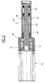
- a actuator 75 which differs from the actuator 1 described with reference in Figures 1 to 4 essentially by the fact that its drive rod 76 and the motor shaft 77 of its electric motor 78 are of a single piece which constitutes a drive shaft 79.
- This drive shaft 79 comprises a median portion 80 which is carried by the body 81 of its support 82 via a rolling bearing 83 which corresponds to the rolling bearing 10.
- the drive shaft 79 has a longitudinal rod cylindrical rear 84 which is of reduced diameter compared to that of its middle part 80 and which carries the winding of the rotor 85 of the motor 78, a rolling bearing 86 being interposed between the end portion rear of the cylindrical rod 84 and the rear portion of the housing 87 of the motor 78.
- FIG. 8 it can be seen that there has been shown a actuator 87 which differs from that shown in Figure 7 and described above essentially by the fact that the end portion before 88 of its front drive shaft 89 of its drive shaft 90 has a cylindrical sleeve 91 reported to the periphery of which are provided the thread 18, the gear teeth 19 and 20, the grooves 21 and 22, the cylindrical parts 23 and 25 and the grooves 24 and 25 of the front end portion 17 of the driving rod 8 of the example described with reference to Figures 1 to 3, this sleeve reported 91 being for example mounted around a portion 89a of reduced diameter of the end portion of the rod 89 and fixed longitudinally between a shoulder 89b of this rod 89 and a front washer 91 maintained by a screw 92 screwed axially into the end of the rod 89. reported sleeve 91 could be sintered or welded on the rod 89.
Landscapes
- Engineering & Computer Science (AREA)
- General Engineering & Computer Science (AREA)
- Mechanical Engineering (AREA)
- Transmission Devices (AREA)
- Yarns And Mechanical Finishing Of Yarns Or Ropes (AREA)
- Vehicle Body Suspensions (AREA)
- Rollers For Roller Conveyors For Transfer (AREA)
- Connection Of Motors, Electrical Generators, Mechanical Devices, And The Like (AREA)
Abstract
Description
- la figure 1 représente une coupe longitudinale d'un premier actionneur selon l'invention ;
- la figure 2 représente une coupe longitudinale d'une partie agrandie de l'actionneur de la figure 1 ;
- la figure 3 représente une coupe transversale de l'actionneur de la figure 1 ;
- la figure 4 représente une vue en bout, par l'arrière, de l'actionneur de la figure 1 ;
- la figure 5 représente une coupe longitudinale d'un second actionneur selon l'invention ;
- la figure 6 représente une coupe longitudinale d'un troisième actionneur selon l'invention ;
- la figure 7 représente une coupe longitudinale d'un quatrième actionneur selon l'invention ;
- la figure 8 représente une coupe longitudinale d'un cinquième actionneur selon l'invention.
Claims (17)
- Dispositif d'actionnement comprenant :un support (2) ;une tige d'entraínement longitudinale (8) dont une partie d'extrémité arrière (9) est montée tournante dans ledit support et dont une partie d'extrémité avant (17) présente un filetage extérieur (18) et, sur au moins une partie annulaire, des dents d'engrenage (19) ;un fourreau longitudinal (39) placé autour et coaxialement à ladite tige d'entraínement et présentant un filetage intérieur ;une série de rouleaux (28) placés longitudinalement entre ladite tige d'entraínement et ledit fourreau et présentant un filetage extérieur en prise avec d'une part le filetage de ladite tige d'entraínement et d'autre part le filetage dudit fourreau et des dents d'engrenage (30) en prise avec les dents d'engrenage de ladite tige d'entraínement, l'angle d'hélice du filetage précité desdits rouleaux étant égal à l'angle d'hélice du filetage de ladite tige d'entraínement et étant différent de l'angle d'hélice du filetage précité dudit fourreau ;et un moyen d'entraínement en rotation (44) de ladite tige d'entraínement (8), porté par ledit support (2) et dont l'arbre moteur (50) est couplé à l'extrémité arrière de cette tige d'entraínement (8).
- Dispositif selon la revendication 1, caractérisé par le fait qu'il comprend des moyens de guidage longitudinal (41, 42) reliant ledit support (3) et ledit fourreau (39).
- Dispositif selon l'une des revendications 1 et 2, caractérisé par le fait qu'il comprend des bagues d'extrémité (33, 37) placées de part et d'autre desdits rouleaux et présentant des trous longitudinaux dans lesquels sont respectivement engagées des extrémités de ces rouleaux.
- Dispositif selon l'une quelconque des revendications précédentes, caractérisé par le fait que ladite tige d'entraínement (8) comprend deux parties annulaires à dents d'engrenage (19, 20) entre lesquelles s'étend, au moins en partie, son filetage précité.
- Dispositif selon l'une quelconque des revendications précédentes, caractérisé par le fait qu'il comprend une bague de glissement (62) portée par ledit fourreau et placée autour de la partie de ladite tige d'entraínement située entre sa partie avant et sa partie arrière précitées.
- Dispositif selon l'une quelconque des revendications précédentes, caractérisé par le fait que ledit fourreau comprend une tige longitudinale de guidage (67) engagée dans un alésage de guidage (65) de ladite tige d'entraínement (64).
- Dispositif selon l'une quelconque des revendications précédentes, caractérisé par le fait que ladite tige d'entraínement (8) est montée dans ledit support par l'intermédiaire d'un palier à roulement (10) formant butée axiale.
- Dispositif selon l'une quelconque des revendications précédentes, caractérisé par le fait que ledit moyen d'entraínement comprend un moteur (44) dont le carter (45) porte ledit arbre moteur (51) et est fixé audit support (2).
- Dispositif selon l'une quelconque des revendications précédentes, caractérisé par le fait que l'arbre moteur (50) dudit moyen d'entraínement et ladite tige d'entraínement (8) sont alignés et présentent entre eux des moyens d'accouplement en rotation (53).
- Dispositif selon l'une quelconque des revendications 1 à 8, caractérisé par le fait que l'arbre moteur (77) dudit moyen d'entraínement et ladite tige d'entraínement (76) sont alignés et sont formés d'une pièce pour constituer un arbre d'entraínement (79).
- Dispositif selon la revendication 10, caractérisé par le fait que ledit arbre d'entraínement (79) est monté tournant dans ledit support 82) par l'intermédiaire d'un palier à roulement (83) formant butée axiale et, à l'opposé de sa partie filetée précitée, dans un carter (87) du moyen d'entraínement fixé audit support , par l'intermédiaire d'un palier à roulement (86).
- Dispositif selon l'une quelconque des revendications précédentes, caractérisé par le fait que ladite tige d'entraínement (8) est monobloc.
- Dispositif selon l'une quelconque des revendications 1 à 11, caractérisé par le fait que ladite tige d'entraínement (89) comprend une partie principale longitudinale sur laquelle sont rapportés un manchon (91) présentant son filetage précité et/ou au moins une bague présentant sa partie annulaire précitée à dents d'engrenage.
- Dispositif selon l'une quelconque des revendications précédentes, caractérisé par le fait que le filetage précité et les dents d'engrenage précitées de ladite tige d'entraínement (8) présentent le même diamètre extérieur.
- Dispositif selon l'une quelconque des revendications précédentes, caractérisé par le fait que ladite tige d'entraínement (8) présente au moins une gorge (21) ménagée entre son filetage précité et sa partie annulaire à dents d'engrenage.
- Dispositif selon l'une quelconque des revendications précédentes, caractérisé par le fait que les dents d'engrenage desdits rouleaux sont réalisées dans leur partie filetée précitée.
- Dispositif selon l'une quelconque des revendications précédentes, caractérisé par le fait qu'il comprend des moyens (38) formant butées coopérant avec lesdites bagues d'extrémité et placées de part et d'autre de l'empilage longitudinal constitué par ces bagues d'extrémité et les rouleaux.
Applications Claiming Priority (2)
| Application Number | Priority Date | Filing Date | Title |
|---|---|---|---|
| FR0203489 | 2002-03-20 | ||
| FR0203489A FR2837550B1 (fr) | 2002-03-20 | 2002-03-20 | Dispositif d'actionnement a rouleaux intermediaires |
Publications (2)
| Publication Number | Publication Date |
|---|---|
| EP1347207A1 true EP1347207A1 (fr) | 2003-09-24 |
| EP1347207B1 EP1347207B1 (fr) | 2005-06-15 |
Family
ID=27772250
Family Applications (1)
| Application Number | Title | Priority Date | Filing Date |
|---|---|---|---|
| EP03290684A Expired - Lifetime EP1347207B1 (fr) | 2002-03-20 | 2003-03-18 | Dispositif d'actionnement de vis à rouleaux satellites |
Country Status (5)
| Country | Link |
|---|---|
| US (1) | US7000495B2 (fr) |
| EP (1) | EP1347207B1 (fr) |
| AT (1) | ATE298053T1 (fr) |
| DE (1) | DE60300831T2 (fr) |
| FR (1) | FR2837550B1 (fr) |
Cited By (5)
| Publication number | Priority date | Publication date | Assignee | Title |
|---|---|---|---|---|
| WO2012072389A1 (fr) * | 2010-11-30 | 2012-06-07 | Schaeffler Technologies AG & Co. KG | Cric |
| FR2984443A1 (fr) * | 2011-12-16 | 2013-06-21 | Skf Ab | Vis a rouleaux. |
| CN105972176A (zh) * | 2015-03-13 | 2016-09-28 | 舍弗勒技术股份两合公司 | 行星滚柱丝杠(pwg) |
| FR3098268A1 (fr) * | 2019-07-05 | 2021-01-08 | Maateecs Consulting | Vis à rouleaux satellites a dentures asymétriques |
| EP4488549A1 (fr) * | 2023-07-03 | 2025-01-08 | Honeywell International Inc. | Système d'actionneur pour surface de commande de vol |
Families Citing this family (18)
| Publication number | Priority date | Publication date | Assignee | Title |
|---|---|---|---|---|
| WO2005124188A1 (fr) * | 2004-06-22 | 2005-12-29 | Nobuyoshi Sugitani | Mécanisme d'engrenage, dispositif de roue planétaire, dispositif de palier rotatif et réducteur de vitesse de roue planétaire magique |
| US20060253176A1 (en) * | 2005-02-18 | 2006-11-09 | Palomar Medical Technologies, Inc. | Dermatological treatment device with deflector optic |
| US20060266146A1 (en) * | 2005-05-31 | 2006-11-30 | Waide William M | Direct drive electromechanical linear actuators |
| JP4186969B2 (ja) * | 2005-08-23 | 2008-11-26 | トヨタ自動車株式会社 | 遊星式回転−直線運動変換装置 |
| JP4645364B2 (ja) * | 2005-08-25 | 2011-03-09 | トヨタ自動車株式会社 | 回転直動変換機構 |
| US20070137329A1 (en) * | 2005-10-25 | 2007-06-21 | Everson Victor A | Method and apparatus for an inverted roller screw |
| US20070266809A1 (en) * | 2006-05-18 | 2007-11-22 | Detlev Ziesel | Lift actuator and lift machine incorporating same |
| FR2942016B1 (fr) | 2009-02-09 | 2011-07-29 | Sagem Defense Securite | Actionneur rotolineaire a rouleaux optimises |
| DE102010022893A1 (de) * | 2010-06-07 | 2011-12-08 | Schaeffler Technologies Gmbh & Co. Kg | Mutter eines Planetenwälzgewindetriebes |
| JP5345587B2 (ja) * | 2010-06-15 | 2013-11-20 | 株式会社日立製作所 | 回転直動変換機構 |
| EP2650562A1 (fr) | 2012-04-10 | 2013-10-16 | Aktiebolaget SKF | Ensemble vis et écrou avec capteur de température |
| CN102705463A (zh) * | 2012-06-13 | 2012-10-03 | 天润曲轴股份有限公司 | 一种差动螺旋微调装置 |
| FR3017678B1 (fr) * | 2014-02-14 | 2016-03-04 | Skf Ab | Vis a rouleaux, procede et outil de montage des rouleaux dans une telle vis a rouleaux |
| FR3026454B1 (fr) * | 2014-09-29 | 2016-11-25 | Skf Ab | Mecanisme de vis a rouleaux et procede de fabrication associe |
| EP3230625B1 (fr) * | 2014-12-09 | 2020-10-21 | Ewellix AB | Mécanisme de vis à rouleaux planétaires |
| EP3262329B1 (fr) * | 2015-02-23 | 2019-04-10 | Aktiebolaget SKF | Ensemble actionneur de soupape à roue manipulable |
| JP6531748B2 (ja) * | 2016-11-18 | 2019-06-19 | トヨタ自動車株式会社 | 動作変換機構およびそれを用いた電動ブレーキアクチュエータ |
| US10731740B1 (en) * | 2020-02-10 | 2020-08-04 | Kan Cui | Multiple small-pitch helical drives in linear and rotary actuators |
Citations (3)
| Publication number | Priority date | Publication date | Assignee | Title |
|---|---|---|---|---|
| DE1931861A1 (de) * | 1968-06-27 | 1970-01-08 | Skf Svenska Kullagerfab Ab | Vorrichtung zur Umwandlung einer Drehbewegung in eine geradlinige Bewegung |
| JPS59147151A (ja) * | 1983-02-09 | 1984-08-23 | Tsubakimoto Seikou:Kk | ロ−ラねじ用リテ−ナリングの保持機構 |
| DE8702656U1 (de) * | 1986-08-28 | 1987-10-08 | Pradler, Josef, 73230 Kirchheim | Linearantriebseinheit |
Family Cites Families (13)
| Publication number | Priority date | Publication date | Assignee | Title |
|---|---|---|---|---|
| US2831363A (en) * | 1955-10-03 | 1958-04-22 | Hupp Corp | Screw actuator |
| US2966077A (en) * | 1956-05-09 | 1960-12-27 | Anderson Co | Motion-transmitting device |
| US3014379A (en) * | 1958-06-23 | 1961-12-26 | Anderson Co | Motion-transmitting device |
| US3178957A (en) * | 1962-06-07 | 1965-04-20 | Anderson Co | Motion-transmitting device |
| US3226809A (en) * | 1962-08-17 | 1966-01-04 | Tech Integrale Sa | Method of manufacturing worm-and-nut devices |
| US4033194A (en) * | 1975-06-12 | 1977-07-05 | Stanley Richard B | Synchronized linear actuator |
| FR2468798A1 (fr) * | 1979-09-11 | 1981-05-08 | Tech Integrale | Mecanisme debrayable, de vis et ecrou a roulement |
| JPH05280610A (ja) * | 1992-03-31 | 1993-10-26 | Nippon Seiko Kk | 位置決めテーブル装置 |
| EP0698744A4 (fr) * | 1994-03-10 | 1996-07-31 | Enomoto Co Ltd | Element coulissant |
| FR2724208B1 (fr) * | 1994-09-07 | 1996-10-18 | Commissariat Energie Atomique | Systeme telescopique |
| DE19542453C2 (de) * | 1995-11-14 | 1998-05-20 | Karl Hehl | Vorrichtung zur Umwandlung einer Drehbewegung in eine Axialbewegung |
| JP3588935B2 (ja) * | 1995-10-19 | 2004-11-17 | 日本精工株式会社 | 転がり軸受その他の転動装置 |
| DE10022115A1 (de) * | 2000-05-06 | 2001-11-08 | Wittenstein Gmbh & Co Kg | Vorrichtung zur Umwandlung einer Dreh-in eine Axialbewegung |
-
2002
- 2002-03-20 FR FR0203489A patent/FR2837550B1/fr not_active Expired - Fee Related
-
2003
- 2003-03-18 EP EP03290684A patent/EP1347207B1/fr not_active Expired - Lifetime
- 2003-03-18 AT AT03290684T patent/ATE298053T1/de not_active IP Right Cessation
- 2003-03-18 DE DE60300831T patent/DE60300831T2/de not_active Expired - Lifetime
- 2003-03-20 US US10/392,175 patent/US7000495B2/en not_active Expired - Lifetime
Patent Citations (3)
| Publication number | Priority date | Publication date | Assignee | Title |
|---|---|---|---|---|
| DE1931861A1 (de) * | 1968-06-27 | 1970-01-08 | Skf Svenska Kullagerfab Ab | Vorrichtung zur Umwandlung einer Drehbewegung in eine geradlinige Bewegung |
| JPS59147151A (ja) * | 1983-02-09 | 1984-08-23 | Tsubakimoto Seikou:Kk | ロ−ラねじ用リテ−ナリングの保持機構 |
| DE8702656U1 (de) * | 1986-08-28 | 1987-10-08 | Pradler, Josef, 73230 Kirchheim | Linearantriebseinheit |
Non-Patent Citations (1)
| Title |
|---|
| PATENT ABSTRACTS OF JAPAN vol. 008, no. 276 (M - 346) 18 December 1984 (1984-12-18) * |
Cited By (7)
| Publication number | Priority date | Publication date | Assignee | Title |
|---|---|---|---|---|
| WO2012072389A1 (fr) * | 2010-11-30 | 2012-06-07 | Schaeffler Technologies AG & Co. KG | Cric |
| FR2984443A1 (fr) * | 2011-12-16 | 2013-06-21 | Skf Ab | Vis a rouleaux. |
| US9267588B2 (en) | 2011-12-16 | 2016-02-23 | Aktiebolaget Skf | Roller screw |
| CN105972176A (zh) * | 2015-03-13 | 2016-09-28 | 舍弗勒技术股份两合公司 | 行星滚柱丝杠(pwg) |
| FR3098268A1 (fr) * | 2019-07-05 | 2021-01-08 | Maateecs Consulting | Vis à rouleaux satellites a dentures asymétriques |
| EP4488549A1 (fr) * | 2023-07-03 | 2025-01-08 | Honeywell International Inc. | Système d'actionneur pour surface de commande de vol |
| US12428135B2 (en) | 2023-07-03 | 2025-09-30 | Honeywell International Inc. | Actuator systems for flight control surface |
Also Published As
| Publication number | Publication date |
|---|---|
| DE60300831D1 (de) | 2005-07-21 |
| EP1347207B1 (fr) | 2005-06-15 |
| ATE298053T1 (de) | 2005-07-15 |
| US7000495B2 (en) | 2006-02-21 |
| US20040031341A1 (en) | 2004-02-19 |
| FR2837550B1 (fr) | 2004-08-27 |
| FR2837550A1 (fr) | 2003-09-26 |
| DE60300831T2 (de) | 2006-04-27 |
Similar Documents
| Publication | Publication Date | Title |
|---|---|---|
| EP1347207B1 (fr) | Dispositif d'actionnement de vis à rouleaux satellites | |
| FR2793527A1 (fr) | Moteur pour demarreur electrique | |
| EP1359345B1 (fr) | Dispositif d'actionnement à éléments roulants intermédiaires | |
| FR2957628A1 (fr) | Reducteur et actionneur electrique comprenant un tel reducteur | |
| EP3365544A1 (fr) | Moteur thermique muni d'un système de variation du taux de compression | |
| FR2820998A1 (fr) | Mandrin de percage | |
| WO2002076665A1 (fr) | Dispositif d'entrainement et outil de serrage equipe d'un tel dispositif | |
| EP1509705B1 (fr) | Actionneur a deux moteurs, un reducteur differentiel et un limiteur de couple | |
| FR2815318A1 (fr) | Systeme et volant de direction pour vehicule | |
| FR2544816A1 (fr) | Dispositif de transmission de couple, du type coulissant, notamment pour direction de vehicule automobile | |
| FR2837773A1 (fr) | Appareil de direction du vehicule | |
| EP0081024B1 (fr) | Mécanisme d'entraînement sélectif de machines ou dispositifs à partir de l'arbre de prise de force d'un tracteur agricole | |
| FR2670726A1 (fr) | Phare pour vehicule. | |
| FR2709437A1 (fr) | Appareil de vissage à moteur pour détecter un couple d'entraînement. | |
| EP0710786B1 (fr) | Boíte de vitesses | |
| FR2564058A1 (fr) | Systeme de transmission principal, pour un helicoptere | |
| FR2912368A1 (fr) | Ensemble moteur et engrenage reducteur | |
| FR2864183A1 (fr) | Dispositif de transmission d'un mouvement de rotation comprenant une gaine formant chemin sinueux pour un arbre flexible | |
| FR2510218A1 (fr) | Dispositif de transmission a variateur de vitesse incorpore | |
| FR2615456A1 (fr) | Essieu a suspension par barres de torsion et correction d'assiette | |
| FR3129446A1 (fr) | Système réducteur à engrenages et bagues dentées pour un moteur d’un ensemble occultant où le système réducteur présente un bruit de fonctionnement réduit | |
| EP0301965A1 (fr) | Tube-guide pour butée de débrayage de boîte de vitesses de véhicule automobile | |
| CH696392A5 (fr) | Tête de coupe pour ciseaux motorisés. | |
| FR2667374A1 (fr) | Dispositif de transmission d'un couple d'entrainement d'une roue motrice de vehicule automobile avec un roulement et un reducteur de vitesse integres a la roue. | |
| EP0307327A1 (fr) | Dispositif de liaison à vis entre deux pièces avec possibilité de réglage de l'écartement entre celles-ci |
Legal Events
| Date | Code | Title | Description |
|---|---|---|---|
| PUAI | Public reference made under article 153(3) epc to a published international application that has entered the european phase |
Free format text: ORIGINAL CODE: 0009012 |
|
| AK | Designated contracting states |
Kind code of ref document: A1 Designated state(s): AT BE BG CH CY CZ DE DK EE ES FI FR GB GR HU IE IT LI LU MC NL PT RO SE SI SK TR |
|
| AX | Request for extension of the european patent |
Extension state: AL LT LV MK |
|
| 17P | Request for examination filed |
Effective date: 20040309 |
|
| AKX | Designation fees paid |
Designated state(s): AT BE BG CH CY CZ DE DK EE ES FI FR GB GR HU IE IT LI LU MC NL PT RO SE SI SK TR |
|
| GRAP | Despatch of communication of intention to grant a patent |
Free format text: ORIGINAL CODE: EPIDOSNIGR1 |
|
| GRAS | Grant fee paid |
Free format text: ORIGINAL CODE: EPIDOSNIGR3 |
|
| GRAA | (expected) grant |
Free format text: ORIGINAL CODE: 0009210 |
|
| AK | Designated contracting states |
Kind code of ref document: B1 Designated state(s): AT BE BG CH CY CZ DE DK EE ES FI FR GB GR HU IE IT LI LU MC NL PT RO SE SI SK TR |
|
| PG25 | Lapsed in a contracting state [announced via postgrant information from national office to epo] |
Ref country code: FI Free format text: LAPSE BECAUSE OF FAILURE TO SUBMIT A TRANSLATION OF THE DESCRIPTION OR TO PAY THE FEE WITHIN THE PRESCRIBED TIME-LIMIT Effective date: 20050615 Ref country code: CZ Free format text: LAPSE BECAUSE OF FAILURE TO SUBMIT A TRANSLATION OF THE DESCRIPTION OR TO PAY THE FEE WITHIN THE PRESCRIBED TIME-LIMIT Effective date: 20050615 Ref country code: IE Free format text: LAPSE BECAUSE OF FAILURE TO SUBMIT A TRANSLATION OF THE DESCRIPTION OR TO PAY THE FEE WITHIN THE PRESCRIBED TIME-LIMIT Effective date: 20050615 Ref country code: RO Free format text: LAPSE BECAUSE OF FAILURE TO SUBMIT A TRANSLATION OF THE DESCRIPTION OR TO PAY THE FEE WITHIN THE PRESCRIBED TIME-LIMIT Effective date: 20050615 Ref country code: EE Free format text: LAPSE BECAUSE OF FAILURE TO SUBMIT A TRANSLATION OF THE DESCRIPTION OR TO PAY THE FEE WITHIN THE PRESCRIBED TIME-LIMIT Effective date: 20050615 Ref country code: TR Free format text: LAPSE BECAUSE OF FAILURE TO SUBMIT A TRANSLATION OF THE DESCRIPTION OR TO PAY THE FEE WITHIN THE PRESCRIBED TIME-LIMIT Effective date: 20050615 Ref country code: NL Free format text: LAPSE BECAUSE OF FAILURE TO SUBMIT A TRANSLATION OF THE DESCRIPTION OR TO PAY THE FEE WITHIN THE PRESCRIBED TIME-LIMIT Effective date: 20050615 Ref country code: SK Free format text: LAPSE BECAUSE OF FAILURE TO SUBMIT A TRANSLATION OF THE DESCRIPTION OR TO PAY THE FEE WITHIN THE PRESCRIBED TIME-LIMIT Effective date: 20050615 Ref country code: AT Free format text: LAPSE BECAUSE OF FAILURE TO SUBMIT A TRANSLATION OF THE DESCRIPTION OR TO PAY THE FEE WITHIN THE PRESCRIBED TIME-LIMIT Effective date: 20050615 Ref country code: SI Free format text: LAPSE BECAUSE OF FAILURE TO SUBMIT A TRANSLATION OF THE DESCRIPTION OR TO PAY THE FEE WITHIN THE PRESCRIBED TIME-LIMIT Effective date: 20050615 |
|
| REG | Reference to a national code |
Ref country code: GB Ref legal event code: FG4D Free format text: NOT ENGLISH Ref country code: CH Ref legal event code: EP |
|
| GBT | Gb: translation of ep patent filed (gb section 77(6)(a)/1977) |
Effective date: 20050615 |
|
| REF | Corresponds to: |
Ref document number: 60300831 Country of ref document: DE Date of ref document: 20050721 Kind code of ref document: P |
|
| REG | Reference to a national code |
Ref country code: IE Ref legal event code: FG4D Free format text: LANGUAGE OF EP DOCUMENT: FRENCH |
|
| PG25 | Lapsed in a contracting state [announced via postgrant information from national office to epo] |
Ref country code: DK Free format text: LAPSE BECAUSE OF FAILURE TO SUBMIT A TRANSLATION OF THE DESCRIPTION OR TO PAY THE FEE WITHIN THE PRESCRIBED TIME-LIMIT Effective date: 20050915 Ref country code: BG Free format text: LAPSE BECAUSE OF FAILURE TO SUBMIT A TRANSLATION OF THE DESCRIPTION OR TO PAY THE FEE WITHIN THE PRESCRIBED TIME-LIMIT Effective date: 20050915 Ref country code: SE Free format text: LAPSE BECAUSE OF FAILURE TO SUBMIT A TRANSLATION OF THE DESCRIPTION OR TO PAY THE FEE WITHIN THE PRESCRIBED TIME-LIMIT Effective date: 20050915 Ref country code: GR Free format text: LAPSE BECAUSE OF FAILURE TO SUBMIT A TRANSLATION OF THE DESCRIPTION OR TO PAY THE FEE WITHIN THE PRESCRIBED TIME-LIMIT Effective date: 20050915 |
|
| PG25 | Lapsed in a contracting state [announced via postgrant information from national office to epo] |
Ref country code: ES Free format text: LAPSE BECAUSE OF FAILURE TO SUBMIT A TRANSLATION OF THE DESCRIPTION OR TO PAY THE FEE WITHIN THE PRESCRIBED TIME-LIMIT Effective date: 20050926 |
|
| PG25 | Lapsed in a contracting state [announced via postgrant information from national office to epo] |
Ref country code: PT Free format text: LAPSE BECAUSE OF FAILURE TO SUBMIT A TRANSLATION OF THE DESCRIPTION OR TO PAY THE FEE WITHIN THE PRESCRIBED TIME-LIMIT Effective date: 20051124 |
|
| NLV1 | Nl: lapsed or annulled due to failure to fulfill the requirements of art. 29p and 29m of the patents act | ||
| PG25 | Lapsed in a contracting state [announced via postgrant information from national office to epo] |
Ref country code: HU Free format text: LAPSE BECAUSE OF FAILURE TO SUBMIT A TRANSLATION OF THE DESCRIPTION OR TO PAY THE FEE WITHIN THE PRESCRIBED TIME-LIMIT Effective date: 20051216 |
|
| REG | Reference to a national code |
Ref country code: IE Ref legal event code: FD4D |
|
| PG25 | Lapsed in a contracting state [announced via postgrant information from national office to epo] |
Ref country code: BE Free format text: LAPSE BECAUSE OF NON-PAYMENT OF DUE FEES Effective date: 20060331 Ref country code: MC Free format text: LAPSE BECAUSE OF NON-PAYMENT OF DUE FEES Effective date: 20060331 Ref country code: LU Free format text: LAPSE BECAUSE OF NON-PAYMENT OF DUE FEES Effective date: 20060331 |
|
| PLBE | No opposition filed within time limit |
Free format text: ORIGINAL CODE: 0009261 |
|
| STAA | Information on the status of an ep patent application or granted ep patent |
Free format text: STATUS: NO OPPOSITION FILED WITHIN TIME LIMIT |
|
| 26N | No opposition filed |
Effective date: 20060316 |
|
| REG | Reference to a national code |
Ref country code: CH Ref legal event code: PL |
|
| BERE | Be: lapsed |
Owner name: TRANSROL Effective date: 20060331 |
|
| PG25 | Lapsed in a contracting state [announced via postgrant information from national office to epo] |
Ref country code: CH Free format text: LAPSE BECAUSE OF NON-PAYMENT OF DUE FEES Effective date: 20070331 Ref country code: LI Free format text: LAPSE BECAUSE OF NON-PAYMENT OF DUE FEES Effective date: 20070331 |
|
| PG25 | Lapsed in a contracting state [announced via postgrant information from national office to epo] |
Ref country code: CY Free format text: LAPSE BECAUSE OF FAILURE TO SUBMIT A TRANSLATION OF THE DESCRIPTION OR TO PAY THE FEE WITHIN THE PRESCRIBED TIME-LIMIT Effective date: 20050615 |
|
| REG | Reference to a national code |
Ref country code: FR Ref legal event code: PLFP Year of fee payment: 14 |
|
| PG25 | Lapsed in a contracting state [announced via postgrant information from national office to epo] |
Ref country code: IT Free format text: LAPSE BECAUSE OF NON-PAYMENT OF DUE FEES Effective date: 20160318 |
|
| REG | Reference to a national code |
Ref country code: FR Ref legal event code: PLFP Year of fee payment: 15 |
|
| REG | Reference to a national code |
Ref country code: DE Ref legal event code: R082 Ref document number: 60300831 Country of ref document: DE Representative=s name: HEYERHOFF GEIGER & PARTNER PATENTANWAELTE PART, DE Ref country code: DE Ref legal event code: R082 Ref document number: 60300831 Country of ref document: DE Representative=s name: SCHMITT-NILSON SCHRAUD WAIBEL WOHLFROM PATENTA, DE |
|
| PG25 | Lapsed in a contracting state [announced via postgrant information from national office to epo] |
Ref country code: IT Free format text: LAPSE BECAUSE OF NON-PAYMENT OF DUE FEES Effective date: 20160318 |
|
| PGRI | Patent reinstated in contracting state [announced from national office to epo] |
Ref country code: IT Effective date: 20170710 |
|
| REG | Reference to a national code |
Ref country code: FR Ref legal event code: PLFP Year of fee payment: 16 |
|
| REG | Reference to a national code |
Ref country code: DE Ref legal event code: R082 Ref document number: 60300831 Country of ref document: DE Representative=s name: HEYERHOFF GEIGER & PARTNER PATENTANWAELTE PART, DE |
|
| REG | Reference to a national code |
Ref country code: DE Ref legal event code: R082 Ref document number: 60300831 Country of ref document: DE Representative=s name: HEYERHOFF GEIGER & PARTNER PATENTANWAELTE PART, DE Ref country code: DE Ref legal event code: R081 Ref document number: 60300831 Country of ref document: DE Owner name: EWELLIX AB, SE Free format text: FORMER OWNER: TRANSROL, CHAMBERY, FR |
|
| PGFP | Annual fee paid to national office [announced via postgrant information from national office to epo] |
Ref country code: IT Payment date: 20200325 Year of fee payment: 18 |
|
| REG | Reference to a national code |
Ref country code: GB Ref legal event code: 732E Free format text: REGISTERED BETWEEN 20220317 AND 20220323 |
|
| PGFP | Annual fee paid to national office [announced via postgrant information from national office to epo] |
Ref country code: GB Payment date: 20220324 Year of fee payment: 20 Ref country code: DE Payment date: 20220321 Year of fee payment: 20 |
|
| PGFP | Annual fee paid to national office [announced via postgrant information from national office to epo] |
Ref country code: FR Payment date: 20220329 Year of fee payment: 20 |
|
| REG | Reference to a national code |
Ref country code: DE Ref legal event code: R071 Ref document number: 60300831 Country of ref document: DE |
|
| REG | Reference to a national code |
Ref country code: GB Ref legal event code: PE20 Expiry date: 20230317 |
|
| PG25 | Lapsed in a contracting state [announced via postgrant information from national office to epo] |
Ref country code: GB Free format text: LAPSE BECAUSE OF EXPIRATION OF PROTECTION Effective date: 20230317 |
|
| PG25 | Lapsed in a contracting state [announced via postgrant information from national office to epo] |
Ref country code: IT Free format text: LAPSE BECAUSE OF NON-PAYMENT OF DUE FEES Effective date: 20210331 |