EP1347534A2 - Borne de connexion et dispositif de mise à la terre - Google Patents
Borne de connexion et dispositif de mise à la terre Download PDFInfo
- Publication number
- EP1347534A2 EP1347534A2 EP03003914A EP03003914A EP1347534A2 EP 1347534 A2 EP1347534 A2 EP 1347534A2 EP 03003914 A EP03003914 A EP 03003914A EP 03003914 A EP03003914 A EP 03003914A EP 1347534 A2 EP1347534 A2 EP 1347534A2
- Authority
- EP
- European Patent Office
- Prior art keywords
- reinforcing steel
- concrete
- steel
- welded
- reinforcement
- Prior art date
- Legal status (The legal status is an assumption and is not a legal conclusion. Google has not performed a legal analysis and makes no representation as to the accuracy of the status listed.)
- Granted
Links
Images


Classifications
-
- H—ELECTRICITY
- H01—ELECTRIC ELEMENTS
- H01R—ELECTRICALLY-CONDUCTIVE CONNECTIONS; STRUCTURAL ASSOCIATIONS OF A PLURALITY OF MUTUALLY-INSULATED ELECTRICAL CONNECTING ELEMENTS; COUPLING DEVICES; CURRENT COLLECTORS
- H01R4/00—Electrically-conductive connections between two or more conductive members in direct contact, i.e. touching one another; Means for effecting or maintaining such contact; Electrically-conductive connections having two or more spaced connecting locations for conductors and using contact members penetrating insulation
- H01R4/58—Electrically-conductive connections between two or more conductive members in direct contact, i.e. touching one another; Means for effecting or maintaining such contact; Electrically-conductive connections having two or more spaced connecting locations for conductors and using contact members penetrating insulation characterised by the form or material of the contacting members
- H01R4/66—Connections with the terrestrial mass, e.g. earth plate, earth pin
-
- H—ELECTRICITY
- H01—ELECTRIC ELEMENTS
- H01R—ELECTRICALLY-CONDUCTIVE CONNECTIONS; STRUCTURAL ASSOCIATIONS OF A PLURALITY OF MUTUALLY-INSULATED ELECTRICAL CONNECTING ELEMENTS; COUPLING DEVICES; CURRENT COLLECTORS
- H01R4/00—Electrically-conductive connections between two or more conductive members in direct contact, i.e. touching one another; Means for effecting or maintaining such contact; Electrically-conductive connections having two or more spaced connecting locations for conductors and using contact members penetrating insulation
- H01R4/58—Electrically-conductive connections between two or more conductive members in direct contact, i.e. touching one another; Means for effecting or maintaining such contact; Electrically-conductive connections having two or more spaced connecting locations for conductors and using contact members penetrating insulation characterised by the form or material of the contacting members
- H01R4/62—Connections between conductors of different materials; Connections between or with aluminium or steel-core aluminium conductors
- H01R4/625—Soldered or welded connections
Definitions
- the present invention relates to a terminal lug for the conductive connection of Equipment for reinforcing steel cast in concrete for the purpose of grounding, a corresponding Earthing system and a method for manufacturing an earthing system.
- flexible connecting lugs are made of a copper conductor consist with a sleeve and this sleeve welded to a reinforcement bar.
- the welding of the copper conductor to the sleeve is done with the complex CADWELD process that is carried out only by specially trained personnel can.
- terminals are used to ground cables and reinforcing bars to connect with each other.
- connection lug it is therefore an object of the present invention to provide a connection lug to provide the disadvantages mentioned, namely complex welding processes, special auxiliary structures, corrosion, expensive personnel and extensive documentation, avoids.
- the connecting lug can easily be made with the reinforcing steel without special welding procedures welded, no specially trained personnel are required for this.
- the construction company can advantageously weld the connecting lugs which the reinforcement creates.
- connection lug A particularly simple solution for producing the connection lug is that Piece of reinforcing steel and the conductor by brazing or by notching using a Join notch sleeve together.
- connection lug Operating earthing, equipotential bonding bars can be attached to the conductor of the connection lug or lightning protection systems, steel structures, etc. can be connected.
- the basic grounding network is designed with regard to the maximum thermal Load in the event of a fault and the permissible contact voltages on the earthing system.
- the competent expert is familiar with the design of earthing systems is not further explained here.
- the reinforcement steel and the copper cable are connected by means of a copper notch socket 3: the reinforcement steel is connected to the notch socket by brazing (hard solder 4), the copper cable is notched.
- the notch sleeve is surrounded by a shrink tube 5 beyond its ends.
- Fig. 2 shows how the reinforcing bars 6, which have a length of at least 5 m and a Have a diameter of at least 10 mm, mainly with toggle joints 7 are connected. Rödel connections are approved as earth connections.
- the toggle connections serve to include longitudinal reinforcements 8 greater length than that of a reinforcing bar 6, on the other hand thereby connecting the longitudinal reinforcements arranged at right angles to each other.
- the individual reinforcing bars are used for reasons of better conductivity welded together (black marking in Fig. 2).
- the individual welds have a length of about 5 cm.
- One of the longitudinal reinforcements is continuous in parapet walls and in surrounding walls to weld.
- connection lug The reinforcement steel 1 of the connection lug is welded to the continuously Reinforcement bars in at least three places 10 each about 5 cm long welded.
- the connecting lug When concreting the foundation 11, the connecting lug is included the notch sleeve 3 is also cast in concrete. The notch should go after that be at least about 10 cm below the concrete surface.
- the connection flags are generally arranged so that the loose end of the copper rope is as close as possible the system to be earthed (hall support, equipotential bonding rail and the like) an excess length of about 1 m.
- the copper cable 2 has a pressed-on cable lug at the end and is shown in FIG. 2 led to a building wall 12 and to a potential equalization rail arranged there 13 screwed from copper.
- FIG. 3 shows a connecting lug for expansion joints which is used to conductively connect two structural parts to be grounded, that is to say approximately two base plates separated by an expansion joint.
- an approximately 2 m long piece of reinforcing steel 1 is fastened to an approximately 1 m long copper cable 2 with a cross-sectional area of 95 mm 2 at both ends by means of notch sockets 3 and brazing solder 4, as has already been described in FIG. 1.
- the notch sleeves are in turn surrounded by a shrink tube 5.
- Fig. 4 shows how the connecting lug 1, 2 on two reinforcement bars of the continuous welded longitudinal reinforcement 9 from e.g. two adjacent floor slabs both sides of the expansion joint 14 are welded.
- This connection flag is suitable not only for expansion joints, but generally for connecting metal-reinforced components.
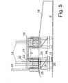
- a hall support 15 is shown, the anchor screws 17 in the support foundation 18 are embedded, which has a metal reinforcement 6.
- Reinforcement 6 the support foundation 18 are both the connecting lugs 31, 32 for the steel structure as well as the connecting tab 21, 22, 23 welded for the adjacent base plate.
- connection flag to the base plate 19 is positioned so that the flexible copper cable 22 comes to lie in the area of the expansion joint and in the adjacent Concrete bodies 18, 19 is concreted in at least 10 cm.
- the associated copper cable 22 leads up to approximately the height of the foundation anchors 16 and then goes into another piece of reinforcing steel 23 of the connecting lug.
- This piece of reinforcing steel 23 extends to the lower limit of the column foundation 18 and is welded there to the metal reinforcement 6 (welding points 10). additionally the piece of reinforcing steel 23 is also welded to the foundation anchor 16 (Welding point 20).
- This terminal lug 21, 22, 23 thus serves the conductive Connection of the base plate 19 to the metal reinforcement 6 of the column foundation 18.
- the supports 15 are grounded via further connecting lugs 31, 32, in which the Copper rope 32 is conductively connected to the support 15.
- the copper cable 32 is in the Supported foundation 18 and only then passes into a piece of reinforcing steel 31, which on the foundation anchor 16 (welding point 20) and on the metal reinforcement 6 (Welds 10) of the support foundation 18 is welded.
- the metal reinforcement of the parapet wall 24 is made using a piece of reinforcing steel 25 conductively connected to the metal reinforcement 6 of the column foundation 18.
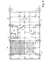
- the hall floor 6 is the hall floor of a production plant with an earthing system according to the invention shown in top view.
- the circumferential parapet wall 24 has a dash-dotted line continuously welded metal reinforcement 6 shown.
- the hall floor exists from individual rectangular plates 34, which by means of connecting tabs 41 for expansion joints (see Fig. 4) are interconnected.
- Over falling or rising earth 1 (represented by lines with a cross) are the systems to be earthed, such as the hall supports 15, with continuously welded metal reinforcements 6 connected.
- the diversions 2 (represented by earthing arrows) can be in the individual Rooms in the hall (transformer room 38, electrical control room 39, hydraulic room 40) Equipotential bonding bars are connected.
- an earthing mesh network smaller than 20x20 m is provided.
- Two of the stage supports 35 of the stage 37 are also connected to the continuously welded earth electrode 1 Reinforcement connected.
- the invention is applicable to all environmental and soil conditions, easy to document and due to the standardized material and the constant Operations can be carried out by the respective construction company without special monitoring.
- connection lugs are welded.
- the copper cable of the connection lug is equipped with the equipment to be earthed (steel structure, equipotential bonding bar, Lightning protection leads etc.) by means of crimped cable lugs and Screws connected.
- connection lugs such as before, but used with copper cables attached to the reinforcing steel on both sides. On In this way, complex welding processes and any type of corrosion can be avoided become.
Landscapes
- Buildings Adapted To Withstand Abnormal External Influences (AREA)
- Reinforcement Elements For Buildings (AREA)
- Coupling Device And Connection With Printed Circuit (AREA)
- Multi-Conductor Connections (AREA)
- Details Of Connecting Devices For Male And Female Coupling (AREA)
- Remote Monitoring And Control Of Power-Distribution Networks (AREA)
- Waveguide Aerials (AREA)
- Connections Effected By Soldering, Adhesion, Or Permanent Deformation (AREA)
Applications Claiming Priority (2)
| Application Number | Priority Date | Filing Date | Title |
|---|---|---|---|
| AT4142002 | 2002-03-19 | ||
| AT0041402A AT411556B (de) | 2002-03-19 | 2002-03-19 | Anschlussfahne und erdungsanlage |
Publications (3)
| Publication Number | Publication Date |
|---|---|
| EP1347534A2 true EP1347534A2 (fr) | 2003-09-24 |
| EP1347534A3 EP1347534A3 (fr) | 2005-07-13 |
| EP1347534B1 EP1347534B1 (fr) | 2007-12-19 |
Family
ID=3673829
Family Applications (1)
| Application Number | Title | Priority Date | Filing Date |
|---|---|---|---|
| EP03003914A Expired - Lifetime EP1347534B1 (fr) | 2002-03-19 | 2003-02-21 | Borne de connexion et dispositif de mise à la terre |
Country Status (3)
| Country | Link |
|---|---|
| EP (1) | EP1347534B1 (fr) |
| AT (2) | AT411556B (fr) |
| DE (1) | DE50308826D1 (fr) |
Cited By (3)
| Publication number | Priority date | Publication date | Assignee | Title |
|---|---|---|---|---|
| CN102694327A (zh) * | 2012-06-06 | 2012-09-26 | 黄岩电力公司 | 10kV开关电缆验电连接线的加工方法 |
| CN105071063A (zh) * | 2015-05-15 | 2015-11-18 | 国家电网公司 | 一种柔性石墨复合接地材料防腐蚀连接方法 |
| WO2020115082A1 (fr) * | 2018-12-03 | 2020-06-11 | Pfeifer Holding Gmbh & Co. Kg | Système de conduction électrique, pièce en béton, procédé et utilisation |
Families Citing this family (2)
| Publication number | Priority date | Publication date | Assignee | Title |
|---|---|---|---|---|
| CN107959137A (zh) * | 2017-12-23 | 2018-04-24 | 河南智金网络技术有限公司 | 一种曲线扁钢强化支撑的接地装置 |
| CN110165434B (zh) * | 2019-06-17 | 2024-01-23 | 中国电建集团西北勘测设计研究院有限公司 | 一种塔式光热电站定日镜桩基础接地装置及其接地方法 |
Family Cites Families (6)
| Publication number | Priority date | Publication date | Assignee | Title |
|---|---|---|---|---|
| US4129744A (en) * | 1976-08-02 | 1978-12-12 | Rca Corporation | Solder connection between copper and aluminum conductors |
| US4361719A (en) * | 1981-03-17 | 1982-11-30 | William Hyde | Earthing systems |
| JPH11122766A (ja) * | 1997-10-15 | 1999-04-30 | Kansai Tech Corp | 電 柱 |
| DE20101302U1 (de) * | 2001-01-25 | 2001-03-29 | Weitkowitz Elektro GmbH, 31224 Peine | Anschlussbuchse für eine Erdungsbrücke |
| DE20101301U1 (de) * | 2001-01-25 | 2001-03-29 | Weitkowitz Elektro GmbH, 31224 Peine | Anschlussbuchse für eine Erdungsbrücke |
| DE20101299U1 (de) * | 2001-01-25 | 2001-04-05 | Weitkowitz Elektro GmbH, 31224 Peine | Anschweißlasche für eine Erdungsbrücke |
-
2002
- 2002-03-19 AT AT0041402A patent/AT411556B/de not_active IP Right Cessation
-
2003
- 2003-02-21 EP EP03003914A patent/EP1347534B1/fr not_active Expired - Lifetime
- 2003-02-21 AT AT03003914T patent/ATE381797T1/de active
- 2003-02-21 DE DE50308826T patent/DE50308826D1/de not_active Expired - Lifetime
Cited By (4)
| Publication number | Priority date | Publication date | Assignee | Title |
|---|---|---|---|---|
| CN102694327A (zh) * | 2012-06-06 | 2012-09-26 | 黄岩电力公司 | 10kV开关电缆验电连接线的加工方法 |
| CN105071063A (zh) * | 2015-05-15 | 2015-11-18 | 国家电网公司 | 一种柔性石墨复合接地材料防腐蚀连接方法 |
| CN105071063B (zh) * | 2015-05-15 | 2017-08-18 | 国家电网公司 | 一种柔性石墨复合接地材料防腐蚀连接方法 |
| WO2020115082A1 (fr) * | 2018-12-03 | 2020-06-11 | Pfeifer Holding Gmbh & Co. Kg | Système de conduction électrique, pièce en béton, procédé et utilisation |
Also Published As
| Publication number | Publication date |
|---|---|
| ATA4142002A (de) | 2003-07-15 |
| AT411556B (de) | 2004-02-25 |
| EP1347534B1 (fr) | 2007-12-19 |
| EP1347534A3 (fr) | 2005-07-13 |
| DE50308826D1 (de) | 2008-01-31 |
| ATE381797T1 (de) | 2008-01-15 |
Similar Documents
| Publication | Publication Date | Title |
|---|---|---|
| DE69425545T2 (de) | Befestigungsklammer | |
| EP0034332A2 (fr) | Elément de construction pour l'isolation thermique de bâtiments | |
| DE202015100183U1 (de) | Schalung für eine Aufkantung | |
| WO1990001570A1 (fr) | Anode de protection anticorrosion cathodique | |
| EP0499590A1 (fr) | Elément connecteur isolant pour planchers de balcon et l'usage de cet élément | |
| AT411556B (de) | Anschlussfahne und erdungsanlage | |
| DE2709114A1 (de) | Verfahren zur herstellung von unterirdischen transportwegen grossen durchmessers | |
| DE102010053998A1 (de) | Vorrichtung und Verfahren zur Mauertrockenlegung | |
| DE19705698B4 (de) | Vorgefertigtes, zwischen eine tragende Gebäudedecke und eine Balkonplattform im Zuge der Betonierung der Gebäudedecke und der Balkonplattform einzubetonierendes Dämmelement | |
| EP3347507B1 (fr) | Procédé de pose d'un système anodique destiné à une protection anticorrosion cathodique | |
| EP0979899B1 (fr) | Elément de support protégé contre la corrosion pour une ancre de sol ou de roche, pieu comprimé ou similaire | |
| EP2725158B1 (fr) | Dispositif de mise à la terre de la fondation d'un bâtiment | |
| CH690966A5 (de) | Isolierendes Anschlusselement für Kragplatten. | |
| EP0522384A1 (fr) | Elément d'ancrage | |
| DE10007067C2 (de) | Am Vertikalstoß von Hohlwandabschnitten stoßüberbrückend ansetzbarer Dichtungsstreifen | |
| DE3343352C1 (de) | Verbundkabel für Spannbetonbauwerke, vorzugsweise für Schrägkabelbrücken | |
| AT406396B (de) | Schalungselement | |
| DE20101302U1 (de) | Anschlussbuchse für eine Erdungsbrücke | |
| EP1873331A2 (fr) | Pylône de ligne électrique aérienne en béton centrifugé | |
| DE10023419C2 (de) | Haltestruktur für eine Rauchabzugsleitung bei einer Dachdurchführung | |
| DE4134232A1 (de) | Korrosionsschutz fuer metallische pfaehle und verpressanker | |
| DE10156291B4 (de) | Vorrichtung zur Fixierung von Hausanschlussleitungen | |
| DE102017114928B4 (de) | Umspannwerkvorrichtung sowie Verfahren zur Herstellung derselbigen | |
| DE4023695C2 (de) | Vorrichtung zum Verlegen von aus Rohren bestehenden Kanalleitungen, insbesondere Abwasserkanalleitungen | |
| DE3504942A1 (de) | Verfahren zur befestigung eines verankerungsstabs in einem waermedaemmenden isolierkoerper und isolierkoerper zur aufnahme eines verankerungsstabs |
Legal Events
| Date | Code | Title | Description |
|---|---|---|---|
| PUAI | Public reference made under article 153(3) epc to a published international application that has entered the european phase |
Free format text: ORIGINAL CODE: 0009012 |
|
| AK | Designated contracting states |
Kind code of ref document: A2 Designated state(s): AT BE BG CH CY CZ DE DK EE ES FI FR GB GR HU IE IT LI LU MC NL PT SE SI SK TR |
|
| AX | Request for extension of the european patent |
Extension state: AL LT LV MK RO |
|
| PUAL | Search report despatched |
Free format text: ORIGINAL CODE: 0009013 |
|
| AK | Designated contracting states |
Kind code of ref document: A3 Designated state(s): AT BE BG CH CY CZ DE DK EE ES FI FR GB GR HU IE IT LI LU MC NL PT SE SI SK TR |
|
| AX | Request for extension of the european patent |
Extension state: AL LT LV MK RO |
|
| RIC1 | Information provided on ipc code assigned before grant |
Ipc: 7H 01R 4/66 B Ipc: 7H 01R 4/64 A Ipc: 7H 01R 4/62 B |
|
| 17P | Request for examination filed |
Effective date: 20051213 |
|
| AKX | Designation fees paid |
Designated state(s): AT BE BG CH CY CZ DE DK EE ES FI FR GB GR HU IE IT LI LU MC NL PT SE SI SK TR |
|
| GRAP | Despatch of communication of intention to grant a patent |
Free format text: ORIGINAL CODE: EPIDOSNIGR1 |
|
| RAP1 | Party data changed (applicant data changed or rights of an application transferred) |
Owner name: SIEMENS VAI METALS TECHNOLOGIES GMBH & CO |
|
| GRAS | Grant fee paid |
Free format text: ORIGINAL CODE: EPIDOSNIGR3 |
|
| GRAA | (expected) grant |
Free format text: ORIGINAL CODE: 0009210 |
|
| AK | Designated contracting states |
Kind code of ref document: B1 Designated state(s): AT BE BG CH CY CZ DE DK EE ES FI FR GB GR HU IE IT LI LU MC NL PT SE SI SK TR |
|
| REG | Reference to a national code |
Ref country code: GB Ref legal event code: FG4D Free format text: NOT ENGLISH |
|
| REG | Reference to a national code |
Ref country code: IE Ref legal event code: FG4D Free format text: LANGUAGE OF EP DOCUMENT: GERMAN |
|
| REG | Reference to a national code |
Ref country code: CH Ref legal event code: EP |
|
| REF | Corresponds to: |
Ref document number: 50308826 Country of ref document: DE Date of ref document: 20080131 Kind code of ref document: P |
|
| GBT | Gb: translation of ep patent filed (gb section 77(6)(a)/1977) |
Effective date: 20080313 |
|
| PG25 | Lapsed in a contracting state [announced via postgrant information from national office to epo] |
Ref country code: SE Free format text: LAPSE BECAUSE OF FAILURE TO SUBMIT A TRANSLATION OF THE DESCRIPTION OR TO PAY THE FEE WITHIN THE PRESCRIBED TIME-LIMIT Effective date: 20080319 |
|
| PG25 | Lapsed in a contracting state [announced via postgrant information from national office to epo] |
Ref country code: FI Free format text: LAPSE BECAUSE OF FAILURE TO SUBMIT A TRANSLATION OF THE DESCRIPTION OR TO PAY THE FEE WITHIN THE PRESCRIBED TIME-LIMIT Effective date: 20071219 Ref country code: SI Free format text: LAPSE BECAUSE OF FAILURE TO SUBMIT A TRANSLATION OF THE DESCRIPTION OR TO PAY THE FEE WITHIN THE PRESCRIBED TIME-LIMIT Effective date: 20071219 |
|
| PG25 | Lapsed in a contracting state [announced via postgrant information from national office to epo] |
Ref country code: ES Free format text: LAPSE BECAUSE OF FAILURE TO SUBMIT A TRANSLATION OF THE DESCRIPTION OR TO PAY THE FEE WITHIN THE PRESCRIBED TIME-LIMIT Effective date: 20080330 |
|
| ET | Fr: translation filed | ||
| PG25 | Lapsed in a contracting state [announced via postgrant information from national office to epo] |
Ref country code: PT Free format text: LAPSE BECAUSE OF FAILURE TO SUBMIT A TRANSLATION OF THE DESCRIPTION OR TO PAY THE FEE WITHIN THE PRESCRIBED TIME-LIMIT Effective date: 20080519 |
|
| REG | Reference to a national code |
Ref country code: CH Ref legal event code: PL |
|
| REG | Reference to a national code |
Ref country code: IE Ref legal event code: FD4D |
|
| PLBE | No opposition filed within time limit |
Free format text: ORIGINAL CODE: 0009261 |
|
| STAA | Information on the status of an ep patent application or granted ep patent |
Free format text: STATUS: NO OPPOSITION FILED WITHIN TIME LIMIT |
|
| PG25 | Lapsed in a contracting state [announced via postgrant information from national office to epo] |
Ref country code: DK Free format text: LAPSE BECAUSE OF FAILURE TO SUBMIT A TRANSLATION OF THE DESCRIPTION OR TO PAY THE FEE WITHIN THE PRESCRIBED TIME-LIMIT Effective date: 20071219 Ref country code: CH Free format text: LAPSE BECAUSE OF NON-PAYMENT OF DUE FEES Effective date: 20080229 Ref country code: IE Free format text: LAPSE BECAUSE OF FAILURE TO SUBMIT A TRANSLATION OF THE DESCRIPTION OR TO PAY THE FEE WITHIN THE PRESCRIBED TIME-LIMIT Effective date: 20071219 Ref country code: MC Free format text: LAPSE BECAUSE OF NON-PAYMENT OF DUE FEES Effective date: 20080228 Ref country code: LI Free format text: LAPSE BECAUSE OF NON-PAYMENT OF DUE FEES Effective date: 20080229 |
|
| 26N | No opposition filed |
Effective date: 20080922 |
|
| PG25 | Lapsed in a contracting state [announced via postgrant information from national office to epo] |
Ref country code: EE Free format text: LAPSE BECAUSE OF FAILURE TO SUBMIT A TRANSLATION OF THE DESCRIPTION OR TO PAY THE FEE WITHIN THE PRESCRIBED TIME-LIMIT Effective date: 20071219 Ref country code: GR Free format text: LAPSE BECAUSE OF FAILURE TO SUBMIT A TRANSLATION OF THE DESCRIPTION OR TO PAY THE FEE WITHIN THE PRESCRIBED TIME-LIMIT Effective date: 20080320 |
|
| PG25 | Lapsed in a contracting state [announced via postgrant information from national office to epo] |
Ref country code: BG Free format text: LAPSE BECAUSE OF FAILURE TO SUBMIT A TRANSLATION OF THE DESCRIPTION OR TO PAY THE FEE WITHIN THE PRESCRIBED TIME-LIMIT Effective date: 20080319 |
|
| PG25 | Lapsed in a contracting state [announced via postgrant information from national office to epo] |
Ref country code: CY Free format text: LAPSE BECAUSE OF FAILURE TO SUBMIT A TRANSLATION OF THE DESCRIPTION OR TO PAY THE FEE WITHIN THE PRESCRIBED TIME-LIMIT Effective date: 20071219 |
|
| PG25 | Lapsed in a contracting state [announced via postgrant information from national office to epo] |
Ref country code: LU Free format text: LAPSE BECAUSE OF NON-PAYMENT OF DUE FEES Effective date: 20080221 Ref country code: HU Free format text: LAPSE BECAUSE OF FAILURE TO SUBMIT A TRANSLATION OF THE DESCRIPTION OR TO PAY THE FEE WITHIN THE PRESCRIBED TIME-LIMIT Effective date: 20080620 |
|
| PG25 | Lapsed in a contracting state [announced via postgrant information from national office to epo] |
Ref country code: TR Free format text: LAPSE BECAUSE OF FAILURE TO SUBMIT A TRANSLATION OF THE DESCRIPTION OR TO PAY THE FEE WITHIN THE PRESCRIBED TIME-LIMIT Effective date: 20071219 |
|
| PG25 | Lapsed in a contracting state [announced via postgrant information from national office to epo] |
Ref country code: IT Free format text: LAPSE BECAUSE OF NON-PAYMENT OF DUE FEES Effective date: 20100221 |
|
| PGFP | Annual fee paid to national office [announced via postgrant information from national office to epo] |
Ref country code: IT Payment date: 20120222 Year of fee payment: 10 |
|
| PGFP | Annual fee paid to national office [announced via postgrant information from national office to epo] |
Ref country code: CZ Payment date: 20130214 Year of fee payment: 11 Ref country code: GB Payment date: 20130213 Year of fee payment: 11 Ref country code: FR Payment date: 20130301 Year of fee payment: 11 |
|
| PGFP | Annual fee paid to national office [announced via postgrant information from national office to epo] |
Ref country code: NL Payment date: 20130204 Year of fee payment: 11 Ref country code: SK Payment date: 20130221 Year of fee payment: 11 |
|
| PGFP | Annual fee paid to national office [announced via postgrant information from national office to epo] |
Ref country code: BE Payment date: 20130312 Year of fee payment: 11 |
|
| BERE | Be: lapsed |
Owner name: SIEMENS VAI METALS TECHNOLOGIES GMBH & CO Effective date: 20140228 |
|
| REG | Reference to a national code |
Ref country code: NL Ref legal event code: V1 Effective date: 20140901 |
|
| GBPC | Gb: european patent ceased through non-payment of renewal fee |
Effective date: 20140221 |
|
| PG25 | Lapsed in a contracting state [announced via postgrant information from national office to epo] |
Ref country code: NL Free format text: LAPSE BECAUSE OF NON-PAYMENT OF DUE FEES Effective date: 20140901 Ref country code: CZ Free format text: LAPSE BECAUSE OF NON-PAYMENT OF DUE FEES Effective date: 20140221 |
|
| REG | Reference to a national code |
Ref country code: SK Ref legal event code: MM4A Ref document number: E 3099 Country of ref document: SK Effective date: 20140221 |
|
| REG | Reference to a national code |
Ref country code: FR Ref legal event code: ST Effective date: 20141031 |
|
| PG25 | Lapsed in a contracting state [announced via postgrant information from national office to epo] |
Ref country code: SK Free format text: LAPSE BECAUSE OF NON-PAYMENT OF DUE FEES Effective date: 20140221 |
|
| PG25 | Lapsed in a contracting state [announced via postgrant information from national office to epo] |
Ref country code: GB Free format text: LAPSE BECAUSE OF NON-PAYMENT OF DUE FEES Effective date: 20140221 Ref country code: FR Free format text: LAPSE BECAUSE OF NON-PAYMENT OF DUE FEES Effective date: 20140228 Ref country code: BE Free format text: LAPSE BECAUSE OF NON-PAYMENT OF DUE FEES Effective date: 20140228 |
|
| PG25 | Lapsed in a contracting state [announced via postgrant information from national office to epo] |
Ref country code: IT Free format text: LAPSE BECAUSE OF NON-PAYMENT OF DUE FEES Effective date: 20140221 |
|
| REG | Reference to a national code |
Ref country code: DE Ref legal event code: R082 Ref document number: 50308826 Country of ref document: DE Representative=s name: KINNSTAETTER, KLAUS, DIPL.-PHYS.UNIV., DE |
|
| REG | Reference to a national code |
Ref country code: DE Ref legal event code: R082 Ref document number: 50308826 Country of ref document: DE Representative=s name: KINNSTAETTER, KLAUS, DIPL.-PHYS.UNIV., DE Ref country code: DE Ref legal event code: R081 Ref document number: 50308826 Country of ref document: DE Owner name: PRIMETALS TECHNOLOGIES AUSTRIA GMBH, AT Free format text: FORMER OWNER: SIEMENS VAI METALS TECHNOLOGIES GMBH & CO. KG, LINZ, AT |
|
| REG | Reference to a national code |
Ref country code: AT Ref legal event code: PC Ref document number: 381797 Country of ref document: AT Kind code of ref document: T Owner name: PRIMETALS TECHNOLOGIES AUSTRIA GMBH, AT Effective date: 20170201 |
|
| PGFP | Annual fee paid to national office [announced via postgrant information from national office to epo] |
Ref country code: AT Payment date: 20200220 Year of fee payment: 18 Ref country code: DE Payment date: 20200219 Year of fee payment: 18 |
|
| REG | Reference to a national code |
Ref country code: DE Ref legal event code: R119 Ref document number: 50308826 Country of ref document: DE |
|
| REG | Reference to a national code |
Ref country code: AT Ref legal event code: MM01 Ref document number: 381797 Country of ref document: AT Kind code of ref document: T Effective date: 20210221 |
|
| PG25 | Lapsed in a contracting state [announced via postgrant information from national office to epo] |
Ref country code: AT Free format text: LAPSE BECAUSE OF NON-PAYMENT OF DUE FEES Effective date: 20210221 |
|
| PG25 | Lapsed in a contracting state [announced via postgrant information from national office to epo] |
Ref country code: DE Free format text: LAPSE BECAUSE OF NON-PAYMENT OF DUE FEES Effective date: 20210901 |