EP1347534B1 - Borne de connexion et dispositif de mise à la terre - Google Patents
Borne de connexion et dispositif de mise à la terre Download PDFInfo
- Publication number
- EP1347534B1 EP1347534B1 EP03003914A EP03003914A EP1347534B1 EP 1347534 B1 EP1347534 B1 EP 1347534B1 EP 03003914 A EP03003914 A EP 03003914A EP 03003914 A EP03003914 A EP 03003914A EP 1347534 B1 EP1347534 B1 EP 1347534B1
- Authority
- EP
- European Patent Office
- Prior art keywords
- reinforcing steel
- connecting lug
- concrete
- welded
- earthing
- Prior art date
- Legal status (The legal status is an assumption and is not a legal conclusion. Google has not performed a legal analysis and makes no representation as to the accuracy of the status listed.)
- Expired - Lifetime
Links
- 229910001294 Reinforcing steel Inorganic materials 0.000 claims abstract description 40
- 230000002787 reinforcement Effects 0.000 claims abstract description 24
- RYGMFSIKBFXOCR-UHFFFAOYSA-N Copper Chemical compound [Cu] RYGMFSIKBFXOCR-UHFFFAOYSA-N 0.000 claims abstract description 21
- 229910052802 copper Inorganic materials 0.000 claims abstract description 18
- 239000010949 copper Substances 0.000 claims abstract description 18
- 239000004020 conductor Substances 0.000 claims abstract description 11
- 238000004519 manufacturing process Methods 0.000 claims abstract description 5
- 238000009434 installation Methods 0.000 claims description 12
- 229910000831 Steel Inorganic materials 0.000 abstract description 7
- 239000010959 steel Substances 0.000 abstract description 7
- 238000003466 welding Methods 0.000 abstract description 7
- 239000002184 metal Substances 0.000 description 10
- 229910052751 metal Inorganic materials 0.000 description 10
- 230000003014 reinforcing effect Effects 0.000 description 7
- 238000000034 method Methods 0.000 description 6
- 238000005260 corrosion Methods 0.000 description 5
- 230000007797 corrosion Effects 0.000 description 5
- 238000005219 brazing Methods 0.000 description 4
- 238000010276 construction Methods 0.000 description 4
- 230000015572 biosynthetic process Effects 0.000 description 3
- 239000000463 material Substances 0.000 description 3
- XEEYBQQBJWHFJM-UHFFFAOYSA-N Iron Chemical compound [Fe] XEEYBQQBJWHFJM-UHFFFAOYSA-N 0.000 description 2
- 238000013461 design Methods 0.000 description 2
- 230000007704 transition Effects 0.000 description 2
- 238000007792 addition Methods 0.000 description 1
- 238000007796 conventional method Methods 0.000 description 1
- 230000007613 environmental effect Effects 0.000 description 1
- 229910052742 iron Inorganic materials 0.000 description 1
- 238000005304 joining Methods 0.000 description 1
- 238000012544 monitoring process Methods 0.000 description 1
- 230000002093 peripheral effect Effects 0.000 description 1
- 238000003672 processing method Methods 0.000 description 1
- 230000000630 rising effect Effects 0.000 description 1
- 239000002689 soil Substances 0.000 description 1
Images



Classifications
-
- H—ELECTRICITY
- H01—ELECTRIC ELEMENTS
- H01R—ELECTRICALLY-CONDUCTIVE CONNECTIONS; STRUCTURAL ASSOCIATIONS OF A PLURALITY OF MUTUALLY-INSULATED ELECTRICAL CONNECTING ELEMENTS; COUPLING DEVICES; CURRENT COLLECTORS
- H01R4/00—Electrically-conductive connections between two or more conductive members in direct contact, i.e. touching one another; Means for effecting or maintaining such contact; Electrically-conductive connections having two or more spaced connecting locations for conductors and using contact members penetrating insulation
- H01R4/58—Electrically-conductive connections between two or more conductive members in direct contact, i.e. touching one another; Means for effecting or maintaining such contact; Electrically-conductive connections having two or more spaced connecting locations for conductors and using contact members penetrating insulation characterised by the form or material of the contacting members
- H01R4/66—Connections with the terrestrial mass, e.g. earth plate, earth pin
-
- H—ELECTRICITY
- H01—ELECTRIC ELEMENTS
- H01R—ELECTRICALLY-CONDUCTIVE CONNECTIONS; STRUCTURAL ASSOCIATIONS OF A PLURALITY OF MUTUALLY-INSULATED ELECTRICAL CONNECTING ELEMENTS; COUPLING DEVICES; CURRENT COLLECTORS
- H01R4/00—Electrically-conductive connections between two or more conductive members in direct contact, i.e. touching one another; Means for effecting or maintaining such contact; Electrically-conductive connections having two or more spaced connecting locations for conductors and using contact members penetrating insulation
- H01R4/58—Electrically-conductive connections between two or more conductive members in direct contact, i.e. touching one another; Means for effecting or maintaining such contact; Electrically-conductive connections having two or more spaced connecting locations for conductors and using contact members penetrating insulation characterised by the form or material of the contacting members
- H01R4/62—Connections between conductors of different materials; Connections between or with aluminium or steel-core aluminium conductors
- H01R4/625—Soldered or welded connections
Definitions
- the present invention relates to a terminal lug for the conductive connection of installations to reinforcing steel cast in concrete for the purpose of grounding, to a corresponding grounding system and to a method for producing a grounding system.
- a Flexible terminal lugs which consist of a copper conductor, welded to a sleeve and this sleeve with a bar of the reinforcement.
- the welding of the copper conductor with the sleeve is done using the complex CADWELD method, which can only be performed by specially trained personnel.
- Terminals are used to connect ground wires and reinforcing bars together.
- connecting copper grounding wires to the reinforcing bars can cause galvanic element formation and therefore corrosion.
- the use of an insulated conductor can not cause corrosion at the transition between concrete and air.
- connection lug can simply be welded to the reinforcing steel without special welding procedures, no specially trained personnel is required for this purpose.
- the welding of the terminal lugs can be advantageously carried out by the construction company, which manufactures the reinforcement.
- a particularly simple solution for producing the terminal lug is to connect the piece of reinforcing steel and the conductor by brazing or notches by means of a notched sleeve with each other.
- Reinforcing steel used is bare, hot-rolled reinforcing steel. This reinforcing steel does not corrode in concrete and is therefore well suited for grounding purposes (as a grounding network). Due to the relatively good conductivity of concrete (about 250 ohm m), the - in foundations - very large concrete surfaces and embedded therein bars of reinforcing steel, the so-called "natural earth” in large quantity or length is required for grounding propagation resistance easy to reach and given the required potential control automatically. The sole use of steel in concrete eliminates any galvanic element formation from the outset.
- the design of the basic earthing network is carried out with regard to the maximum thermal load in the event of a fault and to the permissible contact voltages at the earthing system.
- the design of grounding systems is familiar to the person skilled in the art and will not be discussed further here.
- the required propagation resistance is achieved by deliberate concreting in of additional reinforcing steel in the foundations. This can e.g. in areas where very high ground fault currents can occur (switchgear, outdoor switchgear, ...) are used.
- the connecting lug according to FIG. 1 consists of a piece of bare reinforcing steel 1 with a diameter of at least 10 mm and a length of approx. 2 m as well as one piece of insulated copper rope 2 with a cross section of approx. 95 mm 2 and likewise a length of approx 2 m. Cross-section and lengths are to be adapted to the respective requirements.
- the reinforcing steel and the copper rope are connected by means of a notched sleeve 3 made of copper: the reinforcing steel is connected to the notch sleeve by brazing (brazing 4), the copper rope is notched.
- the notched sleeve is surrounded by a shrink tube 5 beyond its ends.
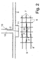
- Fig. 2 shows how the reinforcing bars 6, which have a length of at least 5 m and a diameter of at least 10 mm, are connected to each other mainly by Rödelharmen 7.
- Rödel2000 are approved as earth connections.
- the Rödeltechen serve on the one hand to produce longitudinal reinforcements 8 with a greater length than that of a reinforcing bar 6, on the other hand thereby the mutually perpendicular longitudinal reinforcements are connected together.
- the individual reinforcing rods are welded together for reasons of better conductivity (black mark in Fig. 2).
- the individual welds have a length of about 5 cm.
- one of the longitudinal reinforcements is to be welded continuously.
- the reinforcing steel 1 of the connecting lug is welded to the continuously welded reinforcing bars at least three places 10 over a length of about 5 cm.
- the terminal lug including the notched sleeve 3 is also poured into concrete.
- the notch sleeve should then be at least about 10 cm below the concrete surface.
- the terminal lugs are generally arranged so that the loose end of the copper rope as close to the plant to be grounded (hall support, equipotential bonding rail and the like) is led out with an excess length of about 1 m.
- the copper cable 2 has at the end of a pressed-cable lug and is guided in Fig. 2 approximately to a building wall 12 and screwed to a potential equalization rail 13 arranged there made of copper.
- a connecting lug for expansion joints which serves to connect two to be ground construction parts, that is about two separate by an expansion joint floor panels, conductively connected to each other.
- a 2 m long piece of reinforcing steel 1 is attached to an approximately 1 m long copper cable 2 with 95 mm 2 cross-sectional area at both ends by means of notched sleeves 3 and brazing 4, as already described in Fig. 1.
- the notched sleeves are in turn surrounded by a shrink tube 5.
- Fig. 4 shows how the connecting lug 1, 2 on two reinforcing bars of each longitudinally welded longitudinal reinforcement 9 of e.g. two adjacent floor panels are welded to both sides of the expansion joint 14.
- This connection lug is not only suitable for expansion joints, but generally for joining metal-reinforced components.
- a hall support 15 is shown, the anchor bolts 17 are embedded in the pillar foundation 18, which has a metal reinforcement 6.
- connecting lug is positioned to the bottom plate 19 so that the flexible copper rope 22 comes to lie in the region of the expansion joint and in the adjacent concrete bodies 18, 19 at least 10 cm is embedded in concrete.
- the associated copper cable 22 leads to about the height of the foundation anchor 16 and then goes back to another piece of reinforcing steel 23 of the connection lug.
- This piece of reinforcing steel 23 extends to the lower boundary of the support foundation 18 and is there welded to the metal reinforcement 6 (welds 10).
- the piece of reinforcing steel 23 is also welded to the foundation anchor 16 (weld 20).
- This terminal lug 21, 22, 23 thus serves the conductive connection of the bottom plate 19 with the metal reinforcement 6 of the support foundation 18th
- the copper cable 32 is guided into the support foundation 18 and only there transitions into a piece of reinforcing steel 31, which is welded to the foundation anchor 16 (welding point 20) and to the metal reinforcement 6 (welds 10) of the support foundation 18.
- the metal reinforcement of the parapet wall 24 is conductively connected to the metal reinforcement 6 of the support foundation 18 via a piece of reinforcing steel 25.
- Fig. 6 the hall floor of a production plant with inventive grounding system is shown in plan view.
- the peripheral Parapetwand 24 has a dash-dotted lines continuously welded metal reinforcement 6.
- the hall floor consists of individual rectangular plates 34 which are interconnected by means of connecting lugs 41 for expansion joints (see FIG. 4).
- In the hall floor are also shown dash-dotted continuously welded metal reinforcements arranged.
- About falling or rising earth electrode 1 (represented by lines with cross) are connected to ground systems, such as the hall supports 15, with continuously welded metal reinforcements 6.
- the spouts 2 (represented by grounding arrows) can be connected to equipotential busbars in the individual rooms of the hall (transformer room 38, electrical control room 39, hydraulic room 40).
- a grounding mesh net smaller 20x20 m is provided in the indoor area 36, shown in dashed lines.
- Two of the stage supports 35 of the stage 37 are also connected via earth electrode 1 with the continuously welded reinforcement.
- the invention is applicable to all environmental conditions and soil conditions, easy to document and due to the standardized material and the consistent operations by the respective construction company without special monitoring feasible.
- connection lugs are used as before, but with copper cables attached to both sides of the reinforcing steel. On This way, elaborate welding processes and any kind of corrosion can be avoided.
Landscapes
- Buildings Adapted To Withstand Abnormal External Influences (AREA)
- Reinforcement Elements For Buildings (AREA)
- Coupling Device And Connection With Printed Circuit (AREA)
- Multi-Conductor Connections (AREA)
- Details Of Connecting Devices For Male And Female Coupling (AREA)
- Connections Effected By Soldering, Adhesion, Or Permanent Deformation (AREA)
- Remote Monitoring And Control Of Power-Distribution Networks (AREA)
- Waveguide Aerials (AREA)
Claims (8)
- Borne de connexion préfabriquée pour la liaison conductrice d'installations à une armature en acier (6) noyée dans du béton, pour les mettre à la terre, caractérisée en ce que la borne de connexion est composée d'au moins un morceau d'acier d'armature en forme de barre (1, 21, 23, 31), qui peut être soudé à l'acier d'armature (6) noyé dans le béton, et d'au moins un conducteur isolé flexible, comme un câble de cuivre (2, 22, 32), qui peut être raccordé à l'installation.
- Borne de connexion selon la revendication 1 pour franchir des joints de dilatation, caractérisée en ce que le conducteur (2, 22) est relié à chacune de ses deux extrémités à un morceau d'acier d'armature (1; 21, 23).
- Borne de connexion selon l'une quelconque des revendications 1 ou 2, caractérisée en ce que l'acier d'armature (1, 21, 23, 31) et le conducteur (2, 22, 32) sont assemblés l'un à l'autre par un manchon d'entaillage (3).
- Borne de connexion selon la revendication 3, caractérisée en ce que l'acier d'armature (1, 21, 23, 31) est assemblé au manchon d'entaillage (3) par une brasure dure (4).
- Borne de connexion selon la revendication 3 ou 4, caractérisée en ce que le manchon d'entaillage (3) est enveloppé d'une gaine rétractable (5) pour assurer une protection supplémentaire contre l'humidité.
- Dispositif de mise à la terre, comprenant un acier d'armature (6, 8, 9) noyé dans le béton, auquel au moins une borne de connexion préfabriquée est soudée pour assurer une liaison conductrice entre des installations mises à la terre et des installations à mettre à la terre ou entre des installations à mettre à la terre ou des installations mises à la terre entre elles, caractérisé en ce qu'au moins une borne de connexion réalisée selon l'une quelconque des revendications 1 à 5 et le morceau d'acier d'armature (1, 21, 23, 31) sont soudés à l'acier d'armature (9) noyé dans le béton.
- Dispositif de mise à la terre selon la revendication 6, caractérisé en ce que le manchon d'entaillage (3) reliant le morceau d'acier d'armature (1, 21, 23, 31) au conducteur (2, 22, 32) est également noyé dans le béton.
- Procédé pour réaliser un dispositif de mise à la terre selon la revendication 6 ou 7, caractérisé
en ce que l'acier d'armature (6, 8, 9) est, selon sa fonction, posé et relié comme armature et comme partie du dispositif de mise à la terre,
en ce qu'au moins une borne de connexion préfabriquée selon l'une quelconque des revendications 1 à 5 est soudée à l'acier d'armature (9), et
en ce que l'acier d'armature (6, 8, 9) et le point de soudure (10), où la borne de connexion est soudée à l'acier d'armature, est noyé dans le béton.
Applications Claiming Priority (2)
| Application Number | Priority Date | Filing Date | Title |
|---|---|---|---|
| AT0041402A AT411556B (de) | 2002-03-19 | 2002-03-19 | Anschlussfahne und erdungsanlage |
| AT4142002 | 2002-03-19 |
Publications (3)
| Publication Number | Publication Date |
|---|---|
| EP1347534A2 EP1347534A2 (fr) | 2003-09-24 |
| EP1347534A3 EP1347534A3 (fr) | 2005-07-13 |
| EP1347534B1 true EP1347534B1 (fr) | 2007-12-19 |
Family
ID=3673829
Family Applications (1)
| Application Number | Title | Priority Date | Filing Date |
|---|---|---|---|
| EP03003914A Expired - Lifetime EP1347534B1 (fr) | 2002-03-19 | 2003-02-21 | Borne de connexion et dispositif de mise à la terre |
Country Status (3)
| Country | Link |
|---|---|
| EP (1) | EP1347534B1 (fr) |
| AT (2) | AT411556B (fr) |
| DE (1) | DE50308826D1 (fr) |
Cited By (1)
| Publication number | Priority date | Publication date | Assignee | Title |
|---|---|---|---|---|
| CN113169462A (zh) * | 2018-12-03 | 2021-07-23 | 法尔福控股合资有限公司 | 导电布置结构、混凝土构件、方法和用途 |
Families Citing this family (4)
| Publication number | Priority date | Publication date | Assignee | Title |
|---|---|---|---|---|
| CN102694327B (zh) * | 2012-06-06 | 2014-04-16 | 黄岩电力公司 | 10kV开关电缆验电连接线的加工方法 |
| CN105071063B (zh) * | 2015-05-15 | 2017-08-18 | 国家电网公司 | 一种柔性石墨复合接地材料防腐蚀连接方法 |
| CN107959137A (zh) * | 2017-12-23 | 2018-04-24 | 河南智金网络技术有限公司 | 一种曲线扁钢强化支撑的接地装置 |
| CN110165434B (zh) * | 2019-06-17 | 2024-01-23 | 中国电建集团西北勘测设计研究院有限公司 | 一种塔式光热电站定日镜桩基础接地装置及其接地方法 |
Family Cites Families (6)
| Publication number | Priority date | Publication date | Assignee | Title |
|---|---|---|---|---|
| US4129744A (en) * | 1976-08-02 | 1978-12-12 | Rca Corporation | Solder connection between copper and aluminum conductors |
| US4361719A (en) * | 1981-03-17 | 1982-11-30 | William Hyde | Earthing systems |
| JPH11122766A (ja) * | 1997-10-15 | 1999-04-30 | Kansai Tech Corp | 電 柱 |
| DE20101302U1 (de) * | 2001-01-25 | 2001-03-29 | Weitkowitz Elektro GmbH, 31224 Peine | Anschlussbuchse für eine Erdungsbrücke |
| DE20101301U1 (de) * | 2001-01-25 | 2001-03-29 | Weitkowitz Elektro GmbH, 31224 Peine | Anschlussbuchse für eine Erdungsbrücke |
| DE20101299U1 (de) * | 2001-01-25 | 2001-04-05 | Weitkowitz Elektro GmbH, 31224 Peine | Anschweißlasche für eine Erdungsbrücke |
-
2002
- 2002-03-19 AT AT0041402A patent/AT411556B/de not_active IP Right Cessation
-
2003
- 2003-02-21 AT AT03003914T patent/ATE381797T1/de active
- 2003-02-21 EP EP03003914A patent/EP1347534B1/fr not_active Expired - Lifetime
- 2003-02-21 DE DE50308826T patent/DE50308826D1/de not_active Expired - Lifetime
Cited By (1)
| Publication number | Priority date | Publication date | Assignee | Title |
|---|---|---|---|---|
| CN113169462A (zh) * | 2018-12-03 | 2021-07-23 | 法尔福控股合资有限公司 | 导电布置结构、混凝土构件、方法和用途 |
Also Published As
| Publication number | Publication date |
|---|---|
| EP1347534A3 (fr) | 2005-07-13 |
| ATE381797T1 (de) | 2008-01-15 |
| AT411556B (de) | 2004-02-25 |
| ATA4142002A (de) | 2003-07-15 |
| EP1347534A2 (fr) | 2003-09-24 |
| DE50308826D1 (de) | 2008-01-31 |
Similar Documents
| Publication | Publication Date | Title |
|---|---|---|
| EP0338972B1 (fr) | Elément de raccordement pour panneau en porte-à-faux | |
| WO1990001570A1 (fr) | Anode de protection anticorrosion cathodique | |
| DE102015121810A1 (de) | Schalung für eine Aufkantung | |
| EP0499590A1 (fr) | Elément connecteur isolant pour planchers de balcon et l'usage de cet élément | |
| EP1347534B1 (fr) | Borne de connexion et dispositif de mise à la terre | |
| DE19652165A1 (de) | Fertigbauteil für eine auskragende Balkonplatte | |
| EP4067593A1 (fr) | Dispositif de liaison ultérieure à isolation thermique et à transfert de force d'une seconde partie d'ouvrage supportant la charge à une première partie d'ouvrage supportant la charge et ouvrage doté d'un tel dispositif | |
| EP2725158B1 (fr) | Dispositif de mise à la terre de la fondation d'un bâtiment | |
| DE3328070A1 (de) | Bauelement zur waermedaemmung bei gebaeuden | |
| EP0947640B1 (fr) | Armature à haute adhérence | |
| DE102016106290A1 (de) | Bewehrungselement | |
| DE4134232A1 (de) | Korrosionsschutz fuer metallische pfaehle und verpressanker | |
| DE10156291B4 (de) | Vorrichtung zur Fixierung von Hausanschlussleitungen | |
| EP0278214A2 (fr) | Arrangement pour chauffer un plancher | |
| EP0796961A1 (fr) | Système d'armature pour éléments en béton cellulaire | |
| EP3709463A1 (fr) | Coupe-feu et procédé de fabrication de coupe-feu étanche à la fumée à sollicitation mécanique en cas d'incendie | |
| DE102011056967A1 (de) | Plattenanschlusselement | |
| EP1148179A1 (fr) | Elément structurel de raccord thermo-isolant et ignifuge pour raccorder un élément porteur à un élément porté et méthode de connexion | |
| EP0006567A1 (fr) | Elément chauffant servant au chauffage de marches d'escalier, de planchers, d'éléments en béton etc. | |
| DE1615608B2 (de) | Vorrichtung zur Masseverbindung an Holz- Tragkonstruktionen | |
| DE3406664A1 (de) | Kabelkanal | |
| DE19643874A1 (de) | Isoliertes Metallrohr | |
| DE4430759A1 (de) | Verfahren und Vorrichtung zum Auswechseln eines Mastkopfes eines Winkeltragmastes einer Hochspannungsfreileitung | |
| DE1963946U (de) | Verbundanker fuer fertigwandelemente aus stahlbeton. | |
| DE2121503A1 (de) | Umschlossene Gebäudeeinheit |
Legal Events
| Date | Code | Title | Description |
|---|---|---|---|
| PUAI | Public reference made under article 153(3) epc to a published international application that has entered the european phase |
Free format text: ORIGINAL CODE: 0009012 |
|
| AK | Designated contracting states |
Kind code of ref document: A2 Designated state(s): AT BE BG CH CY CZ DE DK EE ES FI FR GB GR HU IE IT LI LU MC NL PT SE SI SK TR |
|
| AX | Request for extension of the european patent |
Extension state: AL LT LV MK RO |
|
| PUAL | Search report despatched |
Free format text: ORIGINAL CODE: 0009013 |
|
| AK | Designated contracting states |
Kind code of ref document: A3 Designated state(s): AT BE BG CH CY CZ DE DK EE ES FI FR GB GR HU IE IT LI LU MC NL PT SE SI SK TR |
|
| AX | Request for extension of the european patent |
Extension state: AL LT LV MK RO |
|
| RIC1 | Information provided on ipc code assigned before grant |
Ipc: 7H 01R 4/66 B Ipc: 7H 01R 4/64 A Ipc: 7H 01R 4/62 B |
|
| 17P | Request for examination filed |
Effective date: 20051213 |
|
| AKX | Designation fees paid |
Designated state(s): AT BE BG CH CY CZ DE DK EE ES FI FR GB GR HU IE IT LI LU MC NL PT SE SI SK TR |
|
| GRAP | Despatch of communication of intention to grant a patent |
Free format text: ORIGINAL CODE: EPIDOSNIGR1 |
|
| RAP1 | Party data changed (applicant data changed or rights of an application transferred) |
Owner name: SIEMENS VAI METALS TECHNOLOGIES GMBH & CO |
|
| GRAS | Grant fee paid |
Free format text: ORIGINAL CODE: EPIDOSNIGR3 |
|
| GRAA | (expected) grant |
Free format text: ORIGINAL CODE: 0009210 |
|
| AK | Designated contracting states |
Kind code of ref document: B1 Designated state(s): AT BE BG CH CY CZ DE DK EE ES FI FR GB GR HU IE IT LI LU MC NL PT SE SI SK TR |
|
| REG | Reference to a national code |
Ref country code: GB Ref legal event code: FG4D Free format text: NOT ENGLISH |
|
| REG | Reference to a national code |
Ref country code: IE Ref legal event code: FG4D Free format text: LANGUAGE OF EP DOCUMENT: GERMAN |
|
| REG | Reference to a national code |
Ref country code: CH Ref legal event code: EP |
|
| REF | Corresponds to: |
Ref document number: 50308826 Country of ref document: DE Date of ref document: 20080131 Kind code of ref document: P |
|
| GBT | Gb: translation of ep patent filed (gb section 77(6)(a)/1977) |
Effective date: 20080313 |
|
| PG25 | Lapsed in a contracting state [announced via postgrant information from national office to epo] |
Ref country code: SE Free format text: LAPSE BECAUSE OF FAILURE TO SUBMIT A TRANSLATION OF THE DESCRIPTION OR TO PAY THE FEE WITHIN THE PRESCRIBED TIME-LIMIT Effective date: 20080319 |
|
| PG25 | Lapsed in a contracting state [announced via postgrant information from national office to epo] |
Ref country code: FI Free format text: LAPSE BECAUSE OF FAILURE TO SUBMIT A TRANSLATION OF THE DESCRIPTION OR TO PAY THE FEE WITHIN THE PRESCRIBED TIME-LIMIT Effective date: 20071219 Ref country code: SI Free format text: LAPSE BECAUSE OF FAILURE TO SUBMIT A TRANSLATION OF THE DESCRIPTION OR TO PAY THE FEE WITHIN THE PRESCRIBED TIME-LIMIT Effective date: 20071219 |
|
| PG25 | Lapsed in a contracting state [announced via postgrant information from national office to epo] |
Ref country code: ES Free format text: LAPSE BECAUSE OF FAILURE TO SUBMIT A TRANSLATION OF THE DESCRIPTION OR TO PAY THE FEE WITHIN THE PRESCRIBED TIME-LIMIT Effective date: 20080330 |
|
| ET | Fr: translation filed | ||
| PG25 | Lapsed in a contracting state [announced via postgrant information from national office to epo] |
Ref country code: PT Free format text: LAPSE BECAUSE OF FAILURE TO SUBMIT A TRANSLATION OF THE DESCRIPTION OR TO PAY THE FEE WITHIN THE PRESCRIBED TIME-LIMIT Effective date: 20080519 |
|
| REG | Reference to a national code |
Ref country code: CH Ref legal event code: PL |
|
| REG | Reference to a national code |
Ref country code: IE Ref legal event code: FD4D |
|
| PLBE | No opposition filed within time limit |
Free format text: ORIGINAL CODE: 0009261 |
|
| STAA | Information on the status of an ep patent application or granted ep patent |
Free format text: STATUS: NO OPPOSITION FILED WITHIN TIME LIMIT |
|
| PG25 | Lapsed in a contracting state [announced via postgrant information from national office to epo] |
Ref country code: DK Free format text: LAPSE BECAUSE OF FAILURE TO SUBMIT A TRANSLATION OF THE DESCRIPTION OR TO PAY THE FEE WITHIN THE PRESCRIBED TIME-LIMIT Effective date: 20071219 Ref country code: CH Free format text: LAPSE BECAUSE OF NON-PAYMENT OF DUE FEES Effective date: 20080229 Ref country code: IE Free format text: LAPSE BECAUSE OF FAILURE TO SUBMIT A TRANSLATION OF THE DESCRIPTION OR TO PAY THE FEE WITHIN THE PRESCRIBED TIME-LIMIT Effective date: 20071219 Ref country code: MC Free format text: LAPSE BECAUSE OF NON-PAYMENT OF DUE FEES Effective date: 20080228 Ref country code: LI Free format text: LAPSE BECAUSE OF NON-PAYMENT OF DUE FEES Effective date: 20080229 |
|
| 26N | No opposition filed |
Effective date: 20080922 |
|
| PG25 | Lapsed in a contracting state [announced via postgrant information from national office to epo] |
Ref country code: EE Free format text: LAPSE BECAUSE OF FAILURE TO SUBMIT A TRANSLATION OF THE DESCRIPTION OR TO PAY THE FEE WITHIN THE PRESCRIBED TIME-LIMIT Effective date: 20071219 Ref country code: GR Free format text: LAPSE BECAUSE OF FAILURE TO SUBMIT A TRANSLATION OF THE DESCRIPTION OR TO PAY THE FEE WITHIN THE PRESCRIBED TIME-LIMIT Effective date: 20080320 |
|
| PG25 | Lapsed in a contracting state [announced via postgrant information from national office to epo] |
Ref country code: BG Free format text: LAPSE BECAUSE OF FAILURE TO SUBMIT A TRANSLATION OF THE DESCRIPTION OR TO PAY THE FEE WITHIN THE PRESCRIBED TIME-LIMIT Effective date: 20080319 |
|
| PG25 | Lapsed in a contracting state [announced via postgrant information from national office to epo] |
Ref country code: CY Free format text: LAPSE BECAUSE OF FAILURE TO SUBMIT A TRANSLATION OF THE DESCRIPTION OR TO PAY THE FEE WITHIN THE PRESCRIBED TIME-LIMIT Effective date: 20071219 |
|
| PG25 | Lapsed in a contracting state [announced via postgrant information from national office to epo] |
Ref country code: LU Free format text: LAPSE BECAUSE OF NON-PAYMENT OF DUE FEES Effective date: 20080221 Ref country code: HU Free format text: LAPSE BECAUSE OF FAILURE TO SUBMIT A TRANSLATION OF THE DESCRIPTION OR TO PAY THE FEE WITHIN THE PRESCRIBED TIME-LIMIT Effective date: 20080620 |
|
| PG25 | Lapsed in a contracting state [announced via postgrant information from national office to epo] |
Ref country code: TR Free format text: LAPSE BECAUSE OF FAILURE TO SUBMIT A TRANSLATION OF THE DESCRIPTION OR TO PAY THE FEE WITHIN THE PRESCRIBED TIME-LIMIT Effective date: 20071219 |
|
| PG25 | Lapsed in a contracting state [announced via postgrant information from national office to epo] |
Ref country code: IT Free format text: LAPSE BECAUSE OF NON-PAYMENT OF DUE FEES Effective date: 20100221 |
|
| PGFP | Annual fee paid to national office [announced via postgrant information from national office to epo] |
Ref country code: IT Payment date: 20120222 Year of fee payment: 10 |
|
| PGFP | Annual fee paid to national office [announced via postgrant information from national office to epo] |
Ref country code: CZ Payment date: 20130214 Year of fee payment: 11 Ref country code: GB Payment date: 20130213 Year of fee payment: 11 Ref country code: FR Payment date: 20130301 Year of fee payment: 11 |
|
| PGFP | Annual fee paid to national office [announced via postgrant information from national office to epo] |
Ref country code: NL Payment date: 20130204 Year of fee payment: 11 Ref country code: SK Payment date: 20130221 Year of fee payment: 11 |
|
| PGFP | Annual fee paid to national office [announced via postgrant information from national office to epo] |
Ref country code: BE Payment date: 20130312 Year of fee payment: 11 |
|
| BERE | Be: lapsed |
Owner name: SIEMENS VAI METALS TECHNOLOGIES GMBH & CO Effective date: 20140228 |
|
| REG | Reference to a national code |
Ref country code: NL Ref legal event code: V1 Effective date: 20140901 |
|
| GBPC | Gb: european patent ceased through non-payment of renewal fee |
Effective date: 20140221 |
|
| PG25 | Lapsed in a contracting state [announced via postgrant information from national office to epo] |
Ref country code: NL Free format text: LAPSE BECAUSE OF NON-PAYMENT OF DUE FEES Effective date: 20140901 Ref country code: CZ Free format text: LAPSE BECAUSE OF NON-PAYMENT OF DUE FEES Effective date: 20140221 |
|
| REG | Reference to a national code |
Ref country code: SK Ref legal event code: MM4A Ref document number: E 3099 Country of ref document: SK Effective date: 20140221 |
|
| REG | Reference to a national code |
Ref country code: FR Ref legal event code: ST Effective date: 20141031 |
|
| PG25 | Lapsed in a contracting state [announced via postgrant information from national office to epo] |
Ref country code: SK Free format text: LAPSE BECAUSE OF NON-PAYMENT OF DUE FEES Effective date: 20140221 |
|
| PG25 | Lapsed in a contracting state [announced via postgrant information from national office to epo] |
Ref country code: GB Free format text: LAPSE BECAUSE OF NON-PAYMENT OF DUE FEES Effective date: 20140221 Ref country code: FR Free format text: LAPSE BECAUSE OF NON-PAYMENT OF DUE FEES Effective date: 20140228 Ref country code: BE Free format text: LAPSE BECAUSE OF NON-PAYMENT OF DUE FEES Effective date: 20140228 |
|
| PG25 | Lapsed in a contracting state [announced via postgrant information from national office to epo] |
Ref country code: IT Free format text: LAPSE BECAUSE OF NON-PAYMENT OF DUE FEES Effective date: 20140221 |
|
| REG | Reference to a national code |
Ref country code: DE Ref legal event code: R082 Ref document number: 50308826 Country of ref document: DE Representative=s name: KINNSTAETTER, KLAUS, DIPL.-PHYS.UNIV., DE |
|
| REG | Reference to a national code |
Ref country code: DE Ref legal event code: R082 Ref document number: 50308826 Country of ref document: DE Representative=s name: KINNSTAETTER, KLAUS, DIPL.-PHYS.UNIV., DE Ref country code: DE Ref legal event code: R081 Ref document number: 50308826 Country of ref document: DE Owner name: PRIMETALS TECHNOLOGIES AUSTRIA GMBH, AT Free format text: FORMER OWNER: SIEMENS VAI METALS TECHNOLOGIES GMBH & CO. KG, LINZ, AT |
|
| REG | Reference to a national code |
Ref country code: AT Ref legal event code: PC Ref document number: 381797 Country of ref document: AT Kind code of ref document: T Owner name: PRIMETALS TECHNOLOGIES AUSTRIA GMBH, AT Effective date: 20170201 |
|
| PGFP | Annual fee paid to national office [announced via postgrant information from national office to epo] |
Ref country code: AT Payment date: 20200220 Year of fee payment: 18 Ref country code: DE Payment date: 20200219 Year of fee payment: 18 |
|
| REG | Reference to a national code |
Ref country code: DE Ref legal event code: R119 Ref document number: 50308826 Country of ref document: DE |
|
| REG | Reference to a national code |
Ref country code: AT Ref legal event code: MM01 Ref document number: 381797 Country of ref document: AT Kind code of ref document: T Effective date: 20210221 |
|
| PG25 | Lapsed in a contracting state [announced via postgrant information from national office to epo] |
Ref country code: AT Free format text: LAPSE BECAUSE OF NON-PAYMENT OF DUE FEES Effective date: 20210221 |
|
| PG25 | Lapsed in a contracting state [announced via postgrant information from national office to epo] |
Ref country code: DE Free format text: LAPSE BECAUSE OF NON-PAYMENT OF DUE FEES Effective date: 20210901 |