EP1348498A2 - Kreisförmiger Metallgegenstand, und Verfahren und Vorrichtung zu dessen Herstellung - Google Patents
Kreisförmiger Metallgegenstand, und Verfahren und Vorrichtung zu dessen Herstellung Download PDFInfo
- Publication number
- EP1348498A2 EP1348498A2 EP03006380A EP03006380A EP1348498A2 EP 1348498 A2 EP1348498 A2 EP 1348498A2 EP 03006380 A EP03006380 A EP 03006380A EP 03006380 A EP03006380 A EP 03006380A EP 1348498 A2 EP1348498 A2 EP 1348498A2
- Authority
- EP
- European Patent Office
- Prior art keywords
- pipe
- jig
- circular
- metal structure
- shaped metal
- Prior art date
- Legal status (The legal status is an assumption and is not a legal conclusion. Google has not performed a legal analysis and makes no representation as to the accuracy of the status listed.)
- Granted
Links
Images





Classifications
-
- B—PERFORMING OPERATIONS; TRANSPORTING
- B21—MECHANICAL METAL-WORKING WITHOUT ESSENTIALLY REMOVING MATERIAL; PUNCHING METAL
- B21D—WORKING OR PROCESSING OF SHEET METAL OR METAL TUBES, RODS OR PROFILES WITHOUT ESSENTIALLY REMOVING MATERIAL; PUNCHING METAL
- B21D22/00—Shaping without cutting, by stamping, spinning, or deep-drawing
- B21D22/14—Spinning
- B21D22/16—Spinning over shaping mandrels or formers
-
- B—PERFORMING OPERATIONS; TRANSPORTING
- B21—MECHANICAL METAL-WORKING WITHOUT ESSENTIALLY REMOVING MATERIAL; PUNCHING METAL
- B21D—WORKING OR PROCESSING OF SHEET METAL OR METAL TUBES, RODS OR PROFILES WITHOUT ESSENTIALLY REMOVING MATERIAL; PUNCHING METAL
- B21D53/00—Making other particular articles
- B21D53/14—Making other particular articles belts, e.g. machine-gun belts
-
- Y—GENERAL TAGGING OF NEW TECHNOLOGICAL DEVELOPMENTS; GENERAL TAGGING OF CROSS-SECTIONAL TECHNOLOGIES SPANNING OVER SEVERAL SECTIONS OF THE IPC; TECHNICAL SUBJECTS COVERED BY FORMER USPC CROSS-REFERENCE ART COLLECTIONS [XRACs] AND DIGESTS
- Y10—TECHNICAL SUBJECTS COVERED BY FORMER USPC
- Y10T—TECHNICAL SUBJECTS COVERED BY FORMER US CLASSIFICATION
- Y10T29/00—Metal working
- Y10T29/49—Method of mechanical manufacture
- Y10T29/49764—Method of mechanical manufacture with testing or indicating
-
- Y—GENERAL TAGGING OF NEW TECHNOLOGICAL DEVELOPMENTS; GENERAL TAGGING OF CROSS-SECTIONAL TECHNOLOGIES SPANNING OVER SEVERAL SECTIONS OF THE IPC; TECHNICAL SUBJECTS COVERED BY FORMER USPC CROSS-REFERENCE ART COLLECTIONS [XRACs] AND DIGESTS
- Y10—TECHNICAL SUBJECTS COVERED BY FORMER USPC
- Y10T—TECHNICAL SUBJECTS COVERED BY FORMER US CLASSIFICATION
- Y10T29/00—Metal working
- Y10T29/49—Method of mechanical manufacture
- Y10T29/49998—Work holding
Definitions
- the invention relates to a thin-walled circular-shaped metal structure and a method of fabricating the same, and more particularly to such a metal structure usable as a photosensitive drum or a fixing roller in an electrophotographic printer or copier, and a method of fabricating the same.
- Japanese Patent Application Publication No. 2001-225134 has suggested a method of fabricating a circular-shaped metal structure, including the steps of rotating a pipe around an axis thereof, and compressing a jig onto an outer surface of the pipe while the pipe is kept in rotation.
- the pipe is composed of a plastic-workable metal, and has a bottom or no bottom. The method reduces a thickness of a wall of the pipe, and lengthens a length of the pipe.
- the above-mentioned method is accompanied with a problem that it is quite difficult or almost impossible to keep a thickness of a wall of the pipe constant, and to accomplish a desired outer diameter of the pipe, because the pipe is lengthened in an axial direction by reducing a thickness of a wall of the pipe.
- the present invention intends to overcome at least some of the above problems.
- the object is solved by the method of fabricating a circular-shaped metal structure according to independent claim 1, the circular-shaped metal structure according to independent claims 8, 9 and 10, and the apparatus for fabricating a circular-shaped metal structure according to independent claim 12.
- a circular-shaped metal structure fabricated by plastic working and having a thickness with a tolerance equal to or smaller than ⁇ 2.5 micrometers.
- the plastic working is spinning working.
- circular-shaped metal structure covers a structure composed of a metal and having a cross-section in a direction perpendicular to an axis thereof which is closed and is in the form of a loop.
- a typical circular-shaped metal structure is a metal cylinder.
- a belt, a sleeve, a pipe and the like are all included in a circular-shaped metal structure.
- the circular-shaped metal structure may include a seam extending in an axis-wise direction thereof. However, it is preferable that the circular-shaped metal structure includes no seams extending in an axis-wise direction thereof.
- a fixing roller or fixing film to be used in an electrophotographic printer or copier, having a smaller volume may be heated in a shorter period of time to a desired temperature with smaller power consumption.
- the circular-shaped metal structure having a thickness smaller than 0.03 mm can reduce a period of time necessary for heating itself, and further reduce power consumption for heating itself.
- the circular-shaped metal structure has a thickness smaller than 0.03 mm by applying plastic-working thereto, the circular-shaped metal structure could have a higher strength than a circular-shaped metal structure fabricated by forging.
- a circular-shaped metal structure may be fabricated by a method including the steps of rounding a thin film, and welding the thus rounded film into a cylinder-shaped film. According to the method, any metal may be used for fabricating a metal cylindrical film.
- the method is accompanied with such a problem of shortage in a mechanical strength and non-uniformity in a shape of a cylinder, due to a bead treatment applied to a welded portion, and further due to a defect in a welded portion with respect to a metal structure.
- a metal cylindrical film is fabricated in the method by splicing thin films to each other, a skill is required and it takes much time to do so, resulting in an increase in cost and absence of mass-productivity. Hence, the method is not put to practical use yet.
- a circular-shaped metal structure fabricated by plastic working and having opposite opening ends wherein an outer diameter of said opening ends has a tolerance equal to or smaller than 0.05%.
- a method of fabricating a circular-shaped metal structure including the steps of (a) rotating a pipe around an axis thereof, the pipe being composed of a plastic-workable metal, (b) moving a jig towards the pipe in a direction perpendicular to the axis until the jig makes contact with an outer surface of the pipe, and compressing the jig onto the pipe, and (c) moving the jig in a direction in parallel with the axis with the jig being compressed onto the pipe while the pipe is kept rotated, characterized by (d) measuring a thickness of a wall of the pipe during the step (c), and (e) adjusting a pressure with which the jig is compressed onto the pipe, in accordance with the thickness measured in the step (d).
- an apparatus for fabricating a circular-shaped metal structure including (a) a pipe rotator which rotates a pipe around an axis thereof, the pipe being composed of a plastic-workable metal, (b) a jig, (c) a first device which moves the jig towards the pipe in a direction perpendicular to the axis until the jig makes contact with an outer surface of the pipe, and compresses the jig onto the pipe, and (d) a second device which moves the jig in a direction in parallel with the axis with the jig being compressed onto the pipe while the pipe is kept rotated, characterized by (e) a third device which measures a thickness of a wall of the pipe, and (f) a fourth device which adjusts a pressure with which the jig is compressed onto the pipe, in accordance with the thickness measured by the third device
- a printing technology in a printer or copier has remarkably developed. For instance, any document can be copied in full color. Hence, a black-and-white printer or copier will be required to have higher definition in the future, and a color printer or copier will be required to have a high quality and a high printing speed, and to be fabricated in a smaller cost.
- a photosensitive drum and a thermal fixing section are important keys to meet with such requirements.
- a thermal fixing roller or film In a thermal fixing roller or film, it is required to have a nip area as wide as possible in order to enhance a thermal coefficient and have a qualified image, regardless of whether a thermal fixing roller or film is of a belt type or a thin-walled sleeve type.
- a thin-walled circular-shaped metal structure fabricated in accordance with the invention can be used as a belt or sleeve having a high elasticity, high mechanical strength, and high resistance to fatigue.
- the circular-shaped metal structure fabricated in accordance with the invention has higher durability, higher resistance to heat, higher rigidity and longer lifetime than those of a belt composed of resin or nickel, fabricated in accordance with the conventional method.
- the circular-shaped metal structure fabricated in accordance with the invention may be used as a belt. Hence, it will be possible to downsize a printer or copier by using the circular-shaped metal structure fabricated in accordance with the invention, as a belt, in place of a conventional roller or sleeve having a relatively great thickness.
- the circular-shaped metal structure has a high thermal conductivity and a small thermal capacity. Accordingly, when the circular-shaped metal structure is used as a fixing drum, the fixing drum can be rapidly warmed up. Thus, a period of time for fixation can be shortened. In addition, the fixing drum would have a high thermal conductivity, resulting in reduction in power consumption, and hence, significant cost down.
- the circular-shaped metal structure fabricated in accordance with the invention may be used as a belt in a photosensitive drum. Since a stainless steel of which the circular-shaped metal structure is made would have an enhanced strength by being spun, it would be possible to enhance a flatness and rigidity between axes when a tension force is applied to the circular-shaped metal structure used as a belt, in comparison with a conventional belt composed of resin.
- the circular-shaped metal structure when used as a belt, since the circular-shaped metal structure has a high Young's modulus, it would be possible to eliminate non-uniformity in rotation caused by extension and/or extraction, unlike a conventional belt composed of resin. As a result, accuracy in feeding could be enhanced, ensuring qualified images.
- the invention is also directed to apparatus for carrying out the disclosed methods and including apparatus parts for performing each described method step. These method steps may be performed by way of hardware components, a computer programmed by appropriate software, by any combination of the two or in any other manner. Furthermore, the invention is also directed to methods by which the described apparatus operates. It includes method steps for carrying out every function of the apparatus.
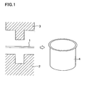
- a thin metal sheet 1 is placed between a female jig 2 and a punch 3 to fabricate a pipe 4 having a bottom. Deeper the pipe 4 is, more readily the pipe 4 can be spun. Hence, it is preferable that the pipe 4 is fabricated by warm drawing where the female jig 2 is heated and the punch 3 is cooled.
- a critical drawing ratio which is defined as a ratio of a diameter (A) of a cylindrical object to a diameter (B) of a punch (A/B)
- A/B a critical drawing ratio of a diameter of a cylindrical object to a diameter of a punch
- the metal sheet 1 In warm drawing, it is preferable for the metal sheet 1 to have a thickness in the range of 0.1 to 1.0 mm, and more preferable to have a thickness in the range of 0.3 to 0.5 mm.
- the pipe 4 is annealed such that the pipe 4 has a desired hardness.
- the pipe 4 is subject to spinning working by means of a spinning machine.
- the spinning machine is comprised of a pipe rotator 5 which rotates the pipe 4 around an axis thereof, a jig 6 having a top having an acute angle, a mover 7 movable both in a direction B perpendicular to the axis of the pipe 4 and in a direction A parallel to the axis of the pipe 4, a sensor 20 which measures a thickness of a wall 4a of the pipe 4 and transmits a signal 20a indicative of a measured thickness of a wall of the pipe 4, and a controller 30 which moves mover 7 in the direction B in accordance with the signal 20a transmitted from the sensor 20, to thereby reduce a thickness of a wall of the pipe 4, and controls a moving speed of the mover 7 in the direction A.
- the jig 6 is fixed to the mover 7, and hence, can move both in the directions A and B together with the mover 7.
- the pipe rotator 5 is inserted into the pipe 4 having a bottom 4b, and then, the pipe rotator 5 starts rotating the pipe 4 around an axis of the pipe 4.
- the controller 7 moves the mover 7 and the jig 6 in the direction B until the jig 6 makes contact with an outer surface of a wall 4a of the pipe 4. Then, the controller 7 further moves the mover 7 and hence the jig 6 in the direction B such that the jig 6 is compressed onto the outer wall 4a of the pipe 4 at a uniform pressure. Then, spinning working to the outer wall 4a of the pipe 4 starts.
- the jig 6 is fixed to the mover 7. By moving the jig 6 through the mover 7, it is possible to locate the jig 6 remote from an outer surface of the pipe rotator 5 by a certain distance. As mentioned later, a distance between the jig 6 and an outer surface of the pipe rotator 5 would be equal to a thickness of a later mentioned metal cylinder 8.
- the mover 7 moves the jig 6 far away from a bottom 4b of the pipe 4, that is, to a direction C with the jig 6 being pressed onto the outer wall 4a of the pipe 4.
- the outer wall 4a of the pipe 4 is drawn, and hence, lengthened and reduced in a thickness.
- the pipe 4 would have a thickness equal to a distance between a top of the jig 6 and an outer surface of the pipe rotator 5.
- the jig 6 is designed to have a conical top for drawing the outer wall 4a of the pipe 4.
- a roller made of a hard material may be used in place of the jig 6.
- the sensor 20 measures a thickness of the wall 4a of the pipe 4 in the direction A while the jig 6 draws the wall 4a of the pipe 4, and transmits a signal 20a indicative of the measured thickness of the wall 4a of the pipe 4, to the controller 30.
- the controller 30 On receipt of the signal 20a from the sensor 20, if the controller 30 judges a thickness of the wall 4a is thicker than a predetermined thickness, the controller 30 moves the mover 7 further towards the pipe 4, that is, varies a pressure exerted onto an outer surface of the wall 4a, and causes the jig 6 to draw the wall 4a until the wall 4a reaches a predetermined thickness.
- the sensor 20 in cooperation with the controller 30 makes it possible for the wall 4a of the pipe 4 to have a constant thickness.
- the controller 30 may move the jig 6 back to the certain portion, and causes the jig 6 to draw the certain portion until the certain portion has a predetermined thickness.
- the pipe 4 when the pipe 4 is fabricated to have the wall 4a having a thickness equal to or smaller than 0.09 mm, it would be possible to form the wall 4a having a desired thickness with tolerance being within ⁇ 2.5 micrometers.
- the senor 20 may be comprised of a supersonic pulse reflection type sensor which transmits supersonic pulses to an object, and receives supersonic pulses having been reflected at the object. Since supersonic pulses reflect at different materials at different reflection rates, it would be possible to measure a thickness of the wall 4a of the pipe 4, if the pipe 4 and the pipe rotator 5 are composed of different materials from each other.
- any sensor might be selected as the sensor 20 for sensing a thickness of the wall 4a of the pipe 4, unless it can measure a thickness of the wall 4a.
- the mover 7 is designed as a single device in the embodiment, the mover 7 may be designed to be comprised of a first device for moving the jig 6 in the direction B and a second device for moving the jig 6 in the direction A.
- the controller 30 further controls a speed at which the mover 7 moves in the direction A.
- the controller 30 may not only move the mover 7 further towards the pipe 4, but also move the mover 7 more slowly in the direction A, and causes the jig 6 to draw the wall 4a until the wall 4a reaches a predetermined thickness.
- the spinning machine may be of a horizontal type or a vertical type. From the standpoint of workability, it is preferable to select a horizontal type spinning machine.
- the pipe 4 is cut at its opposite ends by means of a cutter 27 such that the pipe 4 has a desired length and having a thickness smaller than 0.03 mm, as illustrated in FIG. 3.
- the pipe 4 is finished so as to have an outer diameter at an opening end with a tolerance equal to or smaller than 0.05%.
- a tolerance is equal to or smaller than 15 micrometers.
- the metal cylinder 8 is composed of SUS304
- the metal cylinder may be composed of materials other than SUS.
- the metal cylinder may be composed of stainless steel, rolled nickel, nickel alloy, titanium, titanium alloy, tantalum, molybdenum, hastelloy, permalloy, marageing steel, aluminum, aluminum alloy, copper, copper alloy, pure iron or steel.
- the wall 4a of the pipe 4 is drawn by the single jig 6.
- a plurality of jigs 6 may be used for drawing the pipe 4.
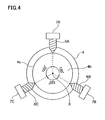
- FIG. 4 illustrates one example of arrangement of the jigs, in which three jigs 6A, 6B and 6C are arranged around a center of the pipe 4 in 120-degree circumference angles. Each of the jigs 6A, 6B and 6C is fixed to a mover 7A, 7B and 7C, respectively.
- the wall 4a of the pipe 4 By drawing the wall 4a of the pipe 4 by means of the three jigs 6A, 6B and 6C, it would be possible to prevent deviation of an axis X of the pipe rotator 5 while the pipe 4 is drawn, ensuring that the wall 4a is drawn with high accuracy. As a result, the wall 4a can be drawn to a thickness or smaller than 0.03 mm, for instance.
- jigs may be used for drawing the pipe 4, in which case, it is preferable that the jigs are arranged around the pipe 4 at a common circumference angle.
- FIGs. 5 to 7 illustrate an example of a use of the above-mentioned metal cylindrical film. As illustrated in FIGs. 5 to 7, the metal cylindrical film may be used as a part of a roller assembly.
- a metal cylindrical film 8A is wound around two rollers 9 and 11 arranged such that axes of the rollers 9 and 11 are parallel to each other.
- the metal cylindrical film 8A has the same width as a length of the rollers 9 and 11, and hence, entirely covers the rollers 9 and 11 therewith.
- the metal cylindrical film 8A is composed of SUS304, and has a thickness of 0.05 mm or 50 micrometers.
- each of the rollers 9 and 11 has a support shaft 12 and 13 projecting in an axis-wise direction thereof from opposite end surfaces of the rollers 9 and 11. As illustrated in FIG. 7, the rollers 9 and 11 are supported with sidewalls 14 at which the support shafts 12 and 13 are rotatably supported.
- the sidewall 14 is formed with a circular hole 15 having the same diameter as a diameter of the support shaft 12, and an elongate hole 16 having a height equal to a diameter of the support shaft 13 and a horizontal length longer than a diameter of the support shaft 13.
- the roller 9 is supported with the sidewall 14 by inserting the support shaft 12 into the circular hole 15.
- the roller 11 is fixed to the sidewall 14 by inserting the support shaft 13 into the elongate hole 16, and fixing the support shaft 13 at a desired location in the elongate hole 16 by means of a bolt and a nut, for instance.
- the metal cylindrical film 8A can be kept in tension by adjusting a location at which the roller 11 is fixed.
- the roller assembly as illustrated in FIGs. 5 to 7 may be used as a photosensitive drum, or a heater roll or a fixing roll in a printer.
- the roller 9 and 11 can have a smaller diameter than a diameter of a conventional photosensitive drum. Hence, it would be possible to fabricate a photosensitive drum having a smaller height than a height of a conventional photosensitive height. Thus, by incorporating the roller assembly including the metal cylindrical film 8A, into a printer, it would be possible to make a height of a printer significantly smaller.
- the roller assembly including the metal cylindrical film 8A has a planar portion 17 on the metal cylindrical film 8A in dependence on a distance between the rollers 9 and 11, as illustrated in FIG. 6.
- toner adhering to a paper can be thermally fixed onto the paper on the planar portion 17, which ensures a wider area for thermally fixating toner, than an area presented by a conventional heater roll.
- a developing unit may be arranged on the planar portion 17.
- the metal cylindrical film 8A since the metal cylindrical film 8A is thin, the metal cylindrical film 8A has a high thermal conductivity. That is, heat is likely to be transferred through the metal cylindrical film 8A. This ensures it possible to remarkably shorten a period of time necessary for heating a heater roll in comparison with a conventional heater roll. Accordingly, it is possible to shorten a period of time after a printer has been turned on until the printer becomes workable.
- FIG. 8 shows another use of a metal cylindrical film.
- a metal cylindrical film 8B may be used as a thermally fixing roll. As illustrated in FIG. 8, a pair of guides 18 is incorporated in the metal cylindrical film 8B.
- the guides 18 have an arcuate outer surface, and hence, can keep the metal cylindrical film 8B to be a cylinder.
- a heater 19 is sandwiched between the guides 18.
- the heater 19 is comprised of a halogen lamp or a ceramic heater, for instance.
- a nip roll 21 is located in facing relation to the metal cylindrical film 8B formed as a thermally fixing roll.
- a sheet 22 to which toner is adhered is fed towards the metal cylindrical film 8B and the nip roll 2i, and then, sandwiched between the metal cylindrical film 8B and the nip roll 21, and subsequently, heated by the heater 19. As a result, toner is thermally fixed to the sheet 22.
- the heater 19 can be arranged in the metal cylindrical film 8B, and hence, heat generated by the heater 19 can be transferred directly to the metal cylindrical film 8B. Thus, it would be possible to significantly enhance a heat transfer efficiency from the heater 19 to the metal cylindrical film 8B.
- the metal cylindrical film 8B is formed of a thin metal sheet, it is possible to rapidly heat the metal cylindrical film 8B up to a temperature necessary for fixing toner onto the sheet 22. Namely, it is possible to shorten a period of time after a printer has been turned on until the printer becomes workable.
Landscapes
- Engineering & Computer Science (AREA)
- Mechanical Engineering (AREA)
- Shaping Metal By Deep-Drawing, Or The Like (AREA)
- Rolls And Other Rotary Bodies (AREA)
- Fixing For Electrophotography (AREA)
- Discharging, Photosensitive Material Shape In Electrophotography (AREA)
- Photoreceptors In Electrophotography (AREA)
- Electrophotography Configuration And Component (AREA)
- Lining Or Joining Of Plastics Or The Like (AREA)
- A Measuring Device Byusing Mechanical Method (AREA)
Applications Claiming Priority (2)
| Application Number | Priority Date | Filing Date | Title |
|---|---|---|---|
| JP2002081679A JP3499233B2 (ja) | 2002-03-22 | 2002-03-22 | 金属円筒体及びその製造方法並びに製造装置 |
| JP2002081679 | 2002-03-22 |
Publications (3)
| Publication Number | Publication Date |
|---|---|
| EP1348498A2 true EP1348498A2 (de) | 2003-10-01 |
| EP1348498A3 EP1348498A3 (de) | 2003-12-17 |
| EP1348498B1 EP1348498B1 (de) | 2007-05-23 |
Family
ID=27800392
Family Applications (1)
| Application Number | Title | Priority Date | Filing Date |
|---|---|---|---|
| EP03006380A Expired - Lifetime EP1348498B1 (de) | 2002-03-22 | 2003-03-20 | Verfahren und Vorrichtung zur Herstellung einer lichtempfindlichen Trommel oder eines Fixierbands |
Country Status (5)
| Country | Link |
|---|---|
| US (2) | US20030177802A1 (de) |
| EP (1) | EP1348498B1 (de) |
| JP (1) | JP3499233B2 (de) |
| CN (2) | CN101318208A (de) |
| DE (1) | DE60313912T2 (de) |
Cited By (1)
| Publication number | Priority date | Publication date | Assignee | Title |
|---|---|---|---|---|
| US8997541B2 (en) | 2009-07-09 | 2015-04-07 | Leifeld Metal Spinning Ag | Method and device for stretch-flow forming |
Families Citing this family (17)
| Publication number | Priority date | Publication date | Assignee | Title |
|---|---|---|---|---|
| JP4911739B2 (ja) * | 2008-07-28 | 2012-04-04 | 株式会社ディムコ | 回転加工装置における金属円筒体加工方法 |
| CN101745577B (zh) * | 2008-12-17 | 2012-06-20 | 北京有色金属研究总院 | 一种碳钢内衬不锈钢复合管旋压加工方法 |
| CN101767139A (zh) * | 2010-03-04 | 2010-07-07 | 刘江 | 打印机、复印机用超薄圆筒不锈钢管膜的捋加工方法 |
| JP5352908B2 (ja) * | 2011-03-15 | 2013-11-27 | 住友電工ファインポリマー株式会社 | ローラへのガイドリング取付方法およびガイドリング取付用治具 |
| JP6308008B2 (ja) * | 2014-05-08 | 2018-04-11 | 富士ゼロックス株式会社 | 円筒体の製造方法、像保持体、画像形成装置 |
| EP3059024B1 (de) * | 2015-02-17 | 2023-07-19 | K.K. Endo Seisakusho | Fixierhülse und herstellungsverfahren dafür |
| CN105537449B (zh) * | 2016-01-26 | 2017-07-18 | 湖北三江航天江北机械工程有限公司 | 铝合金薄壁回转体旋压加工方法 |
| EP3398698B2 (de) * | 2017-05-05 | 2024-08-28 | Leifeld Metal Spinning GmbH | Verfahren und vorrichtung zum inkrementellen umformen eines metallischen werkstücks |
| CN109433897A (zh) * | 2018-12-06 | 2019-03-08 | 内蒙古航天红岗机械有限公司 | 一种圆筒收口的强力旋压方法 |
| GB201903228D0 (en) | 2019-03-11 | 2019-04-24 | Nicoventures Trading Ltd | Aerosol generation device heater element manufacture |
| CN110479922B (zh) * | 2019-08-02 | 2020-08-04 | 武汉理工大学 | 大型薄壁外t形环状构件约束轧制成形方法 |
| CN110976603A (zh) * | 2019-12-30 | 2020-04-10 | 西安航天动力机械有限公司 | 一种阴极辊用细晶钛筒的制备方法 |
| CN112058937A (zh) * | 2020-07-29 | 2020-12-11 | 宁波大学 | 一种长空心管内壁减薄成形方法 |
| CN112577387B (zh) * | 2020-12-29 | 2022-06-07 | 华侨大学 | 一种基于视觉千分尺的测量钢管内外壁及壁厚测量方法 |
| CN114406080B (zh) * | 2022-01-24 | 2024-05-31 | 中国航空制造技术研究院 | 一种带内筋薄壁构件的挤旋成形方法及成形工装 |
| CN114589467B (zh) * | 2022-03-29 | 2023-04-28 | 成都光明派特贵金属有限公司 | 贵金属多级变径通道及其制作方法 |
| KR102867689B1 (ko) | 2022-05-27 | 2025-10-15 | 주식회사 일광테크 | 후방 유동성형의 자동제어 시스템 |
Family Cites Families (37)
| Publication number | Priority date | Publication date | Assignee | Title |
|---|---|---|---|---|
| US1974441A (en) * | 1929-10-09 | 1934-09-25 | Celluloid Corp | Process and apparatus for electroplating |
| US3826124A (en) * | 1972-10-25 | 1974-07-30 | Zirconium Technology Corp | Manufacture of tubes with improved metallic yield strength and elongation properties |
| JPS5346472A (en) | 1976-10-08 | 1978-04-26 | Tokyo Shibaura Electric Co | Method of fabricating extremely thin cylindrical parts |
| JPS53133570A (en) * | 1977-04-28 | 1978-11-21 | Kyodo Printing Co Ltd | Manufacturing method of compound tube |
| US4173876A (en) * | 1978-03-27 | 1979-11-13 | Nudyne Corporation | Method of producing metal tubing |
| US4357618A (en) * | 1978-10-16 | 1982-11-02 | Algographic Associates | Electrostatic imaging apparatus |
| JPS5756118A (en) * | 1980-09-19 | 1982-04-03 | Mitsubishi Heavy Ind Ltd | Forming method for tubular workpiece |
| JPS5785618A (en) * | 1980-11-14 | 1982-05-28 | Mitsubishi Heavy Ind Ltd | Forming method for cylindrical workpiece |
| JPS5835025A (ja) | 1981-08-25 | 1983-03-01 | Toshiba Corp | スピニング成形方法 |
| JPS5884619A (ja) | 1981-11-12 | 1983-05-20 | Toshiba Corp | スピニング成形方法 |
| JPS58107224A (ja) | 1981-12-21 | 1983-06-25 | Toshiba Corp | 薄肉ノズルのスピニング加工方法 |
| JPS58107223A (ja) | 1981-12-21 | 1983-06-25 | Toshiba Corp | スピニング加工方法 |
| JPS61107008A (ja) | 1984-10-30 | 1986-05-24 | Matsushita Electric Ind Co Ltd | 燃焼筒 |
| JPS6434527A (en) | 1987-04-21 | 1989-02-06 | Asahi Chemical Ind | Aluminum alloy tube having smooth uneven pattern |
| JPH01130822A (ja) | 1987-11-16 | 1989-05-23 | Asahi Chem Ind Co Ltd | 金属管の表面加工方法 |
| JP2708468B2 (ja) * | 1988-03-14 | 1998-02-04 | 株式会社リコー | 電子写真感光体 |
| US5035197A (en) * | 1988-07-14 | 1991-07-30 | Minolta Camera Kabushiki Kaisha | Developing device |
| DD300696A7 (de) | 1989-06-12 | 1992-07-09 | Rohrkombinat Stahl & Walzwerk | Verfahren zur ueberwachung von rohrstossbankanlagen |
| JP2627231B2 (ja) * | 1990-11-16 | 1997-07-02 | 株式会社リコー | 電子写真感光体用基体及びその製造方法 |
| US5128091A (en) * | 1991-02-25 | 1992-07-07 | Xerox Corporation | Processes for forming polymeric seamless belts and imaging members |
| US5121139A (en) * | 1991-04-29 | 1992-06-09 | Tektronix, Inc. | Compact ink jet printer having a drum drive mechanism |
| US5324248A (en) * | 1992-11-03 | 1994-06-28 | Composite Development Corporation | Composite machine roll and method of manufacture |
| GB9319408D0 (en) * | 1993-09-20 | 1993-11-03 | Avondale Property Holdings Ltd | Extrusion of laminate pipes |
| JP2734980B2 (ja) | 1994-04-19 | 1998-04-02 | タイガー魔法瓶株式会社 | 金属製二重容器の製造方法およびその方法により製造された金属製二重容器 |
| JP3787900B2 (ja) | 1995-07-20 | 2006-06-21 | 株式会社日立製作所 | 金属板の逐次張出し成形装置 |
| US5669578A (en) * | 1995-09-22 | 1997-09-23 | Ncr Corporation | Crush-proof extrusion core |
| JP2841356B2 (ja) | 1995-11-29 | 1998-12-24 | 北栄精機株式会社 | 電気ポット |
| JP3712086B2 (ja) | 1996-06-20 | 2005-11-02 | 住友電気工業株式会社 | 定着用ベルト及び定着装置 |
| US5695847A (en) * | 1996-07-10 | 1997-12-09 | Browne; James M. | Thermally conductive joining film |
| JPH10140387A (ja) | 1996-11-11 | 1998-05-26 | Naikai Aakit:Kk | 金属箔電着ドラム |
| EP0957404B1 (de) * | 1998-05-14 | 2006-01-11 | Canon Kabushiki Kaisha | Elektrophotographischer Bildherstellungsapparat |
| JP3406293B2 (ja) | 1999-12-03 | 2003-05-12 | 株式会社ディムコ | 金属環状体並びにその製造方法 |
| JP2001330081A (ja) | 2000-05-23 | 2001-11-30 | Dymco:Kk | 金属製無端ベルト及びその製造方法 |
| JP4015800B2 (ja) * | 2000-06-30 | 2007-11-28 | 株式会社東芝 | 湿式画像形成装置 |
| JP2002169392A (ja) | 2000-11-30 | 2002-06-14 | Shin Etsu Polymer Co Ltd | 画像形成装置のシームレスベルト基材及びこれを用いた定着ベルト、感光体ベルト |
| US6564033B2 (en) | 2000-12-12 | 2003-05-13 | Canon Kabushiki Kaisha | Fixing belt and image heating and fixing apparatus |
| US6716148B1 (en) * | 2001-07-17 | 2004-04-06 | Double E Co., Inc. | Metal-sleeved carbon fiber anilox roller base |
-
2002
- 2002-03-22 JP JP2002081679A patent/JP3499233B2/ja not_active Expired - Fee Related
-
2003
- 2003-03-19 US US10/391,862 patent/US20030177802A1/en not_active Abandoned
- 2003-03-20 EP EP03006380A patent/EP1348498B1/de not_active Expired - Lifetime
- 2003-03-20 DE DE60313912T patent/DE60313912T2/de not_active Expired - Lifetime
- 2003-03-21 CN CNA2008101361497A patent/CN101318208A/zh active Pending
- 2003-03-21 CN CN03107281A patent/CN1446646A/zh active Pending
-
2007
- 2007-04-23 US US11/739,025 patent/US7963016B2/en not_active Expired - Fee Related
Cited By (1)
| Publication number | Priority date | Publication date | Assignee | Title |
|---|---|---|---|---|
| US8997541B2 (en) | 2009-07-09 | 2015-04-07 | Leifeld Metal Spinning Ag | Method and device for stretch-flow forming |
Also Published As
| Publication number | Publication date |
|---|---|
| US20070186402A1 (en) | 2007-08-16 |
| CN101318208A (zh) | 2008-12-10 |
| DE60313912T2 (de) | 2008-01-17 |
| CN1446646A (zh) | 2003-10-08 |
| JP3499233B2 (ja) | 2004-02-23 |
| US7963016B2 (en) | 2011-06-21 |
| EP1348498A3 (de) | 2003-12-17 |
| JP2003275834A (ja) | 2003-09-30 |
| DE60313912D1 (de) | 2007-07-05 |
| EP1348498B1 (de) | 2007-05-23 |
| US20030177802A1 (en) | 2003-09-25 |
Similar Documents
| Publication | Publication Date | Title |
|---|---|---|
| US7963016B2 (en) | Circular-shaped metal structure, method of fabricating the same, and apparatus for fabricating the same | |
| US6561001B2 (en) | Circular-shaped metal structure, method of fabricating the same, and apparatus for fabricating the same | |
| RU2561334C2 (ru) | Устройство нагрева изображений | |
| EP1424147B1 (de) | Kreisförmiger Metallgegenstand und Verfahren zu dessen Herstellung | |
| CN104281034A (zh) | 用于定影的辊、该辊的制造方法和定影装置 | |
| JP2001330081A (ja) | 金属製無端ベルト及びその製造方法 | |
| JP2004037555A (ja) | 外部加熱装置及びこれを用いた定着装置 | |
| JP3318039B2 (ja) | 定着装置 | |
| US20260104665A1 (en) | Fixing apparatus, and manufacturing method | |
| JP2006053494A (ja) | 定着装置、及びこれを使用した画像形成装置 | |
| JP2004163768A (ja) | 定着装置 | |
| JP3513306B2 (ja) | 定着装置 | |
| JP2001124148A (ja) | ベルト組立体の検査方法及び検査装置 | |
| JPH0728347A (ja) | 画像形成装置 | |
| JPH0934296A (ja) | 定着装置 | |
| JP2026068670A (ja) | 定着装置 | |
| JP6423771B2 (ja) | ステンレス鋼を使用した定着装置 | |
| JPH06250538A (ja) | 定着装置 | |
| JP2003295673A (ja) | 定着装置 | |
| JP2002106547A (ja) | 芯金構造体及び画像形成装置 | |
| JP2020134814A (ja) | 定着装置 | |
| JP2004020768A (ja) | 加圧装置、定着装置および画像形成装置 | |
| JP2002211782A (ja) | 搬送ローラ | |
| JPH08220909A (ja) | 画像形成装置 | |
| JPH0643550A (ja) | 平床式マイクロカメラ |
Legal Events
| Date | Code | Title | Description |
|---|---|---|---|
| PUAI | Public reference made under article 153(3) epc to a published international application that has entered the european phase |
Free format text: ORIGINAL CODE: 0009012 |
|
| AK | Designated contracting states |
Kind code of ref document: A2 Designated state(s): AT BE BG CH CY CZ DE DK EE ES FI FR GB GR HU IE IT LI LU MC NL PT SE SI SK TR |
|
| AX | Request for extension of the european patent |
Extension state: AL LT LV MK RO |
|
| PUAL | Search report despatched |
Free format text: ORIGINAL CODE: 0009013 |
|
| AK | Designated contracting states |
Kind code of ref document: A3 Designated state(s): AT BE BG CH CY CZ DE DK EE ES FI FR GB GR HU IE IT LI LU MC NL PT SE SI SK TR |
|
| AX | Request for extension of the european patent |
Extension state: AL LT LV MK RO |
|
| 17P | Request for examination filed |
Effective date: 20040505 |
|
| AKX | Designation fees paid |
Designated state(s): DE FR GB |
|
| RTI1 | Title (correction) |
Free format text: METHOD AND APPARATUS OF FABRICATING A PHOTOSENSITIVE DRUM OR FIXING BELT |
|
| GRAP | Despatch of communication of intention to grant a patent |
Free format text: ORIGINAL CODE: EPIDOSNIGR1 |
|
| GRAS | Grant fee paid |
Free format text: ORIGINAL CODE: EPIDOSNIGR3 |
|
| GRAA | (expected) grant |
Free format text: ORIGINAL CODE: 0009210 |
|
| AK | Designated contracting states |
Kind code of ref document: B1 Designated state(s): DE FR GB |
|
| REG | Reference to a national code |
Ref country code: GB Ref legal event code: FG4D |
|
| REF | Corresponds to: |
Ref document number: 60313912 Country of ref document: DE Date of ref document: 20070705 Kind code of ref document: P |
|
| ET | Fr: translation filed | ||
| PLBE | No opposition filed within time limit |
Free format text: ORIGINAL CODE: 0009261 |
|
| STAA | Information on the status of an ep patent application or granted ep patent |
Free format text: STATUS: NO OPPOSITION FILED WITHIN TIME LIMIT |
|
| 26N | No opposition filed |
Effective date: 20080226 |
|
| REG | Reference to a national code |
Ref country code: FR Ref legal event code: PLFP Year of fee payment: 14 |
|
| REG | Reference to a national code |
Ref country code: FR Ref legal event code: PLFP Year of fee payment: 15 |
|
| REG | Reference to a national code |
Ref country code: FR Ref legal event code: PLFP Year of fee payment: 16 |
|
| PGFP | Annual fee paid to national office [announced via postgrant information from national office to epo] |
Ref country code: GB Payment date: 20220321 Year of fee payment: 20 Ref country code: DE Payment date: 20220322 Year of fee payment: 20 |
|
| PGFP | Annual fee paid to national office [announced via postgrant information from national office to epo] |
Ref country code: FR Payment date: 20220322 Year of fee payment: 20 |
|
| REG | Reference to a national code |
Ref country code: DE Ref legal event code: R071 Ref document number: 60313912 Country of ref document: DE |
|
| REG | Reference to a national code |
Ref country code: GB Ref legal event code: PE20 Expiry date: 20230319 |
|
| PG25 | Lapsed in a contracting state [announced via postgrant information from national office to epo] |
Ref country code: GB Free format text: LAPSE BECAUSE OF EXPIRATION OF PROTECTION Effective date: 20230319 |