EP1348593B1 - Armlehne mit beweglicher Armauflage, insbesondere für Fahrzeuge - Google Patents
Armlehne mit beweglicher Armauflage, insbesondere für Fahrzeuge Download PDFInfo
- Publication number
- EP1348593B1 EP1348593B1 EP03006963A EP03006963A EP1348593B1 EP 1348593 B1 EP1348593 B1 EP 1348593B1 EP 03006963 A EP03006963 A EP 03006963A EP 03006963 A EP03006963 A EP 03006963A EP 1348593 B1 EP1348593 B1 EP 1348593B1
- Authority
- EP
- European Patent Office
- Prior art keywords
- armrest
- support
- arm support
- guide rods
- arm
- Prior art date
- Legal status (The legal status is an assumption and is not a legal conclusion. Google has not performed a legal analysis and makes no representation as to the accuracy of the status listed.)
- Expired - Lifetime
Links
- 239000002184 metal Substances 0.000 claims abstract description 20
- 230000000717 retained effect Effects 0.000 claims 1
- 238000006073 displacement reaction Methods 0.000 description 4
- 238000004519 manufacturing process Methods 0.000 description 4
- 230000006835 compression Effects 0.000 description 3
- 238000007906 compression Methods 0.000 description 3
- 238000009434 installation Methods 0.000 description 3
- 229910000831 Steel Inorganic materials 0.000 description 1
- 230000002411 adverse Effects 0.000 description 1
- 230000015572 biosynthetic process Effects 0.000 description 1
- 150000001875 compounds Chemical class 0.000 description 1
- 238000010276 construction Methods 0.000 description 1
- 238000005058 metal casting Methods 0.000 description 1
- 239000006223 plastic coating Substances 0.000 description 1
- 238000004080 punching Methods 0.000 description 1
- 239000010959 steel Substances 0.000 description 1
- 239000013585 weight reducing agent Substances 0.000 description 1
Images

Classifications
-
- B—PERFORMING OPERATIONS; TRANSPORTING
- B60—VEHICLES IN GENERAL
- B60N—SEATS SPECIALLY ADAPTED FOR VEHICLES; VEHICLE PASSENGER ACCOMMODATION NOT OTHERWISE PROVIDED FOR
- B60N2/00—Seats specially adapted for vehicles; Arrangement or mounting of seats in vehicles
- B60N2/75—Arm-rests
- B60N2/753—Arm-rests movable to an inoperative position
-
- B—PERFORMING OPERATIONS; TRANSPORTING
- B60—VEHICLES IN GENERAL
- B60N—SEATS SPECIALLY ADAPTED FOR VEHICLES; VEHICLE PASSENGER ACCOMMODATION NOT OTHERWISE PROVIDED FOR
- B60N2/00—Seats specially adapted for vehicles; Arrangement or mounting of seats in vehicles
- B60N2/75—Arm-rests
- B60N2/763—Arm-rests adjustable
- B60N2/773—Longitudinal adjustment
Definitions
- the invention relates to an armrest with a longitudinally movable armrest, which can be used in particular between the front seats in the region of the center console of passenger cars.
- an armrest for a seat which is provided on a base device which is pivotable about a seat-fixed pivot axis.
- the base device has a linear guide, which consist of a pair of guide rods, which are arranged parallel to each other, and two bushings, which form the bearing point of the armrest.
- the guide rods are guided with sliding tolerance in the bearing point.
- an armrest with a longitudinally adjustable Armauflageelement This covers a carriage which is slidably mounted on a base body of the armrest.
- the Armauflageelement is formed bendable at least in a partial area, so that when moving the carriage forward or backward, the Armauflageelement can extend accordingly.
- the unneeded length of the armrest element invisibly moves under the carriage.
- U1 is an armrest, consisting of a support element and an armrest, known, wherein the linear guide of the armrest, a pair of parallel spaced guide rods and each an associated guide are arranged.
- the guide rods are arranged linearly movable in guides and firmly connected to the support element.
- the guide rods are connected to an adjusting and braking device, through which the guide rods are displaceable in the longitudinal direction in the unloaded state of the armrest and can be locked in the loading position of the armrest in the respective position.
- the guides for the guide rods are arranged on a respective lever.
- the levers are rotatably received in separate bearing blocks of a common base plate and pressed independently by springs against a stop.
- the invention has for its object to provide an armrest with movable armrest, especially for vehicles, which is characterized by a simplified adjustment mechanism for the linear movement and a low production cost and in which the technical components are not visible in the extended or folded state of the armrest ,
- the armrest is designed as an elongate hollow body with a flat bottom or lower part.
- the armrest has at one end an opening for receiving the base support and is pushed during assembly on this. After installation of the base support and armrest, the armrest encloses the base support almost completely, except for the arms of the armrest holder. Due to the cup-shaped design of the base support the functionally related components for the realization of the sliding movement are completely covered and are no longer visually visible.
- On the underside of the armrest are arranged in the front and rear area inwardly directed bearings for receiving the guide rods.
- the basic carrier is equipped with linear guides for the guide rods, which are integrally formed on the basic carrier or are part of the basic carrier.
- at least one spring-loaded detent element and a spring-loaded brake element are arranged on the base carrier.
- These are preferably equipped with spherical elements which constantly press against the underside of the armrest, wherein the locking element is locked in different displacement positions with the armrest.
- the armrest is provided for this purpose on the underside with longitudinal sliding surfaces.
- the corresponding with the locking element sliding surface has a plurality of spaced-apart depressions, in which engages the detent ball of the Ratiatas and thereby locks the armrest in the desired position.
- the armrest stands out by a simple structural design and can be produced inexpensively. An advantage is also that due to the structural design, the armrest in a relatively large range, of up to about 120 mm, is adjustable.
- the base support which is formed with the armrest support arm support arms, may be preferably formed as a hybrid component consisting of a metal support member overmolded with plastic.
- This design of the base support leads compared to the otherwise conventional construction as a metal casting to a significant weight reduction of this component.
- the plastic coating allows an attractive color and shape for this when extending the armrest from above visible component.
- the metal carrier part can be made of a thin-walled sheet, which is at least partially perforated.
- the required linear guides for the guide rods and the armrest bracket can be formed on the sheet metal part with. This can be made by punching and drawing. Due to the load on the armrest, the arms for the armrest bracket should be made of metal.
- the linear guides for the guide rods can be made of plastic and molded with. Another possibility is to make the arms for the holder made of metal and make the base plate with the linear guides made of plastic and to inject them to the armrest holder.
- the sleeve-shaped components of locking and braking element can either be formed as an insert on the base plate or screwed into a molded threaded part.
- the hollow body-shaped armrest is preferably made of plastic and can be designed as a one-piece or two-piece component.
- the two split halves in the longitudinal direction can then be joined together in a conventional manner.
- the required bearings for the guide rods are formed on the inside of the armrest.
- the armrest consists of an armrest 1 and a base support 2, which is connected to the armrest holder, consisting of the two support arms 3, 4.
- the armrest can be installed, for example, between the front seats of a passenger car, in the area of the center console 5, pivotally, as in Fig. 2 shown.
- the support arms 3, 4 are mounted pivotably on a shaft 6.
- the design of the armrest holder depends on the existing possibilities at the installation of the armrest.
- the armrest 1 is formed as an elongated hollow body having a flat bottom or lower part 1a and a slightly curved top 1b and a pointing in the direction of the armrest holder 3, 4 opening 1c.
- the hollow body may be either one-piece or two-piece, divided in the longitudinal direction, executed.
- Lower part 1a and upper part 1b can then z. B. connected by a clip or snap connection or in any other suitable manner.
- the armrest 1 consists of a plastic component, which is subsequently provided on its upper side with a cover.
- the armrest 1 On the underside 1a of the armrest 1 are located in the front and rear areas each have two inwardly facing bearings 7 and 8 for receiving the guide rods 9, 10.
- the bearings 7 and 8 are integrally formed on the armrest 1 and form a component with this.
- the two symmetrically arranged, parallel spaced guide rods 9, 10 are fixed in the pointing in the extension direction bearings 7 on the armrest 1 and guided in located on the base support 2 linear guides 2a and 2b.
- the armrest can be displaced in the intended adjustment range, preferably 80 to 90 mm, in the longitudinal direction.
- a locking element 12 and a brake member 11 are fixed, which consist of a sleeve-shaped member 15 with an integrated compression spring and a steel or plastic ball.
- Locking element 12 and brake element 11 are equipped with compression springs of different voltage and arranged in parallel spaced in the transverse direction.
- On the inside of the lower part 1a of the armrest 1 there are a sliding surface 14 corresponding to the locking element 12 and a sliding surface 13 corresponding to the brake element 11. Both sliding surfaces 13, 14 extend in the longitudinal direction. In the sliding surface 14 four arranged at defined intervals depressions 14 a are introduced, which allow a locking with the detent ball of the locking element 12 in the respective displacement positions of the armrest 1.
- the balls of the locking-12 and the brake element 11 constantly press against the sliding surfaces 14 and 13 of the armrest 1 and prevent unwanted movement of the armrest.
- the operator can shift them into the desired latching position by a manual displacement movement of the armrest 1.
- the shell-shaped base support 2 is preferably formed as a hybrid component and consists of a metal support member 2c, which is encapsulated on all sides with plastic, as in the FIGS. 3 and 4 shown. In the embodiment shown, only the actual base support 2 is covered with a plastic layer 2d.
- the likewise consisting of metal retaining arms 3, 4 and the linear guides 2a and 2b are not molded.
- the linear guides 2a, 2b are pressed out of the metal part, preferably a sheet, and provided with guide sleeves. Of course, the linear guides 2a, 2b may be formed of plastic.
- the hybrid component can be injection-molded with plastic with simultaneous formation of the linear guides 2a, 2b.
- the latching elements 11, 12 can either also be encapsulated as a so-called insert with or screwed, as in Fig. 1 shown.
- the design of the base support as a hybrid component has the advantage that a significant weight saving can be achieved without adversely affecting the required stability and strength.
- the metal carrier part which is preferably made of sheet metal, can additionally be punched in order to improve the metal / plastic compound.
- the combination of metal component / plastic for the production of the base support allows an attractive design in color and design. Due to the cup-shaped design of the base support the functionally related components for the realization of the sliding movement are completely covered and are not visible during the sliding movement of the armrest.
Landscapes
- Engineering & Computer Science (AREA)
- Aviation & Aerospace Engineering (AREA)
- Transportation (AREA)
- Mechanical Engineering (AREA)
- Seats For Vehicles (AREA)
- Passenger Equipment (AREA)
- Vehicle Step Arrangements And Article Storage (AREA)
Description
- Die Erfindung betrifft eine Armlehne mit in Längsrichtung beweglicher Armauflage, die insbesondere zwischen den Vordersitzen im Bereich der Mittelkonsole von Personenkraftwagen einsetzbar ist.
- Aus der gattungsbildenden
DE 199 15 469 A1 ist eine Armlehne für einen Sitz bekannt, die an einer Basiseinrichtung vorgesehen ist, die um eine sitzfeste Schwenkachse verschwenkbar ist. Zur Verstellung der Armlehne in Längsrichtung weist die Basiseinrichtung eine Linearführung auf, die aus einem Paar Führungsstangen, die parallel beanstandet zueinander angeordnet sind, und zwei Buchsen, die die Lagerstelle der Armlehne bilden, bestehen. Die Führungsstangen sind mit Gleitsitztoleranz in der Lagerstelle geführt. Der Nachteil dieser Lösung besteht darin, dass die Armlehne frei hin- und herbewegbar ist und nicht in einer für den Fahrer bevorzugten Stellung arretierbar ist. Der Fahrer bzw. Bediener muss die Armlehne verstellen. Bei Bremsmanövern kann es vorkommen, dass sich die Armlehne von selbst verstellt, wodurch die Aufmerksamkeit des Fahrers im Straßenverkehr beeinträchtigt wird. - In der
DE 198 46 030 C1 ist eine Armlehne mit einem längsverstellbaren Armauflageelement beschrieben. Dieses überdeckt einen Schlitten, der verschiebbar an einem Grundkörper der Armlehne gelagert ist. Das Armauflageelement ist zumindest in einem Teilbereich biegbar ausgebildet, so dass beim Verschieben des Schlittens nach vorn oder nach hinten sich das Armauflageelement entsprechend verlängern kann. Je nach eingestellter Schlittenlänge wandert die nicht benötigte Länge des Armauflageelementes unsichtbar unter den Schlitten. - Diese Lösung ist in ihrer Herstellung sehr aufwendig und kostenintensiv. Außerdem muss der Fahrer bzw. Bediener die Verstellung des Schlittens selbst vornehmen.
- Aus der
DE 201 00 902 U1 ist eine Armlehne, bestehend aus einem Auflageelement und einer Armauflage, bekannt, wobei zur Linearführung der Armauflage ein Paar parallel beabstandeter Führungsstangen und jeweils eine dazugehörige Führung angeordnet sind. Die Führungsstangen sind in Führungen linearbeweglich angeordnet und mit dem Auflageelement fest verbunden. Die Führungsstangen sind mit einer Einstell- und Bremsvorrichtung verbunden, durch die im Entlastungszustand der Armauflage die Führungsstangen in Längsrichtung verschiebbar sind und im Belastungszustand der Armauflage in der jeweiligen Stellung arretiert werden können. - Die Führungen für die Führungsstangen sind an jeweils einem Hebel angeordnet. Die Hebel sind in getrennten Lagerböcken einer gemeinsamen Grundplatte drehbar aufgenommen und mittels Federn unabhängig voneinander gegen einen Anschlag gedrückt.
- Aufgrund der vorgesehenen Möglichkeit der Verschiebebewegung und Arretierung der Armauflage in Abhängigkeit vom Be- bzw. Entlastungszustand ist diese Lösung in ihrer Herstellung und Montage relativ aufwendig.
- Der Erfindung liegt die Aufgabe zugrunde, eine Armlehne mit beweglicher Armauflage, insbesondere für Fahrzeuge, zu schaffen, die sich durch einen vereinfachten Verstellmechanismus für die Linearbewegung und einen geringen Herstellungsaufwand auszeichnet und bei der die technischen Bauteile im ausgefahrenen oder hochgeklappten Zustand der Armlehne nicht sichtbar sind.
- Erfindungsgemäß wird die Aufgabe durch die im Anspruch 1 angegebenen Merkmale gelöst. Geeignete Ausgestaltungsvarianten sind Gegenstand der Ansprüche 2 bis 10. Die Armauflage ist als länglicher Hohlkörper mit einer ebenen Unterseite bzw. Unterteil ausgebildet. Die Armauflage besitzt an einem Ende eine Öffnung zur Aufnahme des Grundträgers und wird während der Montage auf diesen aufgeschoben. Nach erfolgter Montage von Grundträger und Armauflage umschließt die Armauflage den Grundträger nahezu vollständig, bis auf die Haltearme der Armlehnenhalterung. Durch die schalenförmige Ausbildung des Grundträgers werden die funktionsbedingten Bauteile für die Realisierung der Verschiebebewegung vollständig abgedeckt und sind optisch nicht mehr sichtbar. An der Unterseite der Armauflage sind im vorderen und hinteren Bereich nach innen gerichtete Lagerstellen zur Aufnahme der Führungsstangen angeordnet. Der Grundträger ist mit Linearführungen für die Führungsstangen ausgerüstet, die an dem Grundträger angeformt bzw. Bestandteil des Grundträgers sind. Zur Einstellung der von dem Bediener gewünschten Lage der Armauflage sind an dem Grundträger mindestens ein federbelastetes Rastelement und ein federbelastetes Bremselement angeordnet. Diese sind vorzugsweise mit kugelförmigen Elementen ausgerüstet, die ständig gegen die Unterseite der Armauflage drücken, wobei das Rastelement in verschiedenen Verschiebestellungen mit der Armauflage verrastet. Die Armauflage ist hierzu an der Unterseite mit in Längsrichtung verlaufenden Gleitflächen versehen. Die mit dem Rastelement korrespondierende Gleitfläche besitzt mehrere in definierten Abständen angeordnete Einsenkungen, in die die Rastkugel des Ratelementes eingreift und dadurch die Armauflage in der gewünschten Stellung arretiert. Da Rast- und Bremselement ständig gegen die Armauflage drücken, wird ein ungewolltes Verschieben der Armauflage ausgeschlossen. Die Armlehne zeichnet sich durch einen einfachen konstruktiven Aufbau aus und lässt sich kostengünstig herstellen. Ein Vorteil ist auch, dass aufgrund der konstruktiven Auslegung die Armauflage in einem relativ großen Bereich, von bis zu ca. 120 mm, verstellbar ist.
- Der Grundträger, der mit den Haltearmen für die Armlehnenhalterung ausgebildet ist, kann vorzugsweise als Hybridbauteil ausgebildet werden, das aus einem Metallträgerteil besteht, das mit Kunststoff umspritzt ist. Diese Bauweise des Grundträgers führt im Vergleich zu der ansonsten üblichen Bauweise als Metallgussteil zu einer wesentlichen Gewichtsreduzierung dieses Bauteils. Außerdem ermöglicht die Kunststoffummantelung eine ansprechende Farb- und Formgebung für dieses beim Ausfahren der Armauflage von oben sichtbare Bauteil.
- Außerdem ergeben sich verschiedene Möglichkeiten für eine kostengünstige Ausbildung des Grundträgers. So z. B. kann das Metallträgerteil aus einem dünnwandigen Blech gefertigt werden, das zumindest teilweise gelocht ist. Die erforderlichen Linearführungen für die Führungsstangen und die Armlehnenhalterung können an dem Blechbauteil mit angeformt werden. Dieses kann durch Stanzen und Ziehen hergestellt werden. Aufgrund der Belastung der Armlehne sollten die Arme für die Armlehnenhalterung aus Metall bestehen. Dagegen können die Linearführungen für die Führungsstangen aus Kunststoff bestehen und mit angespritzt werden. Eine andere Möglichkeit besteht auch darin, die Arme für die Halterung aus Metall zu fertigen und die Grundplatte mit den Linearführungen aus Kunststoff herzustellen und diese an der Armlehnenhalterung anzuspritzen.
- Die hülsenförmigen Bauteile von Rast- und Bremselement können entweder als Einlegeteil an der Grundplatte mit angeformt werden oder in ein angespritztes Gewindeteil eingeschraubt werden.
- Die hohlkörperförmige Armauflage wird vorzugsweise aus Kunststoff hergestellt und kann als einteiliges oder zweiteiliges Bauteil ausgeführt sein. Die beiden in Längsrichtung geteilten Hälften können dann in an sich bekannter Weise zusammengefügt werden. Die erforderlichen Lagerstellen für die Führungsstangen sind an der Innenseite der Armauflage angeformt.
- Die Erfindung soll nachstehend an einem Ausführungsbeispiel erläutert werden. In der zugehörigen Zeichnung zeigen
- Fig. 1
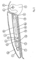
- die Armlehne in teilweise geschnittener perspektivischer Darstellung,
- Fig. 2
- die Armlehne gemäß
Fig. 1 als Längsschnitt in Einbaulage, - Fig. 3
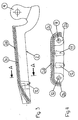
- den Grundträger der Armlehne als Längsschnitt und
- Fig. 4
- einen Schnitt gemäß der Linie A-A in
Fig. 3 . - Die Armlehne besteht aus einer Armauflage 1 und einem Grundträger 2, der mit der Armlehnenhalterung, bestehend aus den beiden Haltearmen 3, 4, verbunden ist. Die Armlehne kann z.B. zwischen den Vordersitzen eines Personenkraftwagens, im Bereich der Mittelkonsole 5, schwenkbar installiert werden, wie in
Fig. 2 gezeigt. Die Haltearme 3, 4 sind dabei auf einer Welle 6 schwenkbar gelagert. Die Ausbildung der Armlehnenhalterung richtet sich nach den vorhandenen Möglichkeiten am Einbauort der Armlehne. Wie insbesondere ausFig. 2 hervorgeht, ist die Armauflage 1 als länglicher Hohlkörper ausgebildet, der eine ebene Unterseite bzw. Unterteil 1a und ein leicht gewölbtes Oberteil 1b besitzt sowie eine in Richtung der Armlehnenhalterung 3, 4 zeigende Öffnung 1c. Der Hohlkörper kann entweder einteilig oder zweiteilig, in Längsrichtung geteilt, ausgeführt sein. Unterteil 1a und Oberteil 1b können dann z. B. durch eine Klips- oder Schnappverbindung oder auf sonstige geeignete Art und Weise miteinander verbunden werden. Die Armauflage 1 besteht aus einem Kunststoffbauteil, das nachträglich auf seiner Oberseite mit einem Bezug versehen wird. - An der Unterseite 1a der Armauflage 1 befinden sich im vorderen und hinteren Bereich jeweils zwei nach innen zeigende Lagerstellen 7 und 8 zur Aufnahme der Führungsstangen 9, 10. Die Lagerstellen 7 und 8 sind an der Armauflage 1 angeformt und bilden mit dieser ein Bauteil. Die beiden symmetrisch angeordneten, parallel beabstandeten Führungsstangen 9, 10 sind in den in Auszugsrichtung zeigenden Lagerstellen 7 an der Armauflage 1 befestigt und in an dem Grundträger 2 befindlichen Linearführungen 2a und 2b geführt. Dadurch kann die Armauflage in dem vorgesehenen Einstellbereich, vorzugsweise 80 bis 90 mm, in Längsrichtung verschoben werden. An der Innenseite des Grundträgers 2, der eine schalenförmige Kontur besitzt, sind ein Rastelement 12 und ein Bremselement 11 befestigt, die aus einem hülsenförmigen Bauteil 15 mit einer integrierten Druckfeder und einer Stahl- oder Kunststoffkugel bestehen. Rastelement 12 und Bremselement 11 sind mit Druckfedern unterschiedlicher Spannung ausgerüstet und in Querrichtung parallel beabstandet angeordnet. An der Innenseite des Unterteils 1a der Armauflage 1 befinden sich eine mit dem Rastelement 12 korrespondierende Gleitfläche 14 und eine mit dem Bremselement 11 korrespondierende Gleitfläche 13. Beide Gleitflächen 13, 14 verlaufen in Längsrichtung. In die Gleitfläche 14 sind vier in definierten Abständen angeordnete Einsenkungen 14a eingebracht, die eine Verrastung mit der Rastkugel des Rastelementes 12 in den jeweiligen Verschiebestellungen der Armauflage 1 ermöglichen.
- Die Kugeln des Rast-12 und des Bremselementes 11 drücken ständig gegen die Gleitflächen 14 und 13 der Armauflage 1 und verhindern eine ungewollte Bewegung der Armauflage. Der Bediener kann durch eine manuelle Verschiebebewegung der Armauflage 1, durch Überwindung der Vorspannung der Druckfedern in den Rast- und Bremselementen 12, 11, diese in die gewünschte verrastende Stellung verschieben.
- Während der Verschiebebewegung werden die in den Linearführungen 2a, 2b geführten Führungsstangen 9, 10 mit bewegt.
- Der schalenförmige Grundträger 2 ist vorzugsweise als Hybridbauteil ausgebildet und besteht aus einem Metallträgerteil 2c, das allseitig mit Kunststoff umspritzt ist, wie in den
Figuren 3 und 4 gezeigt. Bei der gezeigten Ausführungsvariante ist nur der eigentliche Grundträger 2 mit einer Kunststoffschicht 2d ummantelt. Die ebenfalls aus Metall bestehenden Haltearme 3, 4 und die Linearführungen 2a und 2b sind nicht umspritzt. Die Linearführungen 2a, 2b sind aus dem Metallteil, vorzugsweise einem Blech, herausgedrückt und mit Führungshülsen versehen. Selbstverständlich können die Linearführungen 2a, 2b auch aus Kunststoff ausgebildet sein. Das Hybridbauteil kann im Spritzgießverfahren mit Kunststoff umspritzt werden unter gleichzeitiger Ausbildung der Linearführungen 2a, 2b. Die Rastelemente 11, 12 können entweder als sogenanntes Einlegeteil ebenfalls mit umspritzt oder auch eingeschraubt werden, wie inFig. 1 gezeigt. Die Ausbildung des Grundträgers als Hybridbauteil bietet den Vorteil, dass eine erhebliche Gewichtseinsparung erzielt werden kann, ohne nachteilige Auswirkungen auf die erforderliche Stabilität und Festigkeit. Das vorzugsweise aus Blech bestehende Metallträgerteil kann erforderlichenfalls zusätzlich noch gelocht werden, um die Verbindung Metall/Kunststoff zu verbessern. Die Kombination Metallbauteil/Kunststoff für die Herstellung des Grundträgers ermöglicht eine ansprechende Gestaltung in der Farbe und im Design. Durch die schalenförmige Ausbildung des Grundträgers werden die funktionsbedingten Bauteile für die Realisierung der Verschiebebewegung vollständig abgedeckt und sind während der Verschiebewegung der Armauflage nicht sichtbar.
Claims (10)
- Armlehne mit beweglicher Armauflage, insbesondere für Fahrzeuge, bestehend aus einem Paar parallel beabstandeter Führungsstangen (9, 10), die in Linearführungen beweglich geführt sind, wobei die Führungsstangen mit der Armauflage verbunden sind, sowie einem Grundträger (2) mit einer Armlehnenhalterung (3, 4) und einer Einstellvorrichtung für die Linearbewegung der Armauflage, , wobei die Armauflage (1) als länglicher Hohlkörper mit einer ebenen Unterseite (1a) ausgebildet ist, der an einem Ende eine Öffnung (1c) zur Aufnahme des Grundträgers (2) aufweist und im eingebauten Zustand des Grundträgers (2) diesen bis auf die Armlehnenhalterung (3, 4) nahezu vollständig umschließt, dadurch gekennzeichnet, dass an der Unterseite (1a) der Armauflage (1) nach innen gerichtete Lagerstellen (7, 8) zur Aufnahme der Führungsstangen (9, 10) angeordnet sind, der Grundträger (2) mit den Linearführungen (2a, 2b) für die Führungsstangen (9,10) ausgerüstet ist und an dem Grundträger (2) mindestens ein federbelastetes Rastelement (12) und ein federbelastetes Bremselement (11) angeordnet sind, die ständig gegen die Unterseite (1a) der Armauflage (1) drücken, wobei das Rastelement (12) in verschiedenen Verschiebestellungen der Armauflage (1) mit dieser verrastet.
- Armlehne nach Anspruch 1, dadurch gekennzeichnet, dass der Grundträger (2) mit der Armlehnenhalterung (3, 4) als Hybridbauteil ausgebildet ist, das aus einem Metallträgerteil (2c) besteht, das mit Kunststoff (2d) umspritzt ist.
- Armlehne nach einem der Ansprüche 1 oder 2, dadurch gekennzeichnet, dass das Metallträgertell (2c) aus einem dünnwandigen Blech besteht, das zumindest teilweise gelocht ist, wobei die Linearführungen (2a, 2b) für die Führungsstangen (9, 10) und die Armlehnenhalterung (3, 4) angeformt sind.
- Armlehne nach einem der Ansprüche 1 oder 2, dadurch gekennzeichnet, dass das Metallträgerteil (2c) aus einem dünnwandigen Blech besteht, das zumindest teilweise gelocht ist, wobei die Armlehnenhalterung (3, 4) aus Blech besteht und angeformt ist, und die Linearführungen (2a, 2b) für die Führungsstangen (9, 10) aus Kunststoff bestehen und angespritzt sind.
- Armlehne nach einem der Ansprüche 1-4, dadurch gekennzeichnet, dass die Armlehnenhalterung (3, 4) aus Metall besteht und die Grundträger (2) mit den Linearführungen (2a, 2b) für die Führungsstangen (9,10) aus Kunststoff bestehen, die an der Armlehnenhalterung (3, 4) angespritzt sind.
- Armlehne nach einem der Ansprüche 1 bis 5, dadurch gekennzeichnet, dass das Rastelement (12) und das Bremselement (11) eine unterschiedliche Federbelastung besitzen und aus einer Druckfeder und einer Kugel bestehen, die jeweils in einem hülsenförmigen Bauteil (15) gehalten sind.
- Armlehne nach Anspruch 6, dadurch gekennzeichnet, dass das hülsenförmige Bauteil (15) an dem Grundträger (2) durch Spritzgießen zusammen mit der Kunststoffummantelung angeformt ist.
- Armlehne nach einem der Ansprüche 1 bis 7, dadurch gekennzeichnet, dass an der Innenseite der Armauflage (1) In Längsrichtung verlaufende Gleitflächen (13,14) vorgesehen sind, die mit dem jeweiligen Rast- (12) und Bremselement (11) korrespondieren, wobei in der mit dem Rastelement (12) korrespondierenden Gleitfläche (14) In definierten Abständen mehrere Einsenkungen (14a) eingebracht sind.
- Armlehne nach einem der Ansprüche 1 bis 8, dadurch gekennzeichnet, dass die als Hohlkörper ausgebildete Armauflage (1) in Längsrichtung zweigeteilt ist, wobei die beiden Teile (1a, 1b) miteinander verbunden sind.
- Armlehne nach einem der Ansprüche 1 bis 9, dadurch gekennzeichnet, dass der Verstellweg der in Längsrichtung beweglichen Führungsstangen (9,10) in einem Bereich von ca. 80 bis 120 mm liegt.
Applications Claiming Priority (2)
| Application Number | Priority Date | Filing Date | Title |
|---|---|---|---|
| DE20205029U DE20205029U1 (de) | 2002-03-28 | 2002-03-28 | Armlehne mit beweglicher Armauflage, insbesondere für Fahrzeuge |
| DE20205029U | 2002-03-28 |
Publications (3)
| Publication Number | Publication Date |
|---|---|
| EP1348593A2 EP1348593A2 (de) | 2003-10-01 |
| EP1348593A3 EP1348593A3 (de) | 2004-01-02 |
| EP1348593B1 true EP1348593B1 (de) | 2008-04-30 |
Family
ID=7969530
Family Applications (1)
| Application Number | Title | Priority Date | Filing Date |
|---|---|---|---|
| EP03006963A Expired - Lifetime EP1348593B1 (de) | 2002-03-28 | 2003-03-27 | Armlehne mit beweglicher Armauflage, insbesondere für Fahrzeuge |
Country Status (3)
| Country | Link |
|---|---|
| EP (1) | EP1348593B1 (de) |
| AT (1) | ATE393720T1 (de) |
| DE (2) | DE20205029U1 (de) |
Cited By (1)
| Publication number | Priority date | Publication date | Assignee | Title |
|---|---|---|---|---|
| DE202008013566U1 (de) * | 2008-10-13 | 2010-03-04 | Brose Fahrzeugteile Gmbh & Co. Kommanditgesellschaft, Coburg | Längsverstellbare Mittelarmlehne für ein Kraftfahrzeug |
Families Citing this family (17)
| Publication number | Priority date | Publication date | Assignee | Title |
|---|---|---|---|---|
| JP2004529743A (ja) | 2001-06-19 | 2004-09-30 | ジョンソン コントロールズ テクノロジー カンパニー | 調整可能なアームレスト |
| DE20214711U1 (de) | 2002-09-23 | 2004-02-19 | Seeber Ag & Co. Kg | Auf einem Träger abgestützter Deckel |
| WO2005035303A1 (en) * | 2003-09-24 | 2005-04-21 | Johnson Controls Technology Company | Sliding armrest |
| KR20060135869A (ko) * | 2004-04-09 | 2006-12-29 | 퍼레시아 인테리어 시스템즈 | 슬라이드 가능한 암레스트 |
| DE102005060196B4 (de) * | 2005-05-26 | 2012-12-06 | Intaga Gmbh | Armlehne für einen Sitz im Innenraum eines Kraftfahrzeuges |
| FR2899532B1 (fr) * | 2006-04-07 | 2009-01-02 | Peugeot Citroen Automobiles Sa | Ensemble d'accoudoir pour un vehicule automobile et vehicule automobile equipe d'au moins un tel ensemble |
| DE202006012975U1 (de) * | 2006-08-23 | 2006-10-19 | Key Plastics Lennestadt Gmbh & Co. Kg | Armauflage als Ausstattungsteil für Kraftfahrzeuge |
| DE102006043988B4 (de) * | 2006-09-19 | 2013-07-25 | Isringhausen Gmbh & Co. Kg | Armlehne für einen Fahrzeugsitz sowie Fahrzeugsitz mit Armlehne |
| NL2001766C2 (nl) * | 2008-07-04 | 2010-01-05 | Thomas Regout Internat B V | Schuifgeleiding en een armsteun voorzien van een dergelijke schuifgeleiding. |
| DE102008036227A1 (de) * | 2008-08-02 | 2010-02-04 | Volkswagen Ag | Verstellkinematik für eine Armlehne |
| DE102008063663A1 (de) | 2008-12-18 | 2010-06-24 | Volkswagen Ag | Armlehnenmodul für ein Fahrzeug |
| DE102010054753B4 (de) * | 2010-12-15 | 2013-05-29 | Grammer Aktiengesellschaft | Verschiebbare Armauflage für Fahrzeuge |
| CN103204086B (zh) * | 2013-04-22 | 2015-07-01 | 上海延锋江森座椅有限公司 | 一种长度可调节的座椅侧扶手 |
| DE102014220049A1 (de) | 2014-10-02 | 2016-04-07 | Schock Metallwerk Gmbh | Führungsvorrichtung |
| DE102018008130B4 (de) * | 2018-10-13 | 2026-03-26 | Stellantis Auto Sas | Armlehneneinrichtung für ein Kraftfahrzeug |
| CN112046369B (zh) * | 2020-07-31 | 2022-03-15 | 东风延锋汽车饰件系统有限公司 | 滑动扶手及汽车 |
| DE202023101889U1 (de) * | 2023-04-13 | 2024-07-19 | Igus Gmbh | Gleitlageranordnung mit Rastfunktion |
Family Cites Families (3)
| Publication number | Priority date | Publication date | Assignee | Title |
|---|---|---|---|---|
| DE3807880A1 (de) * | 1988-03-10 | 1989-09-21 | Daimler Benz Ag | Mittelkonsole fuer kraftwagen |
| DE19846030C1 (de) * | 1998-10-06 | 2000-02-10 | Eldra Kunststofftechnik Gmbh | Armlehne |
| DE19915469B4 (de) * | 1999-04-06 | 2004-09-23 | Grammer Ag | Armlehne für eine Fahrzeugmittelkonsole |
-
2002
- 2002-03-28 DE DE20205029U patent/DE20205029U1/de not_active Expired - Lifetime
-
2003
- 2003-03-27 DE DE50309718T patent/DE50309718D1/de not_active Expired - Lifetime
- 2003-03-27 EP EP03006963A patent/EP1348593B1/de not_active Expired - Lifetime
- 2003-03-27 AT AT03006963T patent/ATE393720T1/de not_active IP Right Cessation
Cited By (1)
| Publication number | Priority date | Publication date | Assignee | Title |
|---|---|---|---|---|
| DE202008013566U1 (de) * | 2008-10-13 | 2010-03-04 | Brose Fahrzeugteile Gmbh & Co. Kommanditgesellschaft, Coburg | Längsverstellbare Mittelarmlehne für ein Kraftfahrzeug |
Also Published As
| Publication number | Publication date |
|---|---|
| EP1348593A2 (de) | 2003-10-01 |
| ATE393720T1 (de) | 2008-05-15 |
| EP1348593A3 (de) | 2004-01-02 |
| DE20205029U1 (de) | 2002-08-29 |
| DE50309718D1 (de) | 2008-06-12 |
Similar Documents
| Publication | Publication Date | Title |
|---|---|---|
| EP1348593B1 (de) | Armlehne mit beweglicher Armauflage, insbesondere für Fahrzeuge | |
| DE102009053537B4 (de) | Schwenkbare Armlehne zur Verwendung in einem Fahrzeug | |
| DE102010051337B4 (de) | Manuell längsverstellbarer Kraftfahrzeugsitz | |
| DE102017207892B4 (de) | Antriebssystem für ein bewegliches Dachteil eines Spoilerdachmoduls eines Kraftfahrzeugs | |
| DE19921552C2 (de) | Betätigungspedal für die Bremsanlage eines Straßenfahrzeuges | |
| EP2019762B1 (de) | Sitzanordnung für ein kraftfahrzeug | |
| DE102008036227A1 (de) | Verstellkinematik für eine Armlehne | |
| DE10144756C2 (de) | Führungsanordnung für ein Dachelement eines öffnungsfähigen Fahrzeugdaches | |
| DE19534435A1 (de) | Becherhalter mit einem in einem Cockpit eines Personenkraftwagens integrierten Gehäuse | |
| DE102007036335A1 (de) | Dachspoileranordnung für Nutzfahrzeug-Fahrerhäuser | |
| EP1225089B1 (de) | Armlehne mit beweglicher Armauflage, insbesondere für Fahrzeuge | |
| DE202018006142U1 (de) | Armauflagevorrichtung für einen Fahrzeuginnenraum | |
| EP3183133B1 (de) | Gleiter zum führen eines verlagerbaren elements | |
| EP1634763B1 (de) | Bausatz für Längsführungen für Kraftfahrzeugsitze und Verfahren zu dessen Montage | |
| DE102006022732A1 (de) | Sitzanordnung für ein Kraftfahrzeug | |
| DE10202914B4 (de) | Ausfahrbarer Ladeboden für ein Fahrzeug | |
| DE102010050015B4 (de) | Feststellvorrichtung für verstellbare Kraftfahrzeuglenksäule | |
| DE102017204489A1 (de) | Schiebedachsystem für ein Kraftfahrzeug | |
| DE10006832A1 (de) | Betätigungsvorrichtung für eine Feststellbremse | |
| DE3202507C2 (de) | Lagervorrichtung für ein längsachsig verschiebbares und schwenkbares Teleskoprohr am Fahrzeugschiebedach | |
| DE102010051336A1 (de) | Manuell längsverstellbarer Kraftfahrzeugsitz | |
| DE2304335A1 (de) | Kraftfahrzeugfenster-schnellverstellung mit einem hebel und einer gasfeder | |
| EP2939879B1 (de) | Ausziehbarer Ladeboden für ein Kraftfahrzeug | |
| DE102017004703A1 (de) | Laderaum für ein Kraftfahrzeug | |
| DE10044437B4 (de) | Sitz |
Legal Events
| Date | Code | Title | Description |
|---|---|---|---|
| PUAI | Public reference made under article 153(3) epc to a published international application that has entered the european phase |
Free format text: ORIGINAL CODE: 0009012 |
|
| AK | Designated contracting states |
Kind code of ref document: A2 Designated state(s): AT BE BG CH CY CZ DE DK EE ES FI FR GB GR HU IE IT LI LU MC NL PT RO SE SI SK TR |
|
| AX | Request for extension of the european patent |
Extension state: AL LT LV MK |
|
| PUAL | Search report despatched |
Free format text: ORIGINAL CODE: 0009013 |
|
| RIC1 | Information provided on ipc code assigned before grant |
Ipc: 7A 47C 7/54 B Ipc: 7B 60N 2/46 A |
|
| AK | Designated contracting states |
Kind code of ref document: A3 Designated state(s): AT BE BG CH CY CZ DE DK EE ES FI FR GB GR HU IE IT LI LU MC NL PT RO SE SI SK TR |
|
| AX | Request for extension of the european patent |
Extension state: AL LT LV MK |
|
| 17P | Request for examination filed |
Effective date: 20040319 |
|
| AKX | Designation fees paid |
Designated state(s): AT BE BG CH CY CZ DE DK EE ES FI FR GB GR HU IE IT LI LU MC NL PT RO SE SI SK TR |
|
| RAP1 | Party data changed (applicant data changed or rights of an application transferred) |
Owner name: KTSN KUNSTSTOFFTECHNIK SACHSEN GMBH & CO. KG |
|
| GRAP | Despatch of communication of intention to grant a patent |
Free format text: ORIGINAL CODE: EPIDOSNIGR1 |
|
| GRAS | Grant fee paid |
Free format text: ORIGINAL CODE: EPIDOSNIGR3 |
|
| GRAA | (expected) grant |
Free format text: ORIGINAL CODE: 0009210 |
|
| AK | Designated contracting states |
Kind code of ref document: B1 Designated state(s): AT BE BG CH CY CZ DE DK EE ES FI FR GB GR HU IE IT LI LU MC NL PT RO SE SI SK TR |
|
| REG | Reference to a national code |
Ref country code: GB Ref legal event code: FG4D Free format text: NOT ENGLISH |
|
| REG | Reference to a national code |
Ref country code: CH Ref legal event code: EP |
|
| REG | Reference to a national code |
Ref country code: IE Ref legal event code: FG4D Free format text: LANGUAGE OF EP DOCUMENT: GERMAN |
|
| REF | Corresponds to: |
Ref document number: 50309718 Country of ref document: DE Date of ref document: 20080612 Kind code of ref document: P |
|
| PG25 | Lapsed in a contracting state [announced via postgrant information from national office to epo] |
Ref country code: SI Free format text: LAPSE BECAUSE OF FAILURE TO SUBMIT A TRANSLATION OF THE DESCRIPTION OR TO PAY THE FEE WITHIN THE PRESCRIBED TIME-LIMIT Effective date: 20080430 |
|
| NLV1 | Nl: lapsed or annulled due to failure to fulfill the requirements of art. 29p and 29m of the patents act | ||
| PG25 | Lapsed in a contracting state [announced via postgrant information from national office to epo] |
Ref country code: FI Free format text: LAPSE BECAUSE OF FAILURE TO SUBMIT A TRANSLATION OF THE DESCRIPTION OR TO PAY THE FEE WITHIN THE PRESCRIBED TIME-LIMIT Effective date: 20080430 Ref country code: ES Free format text: LAPSE BECAUSE OF FAILURE TO SUBMIT A TRANSLATION OF THE DESCRIPTION OR TO PAY THE FEE WITHIN THE PRESCRIBED TIME-LIMIT Effective date: 20080810 Ref country code: BG Free format text: LAPSE BECAUSE OF FAILURE TO SUBMIT A TRANSLATION OF THE DESCRIPTION OR TO PAY THE FEE WITHIN THE PRESCRIBED TIME-LIMIT Effective date: 20080730 Ref country code: PT Free format text: LAPSE BECAUSE OF FAILURE TO SUBMIT A TRANSLATION OF THE DESCRIPTION OR TO PAY THE FEE WITHIN THE PRESCRIBED TIME-LIMIT Effective date: 20080930 Ref country code: NL Free format text: LAPSE BECAUSE OF FAILURE TO SUBMIT A TRANSLATION OF THE DESCRIPTION OR TO PAY THE FEE WITHIN THE PRESCRIBED TIME-LIMIT Effective date: 20080430 |
|
| REG | Reference to a national code |
Ref country code: IE Ref legal event code: FD4D |
|
| PG25 | Lapsed in a contracting state [announced via postgrant information from national office to epo] |
Ref country code: SE Free format text: LAPSE BECAUSE OF FAILURE TO SUBMIT A TRANSLATION OF THE DESCRIPTION OR TO PAY THE FEE WITHIN THE PRESCRIBED TIME-LIMIT Effective date: 20080731 Ref country code: IE Free format text: LAPSE BECAUSE OF FAILURE TO SUBMIT A TRANSLATION OF THE DESCRIPTION OR TO PAY THE FEE WITHIN THE PRESCRIBED TIME-LIMIT Effective date: 20080430 Ref country code: DK Free format text: LAPSE BECAUSE OF FAILURE TO SUBMIT A TRANSLATION OF THE DESCRIPTION OR TO PAY THE FEE WITHIN THE PRESCRIBED TIME-LIMIT Effective date: 20080430 Ref country code: CZ Free format text: LAPSE BECAUSE OF FAILURE TO SUBMIT A TRANSLATION OF THE DESCRIPTION OR TO PAY THE FEE WITHIN THE PRESCRIBED TIME-LIMIT Effective date: 20080430 |
|
| EN | Fr: translation not filed | ||
| PG25 | Lapsed in a contracting state [announced via postgrant information from national office to epo] |
Ref country code: SK Free format text: LAPSE BECAUSE OF FAILURE TO SUBMIT A TRANSLATION OF THE DESCRIPTION OR TO PAY THE FEE WITHIN THE PRESCRIBED TIME-LIMIT Effective date: 20080430 Ref country code: RO Free format text: LAPSE BECAUSE OF FAILURE TO SUBMIT A TRANSLATION OF THE DESCRIPTION OR TO PAY THE FEE WITHIN THE PRESCRIBED TIME-LIMIT Effective date: 20080430 |
|
| PLBE | No opposition filed within time limit |
Free format text: ORIGINAL CODE: 0009261 |
|
| STAA | Information on the status of an ep patent application or granted ep patent |
Free format text: STATUS: NO OPPOSITION FILED WITHIN TIME LIMIT |
|
| 26N | No opposition filed |
Effective date: 20090202 |
|
| PG25 | Lapsed in a contracting state [announced via postgrant information from national office to epo] |
Ref country code: EE Free format text: LAPSE BECAUSE OF FAILURE TO SUBMIT A TRANSLATION OF THE DESCRIPTION OR TO PAY THE FEE WITHIN THE PRESCRIBED TIME-LIMIT Effective date: 20080430 Ref country code: FR Free format text: LAPSE BECAUSE OF FAILURE TO SUBMIT A TRANSLATION OF THE DESCRIPTION OR TO PAY THE FEE WITHIN THE PRESCRIBED TIME-LIMIT Effective date: 20090227 |
|
| PG25 | Lapsed in a contracting state [announced via postgrant information from national office to epo] |
Ref country code: IT Free format text: LAPSE BECAUSE OF FAILURE TO SUBMIT A TRANSLATION OF THE DESCRIPTION OR TO PAY THE FEE WITHIN THE PRESCRIBED TIME-LIMIT Effective date: 20080430 |
|
| BERE | Be: lapsed |
Owner name: KTSN KUNSTSTOFFTECHNIK SACHSEN G.M.B.H. & CO. KG Effective date: 20090331 |
|
| PG25 | Lapsed in a contracting state [announced via postgrant information from national office to epo] |
Ref country code: MC Free format text: LAPSE BECAUSE OF NON-PAYMENT OF DUE FEES Effective date: 20090331 |
|
| REG | Reference to a national code |
Ref country code: CH Ref legal event code: PL |
|
| GBPC | Gb: european patent ceased through non-payment of renewal fee |
Effective date: 20090327 |
|
| PG25 | Lapsed in a contracting state [announced via postgrant information from national office to epo] |
Ref country code: LI Free format text: LAPSE BECAUSE OF NON-PAYMENT OF DUE FEES Effective date: 20090331 Ref country code: CH Free format text: LAPSE BECAUSE OF NON-PAYMENT OF DUE FEES Effective date: 20090331 |
|
| PG25 | Lapsed in a contracting state [announced via postgrant information from national office to epo] |
Ref country code: BE Free format text: LAPSE BECAUSE OF NON-PAYMENT OF DUE FEES Effective date: 20090331 |
|
| PG25 | Lapsed in a contracting state [announced via postgrant information from national office to epo] |
Ref country code: GB Free format text: LAPSE BECAUSE OF NON-PAYMENT OF DUE FEES Effective date: 20090327 |
|
| PG25 | Lapsed in a contracting state [announced via postgrant information from national office to epo] |
Ref country code: AT Free format text: LAPSE BECAUSE OF NON-PAYMENT OF DUE FEES Effective date: 20090327 |
|
| PG25 | Lapsed in a contracting state [announced via postgrant information from national office to epo] |
Ref country code: GR Free format text: LAPSE BECAUSE OF FAILURE TO SUBMIT A TRANSLATION OF THE DESCRIPTION OR TO PAY THE FEE WITHIN THE PRESCRIBED TIME-LIMIT Effective date: 20080731 |
|
| PG25 | Lapsed in a contracting state [announced via postgrant information from national office to epo] |
Ref country code: LU Free format text: LAPSE BECAUSE OF NON-PAYMENT OF DUE FEES Effective date: 20090327 |
|
| PG25 | Lapsed in a contracting state [announced via postgrant information from national office to epo] |
Ref country code: HU Free format text: LAPSE BECAUSE OF FAILURE TO SUBMIT A TRANSLATION OF THE DESCRIPTION OR TO PAY THE FEE WITHIN THE PRESCRIBED TIME-LIMIT Effective date: 20081101 |
|
| PG25 | Lapsed in a contracting state [announced via postgrant information from national office to epo] |
Ref country code: TR Free format text: LAPSE BECAUSE OF FAILURE TO SUBMIT A TRANSLATION OF THE DESCRIPTION OR TO PAY THE FEE WITHIN THE PRESCRIBED TIME-LIMIT Effective date: 20080430 |
|
| PG25 | Lapsed in a contracting state [announced via postgrant information from national office to epo] |
Ref country code: CY Free format text: LAPSE BECAUSE OF FAILURE TO SUBMIT A TRANSLATION OF THE DESCRIPTION OR TO PAY THE FEE WITHIN THE PRESCRIBED TIME-LIMIT Effective date: 20080430 |
|
| REG | Reference to a national code |
Ref country code: DE Ref legal event code: R082 Ref document number: 50309718 Country of ref document: DE Representative=s name: WEIDNER STERN JESCHKE PATENTANWAELTE PARTNERSC, DE |
|
| REG | Reference to a national code |
Ref country code: DE Ref legal event code: R079 Ref document number: 50309718 Country of ref document: DE Free format text: PREVIOUS MAIN CLASS: B60N0002460000 Ipc: B60N0002750000 |
|
| PGFP | Annual fee paid to national office [announced via postgrant information from national office to epo] |
Ref country code: DE Payment date: 20200207 Year of fee payment: 18 |
|
| REG | Reference to a national code |
Ref country code: DE Ref legal event code: R119 Ref document number: 50309718 Country of ref document: DE |
|
| REG | Reference to a national code |
Ref country code: DE Ref legal event code: R082 Ref document number: 50309718 Country of ref document: DE Representative=s name: BARDEHLE PAGENBERG PARTNERSCHAFT MBB PATENTANW, DE |
|
| PG25 | Lapsed in a contracting state [announced via postgrant information from national office to epo] |
Ref country code: DE Free format text: LAPSE BECAUSE OF NON-PAYMENT OF DUE FEES Effective date: 20211001 |