EP1348792A2 - Dispositif de commande à microprocesseur pour une machine à coudre - Google Patents
Dispositif de commande à microprocesseur pour une machine à coudre Download PDFInfo
- Publication number
- EP1348792A2 EP1348792A2 EP03003002A EP03003002A EP1348792A2 EP 1348792 A2 EP1348792 A2 EP 1348792A2 EP 03003002 A EP03003002 A EP 03003002A EP 03003002 A EP03003002 A EP 03003002A EP 1348792 A2 EP1348792 A2 EP 1348792A2
- Authority
- EP
- European Patent Office
- Prior art keywords
- sewing machine
- control
- control device
- electric motor
- controlled
- Prior art date
- Legal status (The legal status is an assumption and is not a legal conclusion. Google has not performed a legal analysis and makes no representation as to the accuracy of the status listed.)
- Granted
Links
Images
Classifications
-
- G—PHYSICS
- G05—CONTROLLING; REGULATING
- G05B—CONTROL OR REGULATING SYSTEMS IN GENERAL; FUNCTIONAL ELEMENTS OF SUCH SYSTEMS; MONITORING OR TESTING ARRANGEMENTS FOR SUCH SYSTEMS OR ELEMENTS
- G05B11/00—Automatic controllers
-
- D—TEXTILES; PAPER
- D05—SEWING; EMBROIDERING; TUFTING
- D05B—SEWING
- D05B69/00—Driving-gear; Control devices
- D05B69/28—Applications of servo devices for tool-positioning purposes
-
- D—TEXTILES; PAPER
- D05—SEWING; EMBROIDERING; TUFTING
- D05B—SEWING
- D05B19/00—Program-controlled sewing machines
- D05B19/02—Sewing machines having electronic memory or microprocessor control unit
- D05B19/12—Sewing machines having electronic memory or microprocessor control unit characterised by control of operation of machine
-
- D—TEXTILES; PAPER
- D05—SEWING; EMBROIDERING; TUFTING
- D05B—SEWING
- D05B21/00—Sewing machines with devices for automatically controlling movement of work-carrier relative to stitch-forming mechanism in order to obtain particular configuration of seam, e.g. program-controlled for sewing collars or for attaching pockets
-
- D—TEXTILES; PAPER
- D05—SEWING; EMBROIDERING; TUFTING
- D05B—SEWING
- D05B69/00—Driving-gear; Control devices
- D05B69/10—Electrical or electromagnetic drives
- D05B69/12—Electrical or electromagnetic drives using rotary electric motors
Definitions
- the invention relates to a microprocessor-based control device for a sewing machine with the specified in the preamble of claim 1 Features.
- the basic control structure used there sees a computer part with a memory in the form of a program carrier in which a sewing machine control program can be stored.
- This controls an automatic sewing machine, one in two coordinate directions movable workpiece holder and a sewing head that can be rotated around an axis to create a seam according to a one that can be specified by the program Has course in a sewing material.
- electric motors are provided, which like the sewing machine drive motor with a power unit appropriate drivers can be driven.
- the sewing machine drive motor is controlled by a Control device controlled controlled depending on its rotational position.
- the electric motors are matched to the motor position of the sewing machine drive motor controlled, the electric motors with rotary position sensors are provided.
- the known control device is disadvantageous in that it is special is tailored for the specific application.
- the electric motor to be controlled independently of the rotational position is therefore a simple one Control part provided without feedback of a rotary position signal, while a corresponding one for an electric motor controlled according to the rotational position Control section with the inclusion of a feedback rotary position signal is used.
- a specially adapted control device must be used again be created. This requires a high level of development and Manufacturing effort with correspondingly high manufacturing costs, since the respective Control device specially designed and usually only in small Quantities are manufactured.
- the object of the invention to further develop the known sewing machine control device that they are universal and regardless of the specific configuration of the connected electric motors with regard to their rotational position independent or -dependent control can be used.
- the core of the invention is in each case an electric motor associated control device that the necessary Universality creates.
- This control device has both Control unit for controlling the electric motor independently of the rotational position as well as a control part for control depending on the rotational position of the electric motor on the basis of a rotational position signal on the electric motor arranged rotary position sensor.
- a part of the control and regulation assigned selection part ensures that depending on the Configuration of the connected electric motor either the control part or the control part is coupled in terms of control to this motor. is to regulate the electric motor depending on the rotational position, the control part also connected to the electric motor in terms of switching technology, while in the case of a rotation-independent one Control coupled the control part via the selection part becomes.
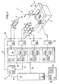
- FIG. 1 shows a schematic perspective view of a sewing machine with an associated control device in a block diagram representation.
- an X-Y table 7 is arranged, which is one in two horizontal coordinate directions, namely the X direction and the Y direction, movable cross slide.
- the X-Y table 7 is formed in the usual way, as for example DE 198 07 771 A1 (corresponding to US 6 095 066 A) is known.
- the X-Y table 7 is driven in the two coordinate directions with the help of electric motors 8, 9, one of which is 8 as an X drive and the other 9 acts as a Y drive.
- the electric motors 8, 9 are are positionable electric motors, usually preferred Stepper motors, or also adjustable DC motors. By both Motors 8, 9 are dependent on their rotational position due to their function controlled control provided so that they each with a rotary position transmitter 10, 11 are provided.
- Such a rotary position transmitter 12 is also arranged as usual on the sewing machine drive motor 4.
- Another electric motor 13 serves as a shift drive for one in the Drawing support plate not shown on the X-Y table 7.
- the Electric motor 13 is specified as a stepper motor that is independent of the rotational position can be controlled. To this extent, this electric motor is 13 no rotary position encoder provided.
- Microprocessor-based control device For the operational control of the sewing machine 1, the one designated as a whole is 20 Microprocessor-based control device is provided. This has a computer part 21 with a master processor as the central component 22 and a non-volatile, resident memory 23. In this so-called Flash memory 23 is the complete control program P for the Sewing machine permanently saved, the various program parts, such as the actual operating program, the corresponding drivers for the peripheral Components, sequence programs for service functions and others Program parts P1 and P2 for components to be discussed in more detail of the control device 20.
- the sewing machine 1 and its control device 20 are operated via a control panel 24 assigned to the master processor 22, the one Display 25 and a keyboard 26 includes.
- the corresponding interface components and drivers for control panel 24 and for communication with this are common in nature and in the drawing omitted for the sake of clarity.
- the control device 20 has a logic module as further basic components 27, a signal processor designated as a whole as 28 and a power section 29 for the actual power control of the motors 4, 8, 9 and 13.
- the logic module 27 contains a volatile memory 30, which with the Program part P1 of the complete control program P from the master processor 22 is charged via a line 31.
- This part of the program P1 includes, for example, logical links for the corresponding ones Switching operations to control motors 4, 8, 9 and 13.
- the signal processor 28 serves to generate the actual control signals to operate motors 4, 8, 9 and 13, which are controlled by drivers 33, 34, 35, 36 of the power section 29 are driven.
- the signal processor 28 itself in turn has a volatile memory 37 in which the program part P2 of the complete control program P via a line 39 from the master processor 22 when the sewing machine control is started up is saved.
- the program part P2 controls the Components of the signal processor in the discussed in more detail below Wise.
- control device 38 for the actual drive motor 4 controlled which is regulated depending on the rotational position.
- the return of the rotary position signal takes place in the manner discussed via the line bundle 32 and the logic module 27.
- the signal processor 28 is provided with a control device 40.1, 40.2, 40.3 for the three motors 8, 9 and 13 provided.
- These control devices 40 are identical, so only the a control device 40.1 will be discussed in more detail.
- this a control part 41.1 which signals corresponding to the rotational position-independent Control of the electric motor 8 generated.
- a control part 42.1 which is arranged parallel to the control part 41.1 and for controlling the connected position-dependent control Electric motor - in this case electric motor 8 - aligned is.
- the signal processor 28 is provided with a control device 40.1, 40.2, 40.3 for the three motors 8, 9 and 13 provided.
- These control devices 40 are identical, so only the a control device 40.1 will be discussed in more detail.
- this a control part 41.1 which signals corresponding to the rotational position-independent Control of the electric motor 8 generated.
- a selection part 43.1 is in the form of a software or hardware realizable OR component the control and 41.1 control part 42.1 assigned to either the control part 41.1 or the control part 42.1 can be coupled in terms of control to the electric motor 8. That's how it looks Selection part 43.1, 43.2 of the two, which are regulated depending on the rotational position Electric motors 8, 9 associated control devices 40.1, 40.2 before that the control parts 42.1, 42.2 activated and for a position-dependent control of the electric motors are responsible.
- the selection part 43.3 has activated the control part 41.3 in order to use the corresponding driver 36, the electric motor 13 regardless of the rotational position to control.
- the selection parts 43.1, 43.2, 43.3 themselves are software via the Program part P2 controlled in the memory module 37 and corresponding to the Selections set selectively.
- the master processor communicates 22 over line 39 to signal processor 28 to provide command or / and exchange setpoint data.
- the control program P only needs to issue the command the control device 40.2 to be changed so that the selection part 43.2 the control part 41.2 is activated.
- the whole Control device 20 can be used unchanged in terms of hardware and software.
- the overall control structure of the control device 20 is preferred implemented on a single (not explicitly shown) board.
- the invention provides a flexible, adaptable, and thus universally applicable control for sewing machines of different Types ready that, depending on the application, drive the sewing machine and - depending on their rotary movement in accordance with a master-slave axis guide -
- Their mode of operation with or without feedback of the rotational position can be set independently of each other in the program.
Landscapes
- Engineering & Computer Science (AREA)
- Textile Engineering (AREA)
- Mechanical Engineering (AREA)
- Computer Hardware Design (AREA)
- Microelectronics & Electronic Packaging (AREA)
- Physics & Mathematics (AREA)
- General Physics & Mathematics (AREA)
- Automation & Control Theory (AREA)
- Sewing Machines And Sewing (AREA)
- Control By Computers (AREA)
Applications Claiming Priority (2)
| Application Number | Priority Date | Filing Date | Title |
|---|---|---|---|
| DE10209317 | 2002-03-02 | ||
| DE10209317A DE10209317A1 (de) | 2002-03-02 | 2002-03-02 | Mikroprozessor-gestützte Steuervorrichtung für eine Nähmaschine |
Publications (3)
| Publication Number | Publication Date |
|---|---|
| EP1348792A2 true EP1348792A2 (fr) | 2003-10-01 |
| EP1348792A3 EP1348792A3 (fr) | 2006-03-22 |
| EP1348792B1 EP1348792B1 (fr) | 2008-04-16 |
Family
ID=27770944
Family Applications (1)
| Application Number | Title | Priority Date | Filing Date |
|---|---|---|---|
| EP03003002A Expired - Lifetime EP1348792B1 (fr) | 2002-03-02 | 2003-02-12 | Dispositif de commande à microprocesseur pour une machine à coudre |
Country Status (8)
| Country | Link |
|---|---|
| US (1) | US6647908B2 (fr) |
| EP (1) | EP1348792B1 (fr) |
| JP (1) | JP2003260279A (fr) |
| KR (1) | KR100510962B1 (fr) |
| CN (1) | CN100480455C (fr) |
| AT (1) | ATE392501T1 (fr) |
| DE (2) | DE10209317A1 (fr) |
| TW (1) | TWI296662B (fr) |
Cited By (2)
| Publication number | Priority date | Publication date | Assignee | Title |
|---|---|---|---|---|
| CN101775712B (zh) * | 2009-12-21 | 2013-02-20 | 苏运松 | 模板夹持布片送料多功能数控缝纫机 |
| ITPD20120083A1 (it) * | 2012-03-19 | 2013-09-20 | Sire Srl | Macchina per cucire con dispositivi di controllo del funzionamento |
Families Citing this family (4)
| Publication number | Priority date | Publication date | Assignee | Title |
|---|---|---|---|---|
| GB0403020D0 (en) * | 2004-02-11 | 2004-03-17 | Pa Consulting Services | Portable charging device |
| JP2007185290A (ja) * | 2006-01-12 | 2007-07-26 | Brother Ind Ltd | ミシン |
| CN103510279A (zh) * | 2013-10-18 | 2014-01-15 | 浙江沪龙电机有限公司 | 花样缝纫机的智能控制系统 |
| US10563332B2 (en) * | 2016-03-28 | 2020-02-18 | Hsuan-Tai CHEN | Closed-loop control device of a mechanical sewing machine and method for controlling the same |
Family Cites Families (10)
| Publication number | Priority date | Publication date | Assignee | Title |
|---|---|---|---|---|
| DE2753087A1 (de) * | 1977-11-29 | 1979-05-31 | Zangs Ag Maschf | Einrichtung zur steuerung der rahmenbewegungen an stick- oder naehautomaten |
| JPS6055148B2 (ja) | 1981-04-10 | 1985-12-03 | 三菱電機株式会社 | 工業用模様縫いミシン |
| US4457242A (en) * | 1981-09-18 | 1984-07-03 | Union Special Corporation | Apparatus for positioning the workholder of an automatic sewing machine |
| DE3540273A1 (de) * | 1984-11-13 | 1986-05-22 | Quick-Rotan Elektromotoren GmbH, 6100 Darmstadt | Naehprozessoranordnung |
| DE3632046C2 (de) | 1986-09-20 | 1993-11-25 | Duerkopp Adler Ag | Verfahren zum Betrieb eines Nähautomaten mit einem Nähkopf mit Drehgehäuse |
| JPH07102262B2 (ja) * | 1989-05-17 | 1995-11-08 | ブラザー工業株式会社 | ミシンの操作装置 |
| CH679872A5 (fr) * | 1989-07-11 | 1992-04-30 | Mefina Sa | |
| KR930008390A (ko) * | 1991-10-25 | 1993-05-21 | 이헌조 | 공조기의 쾌적 제어회로 및 그 방법 |
| DE4416216A1 (de) * | 1994-05-07 | 1995-11-09 | Isel Automation | Vorrichtung zur Steuerung elektrisch betätigter Stellglieder |
| DE19807771C1 (de) * | 1998-02-24 | 1999-04-15 | Duerkopp Adler Ag | Augenknopfloch-Nähmaschine |
-
2002
- 2002-03-02 DE DE10209317A patent/DE10209317A1/de not_active Withdrawn
-
2003
- 2003-02-12 EP EP03003002A patent/EP1348792B1/fr not_active Expired - Lifetime
- 2003-02-12 DE DE50309610T patent/DE50309610D1/de not_active Expired - Lifetime
- 2003-02-12 AT AT03003002T patent/ATE392501T1/de not_active IP Right Cessation
- 2003-02-26 TW TW092104063A patent/TWI296662B/zh not_active IP Right Cessation
- 2003-02-27 US US10/375,234 patent/US6647908B2/en not_active Expired - Fee Related
- 2003-02-28 JP JP2003053485A patent/JP2003260279A/ja active Pending
- 2003-02-28 CN CNB031049540A patent/CN100480455C/zh not_active Expired - Fee Related
- 2003-03-03 KR KR10-2003-0013214A patent/KR100510962B1/ko not_active Expired - Fee Related
Cited By (3)
| Publication number | Priority date | Publication date | Assignee | Title |
|---|---|---|---|---|
| CN101775712B (zh) * | 2009-12-21 | 2013-02-20 | 苏运松 | 模板夹持布片送料多功能数控缝纫机 |
| ITPD20120083A1 (it) * | 2012-03-19 | 2013-09-20 | Sire Srl | Macchina per cucire con dispositivi di controllo del funzionamento |
| WO2013140297A1 (fr) * | 2012-03-19 | 2013-09-26 | Sire Srl | Machine à coudre avec dispositifs de commande de fonctionnement |
Also Published As
| Publication number | Publication date |
|---|---|
| KR100510962B1 (ko) | 2005-08-30 |
| DE10209317A1 (de) | 2003-09-25 |
| JP2003260279A (ja) | 2003-09-16 |
| TW200304973A (en) | 2003-10-16 |
| US20030164128A1 (en) | 2003-09-04 |
| TWI296662B (en) | 2008-05-11 |
| EP1348792B1 (fr) | 2008-04-16 |
| CN100480455C (zh) | 2009-04-22 |
| EP1348792A3 (fr) | 2006-03-22 |
| KR20030072242A (ko) | 2003-09-13 |
| US6647908B2 (en) | 2003-11-18 |
| ATE392501T1 (de) | 2008-05-15 |
| DE50309610D1 (de) | 2008-05-29 |
| CN1442530A (zh) | 2003-09-17 |
Similar Documents
| Publication | Publication Date | Title |
|---|---|---|
| DE2714678C2 (de) | Zierstichnähmaschine | |
| EP0608245B1 (fr) | Dispositif de commande electropneumatique | |
| EP0182281B1 (fr) | Dispositif de processeur pour machine à coudre | |
| DE2610479A1 (de) | Steuervorrichtung fuer werkzeugmaschinen | |
| DE10308386C5 (de) | Identifikation von modularen Maschinenanbauteilen | |
| EP0148281A1 (fr) | Dispositif électronique de commande d'une machine à coudre industrielle | |
| EP2047340A1 (fr) | Module de régulation pour une batterie de valves | |
| DE69513806T2 (de) | Anordnung der steuereinrichtung einer gesteinbohrausrüstung | |
| DE10249092A1 (de) | Fahrzeugsitz, insbesondere für ein Kraftfahrzeug | |
| EP1348792B1 (fr) | Dispositif de commande à microprocesseur pour une machine à coudre | |
| DE102018113404B4 (de) | Vorrichtung zum Spritzgießen von Kunststoffmaterialien | |
| DE2560217C2 (de) | Automatische Nähmaschine | |
| DE3323303A1 (de) | Anordnung fuer den diagnosebetrieb einer elektronisch gesteuerten naehmaschine | |
| EP1335256B1 (fr) | Machine de moulage par injection avec dispositif de contrôle utilisable online | |
| EP0276629B1 (fr) | Machine à coudre | |
| DE19730492A1 (de) | Digitales Typenschild für elektrisch und hydraulisch verstellbare hydrostatische Antriebe | |
| DE102018128116A1 (de) | Bedienpult | |
| EP0259560A2 (fr) | Commande électronique pour commander les vérins d'une machine de traitement de poisson | |
| DE69103488T2 (de) | Steuerungseinrichtung zur Neigung eines Fahrzeugscheinwerfers. | |
| DE10242450A1 (de) | Rundstrickmaschine und eine automatisch laufende Einrichtung zur Mustereinstellung in einer Rundstrickmaschine | |
| DE3337860A1 (de) | Musterzufuehrungs-ausgleichanordnung fuer eine elektronisch gesteuerte naehmaschine | |
| EP0652499A1 (fr) | Dispositif de réglage motorisé pour machines | |
| WO2008055553A1 (fr) | Métier à tricoter | |
| DE102021205491A1 (de) | Verfahren zum Einstellen eines linearen Mehrachssystems und lineares Mehrachssystem | |
| DE102023000680A1 (de) | Bedieneinrichtung zum Bedienen einer Spulvorrichtung |
Legal Events
| Date | Code | Title | Description |
|---|---|---|---|
| PUAI | Public reference made under article 153(3) epc to a published international application that has entered the european phase |
Free format text: ORIGINAL CODE: 0009012 |
|
| AK | Designated contracting states |
Kind code of ref document: A2 Designated state(s): AT BE BG CH CY CZ DE DK EE ES FI FR GB GR HU IE IT LI LU MC NL PT SE SI SK TR |
|
| AX | Request for extension of the european patent |
Extension state: AL LT LV MK RO |
|
| PUAL | Search report despatched |
Free format text: ORIGINAL CODE: 0009013 |
|
| AK | Designated contracting states |
Kind code of ref document: A3 Designated state(s): AT BE BG CH CY CZ DE DK EE ES FI FR GB GR HU IE IT LI LU MC NL PT SE SI SK TR |
|
| AX | Request for extension of the european patent |
Extension state: AL LT LV MK RO |
|
| 17P | Request for examination filed |
Effective date: 20060822 |
|
| AKX | Designation fees paid |
Designated state(s): AT BE BG CH CY CZ DE DK EE ES FI FR GB GR HU IE IT LI LU MC NL PT SE SI SK TR |
|
| GRAP | Despatch of communication of intention to grant a patent |
Free format text: ORIGINAL CODE: EPIDOSNIGR1 |
|
| GRAS | Grant fee paid |
Free format text: ORIGINAL CODE: EPIDOSNIGR3 |
|
| GRAA | (expected) grant |
Free format text: ORIGINAL CODE: 0009210 |
|
| AK | Designated contracting states |
Kind code of ref document: B1 Designated state(s): AT BE BG CH CY CZ DE DK EE ES FI FR GB GR HU IE IT LI LU MC NL PT SE SI SK TR |
|
| REG | Reference to a national code |
Ref country code: CH Ref legal event code: EP |
|
| REG | Reference to a national code |
Ref country code: IE Ref legal event code: FG4D Free format text: LANGUAGE OF EP DOCUMENT: GERMAN |
|
| REF | Corresponds to: |
Ref document number: 50309610 Country of ref document: DE Date of ref document: 20080529 Kind code of ref document: P |
|
| PG25 | Lapsed in a contracting state [announced via postgrant information from national office to epo] |
Ref country code: SI Free format text: LAPSE BECAUSE OF FAILURE TO SUBMIT A TRANSLATION OF THE DESCRIPTION OR TO PAY THE FEE WITHIN THE PRESCRIBED TIME-LIMIT Effective date: 20080416 |
|
| NLV1 | Nl: lapsed or annulled due to failure to fulfill the requirements of art. 29p and 29m of the patents act | ||
| PG25 | Lapsed in a contracting state [announced via postgrant information from national office to epo] |
Ref country code: NL Free format text: LAPSE BECAUSE OF FAILURE TO SUBMIT A TRANSLATION OF THE DESCRIPTION OR TO PAY THE FEE WITHIN THE PRESCRIBED TIME-LIMIT Effective date: 20080416 Ref country code: BG Free format text: LAPSE BECAUSE OF FAILURE TO SUBMIT A TRANSLATION OF THE DESCRIPTION OR TO PAY THE FEE WITHIN THE PRESCRIBED TIME-LIMIT Effective date: 20080716 Ref country code: ES Free format text: LAPSE BECAUSE OF FAILURE TO SUBMIT A TRANSLATION OF THE DESCRIPTION OR TO PAY THE FEE WITHIN THE PRESCRIBED TIME-LIMIT Effective date: 20080727 Ref country code: FI Free format text: LAPSE BECAUSE OF FAILURE TO SUBMIT A TRANSLATION OF THE DESCRIPTION OR TO PAY THE FEE WITHIN THE PRESCRIBED TIME-LIMIT Effective date: 20080416 Ref country code: PT Free format text: LAPSE BECAUSE OF FAILURE TO SUBMIT A TRANSLATION OF THE DESCRIPTION OR TO PAY THE FEE WITHIN THE PRESCRIBED TIME-LIMIT Effective date: 20080916 |
|
| ET | Fr: translation filed | ||
| REG | Reference to a national code |
Ref country code: IE Ref legal event code: FD4D |
|
| PG25 | Lapsed in a contracting state [announced via postgrant information from national office to epo] |
Ref country code: IE Free format text: LAPSE BECAUSE OF FAILURE TO SUBMIT A TRANSLATION OF THE DESCRIPTION OR TO PAY THE FEE WITHIN THE PRESCRIBED TIME-LIMIT Effective date: 20080416 Ref country code: SE Free format text: LAPSE BECAUSE OF FAILURE TO SUBMIT A TRANSLATION OF THE DESCRIPTION OR TO PAY THE FEE WITHIN THE PRESCRIBED TIME-LIMIT Effective date: 20080716 Ref country code: DK Free format text: LAPSE BECAUSE OF FAILURE TO SUBMIT A TRANSLATION OF THE DESCRIPTION OR TO PAY THE FEE WITHIN THE PRESCRIBED TIME-LIMIT Effective date: 20080416 |
|
| PLBE | No opposition filed within time limit |
Free format text: ORIGINAL CODE: 0009261 |
|
| STAA | Information on the status of an ep patent application or granted ep patent |
Free format text: STATUS: NO OPPOSITION FILED WITHIN TIME LIMIT |
|
| PG25 | Lapsed in a contracting state [announced via postgrant information from national office to epo] |
Ref country code: SK Free format text: LAPSE BECAUSE OF FAILURE TO SUBMIT A TRANSLATION OF THE DESCRIPTION OR TO PAY THE FEE WITHIN THE PRESCRIBED TIME-LIMIT Effective date: 20080416 |
|
| 26N | No opposition filed |
Effective date: 20090119 |
|
| PG25 | Lapsed in a contracting state [announced via postgrant information from national office to epo] |
Ref country code: EE Free format text: LAPSE BECAUSE OF FAILURE TO SUBMIT A TRANSLATION OF THE DESCRIPTION OR TO PAY THE FEE WITHIN THE PRESCRIBED TIME-LIMIT Effective date: 20080416 |
|
| BERE | Be: lapsed |
Owner name: DURKOPP ADLER A.G. Effective date: 20090228 |
|
| PG25 | Lapsed in a contracting state [announced via postgrant information from national office to epo] |
Ref country code: MC Free format text: LAPSE BECAUSE OF NON-PAYMENT OF DUE FEES Effective date: 20090228 Ref country code: CY Free format text: LAPSE BECAUSE OF FAILURE TO SUBMIT A TRANSLATION OF THE DESCRIPTION OR TO PAY THE FEE WITHIN THE PRESCRIBED TIME-LIMIT Effective date: 20080416 |
|
| REG | Reference to a national code |
Ref country code: CH Ref legal event code: PL |
|
| GBPC | Gb: european patent ceased through non-payment of renewal fee |
Effective date: 20090212 |
|
| PG25 | Lapsed in a contracting state [announced via postgrant information from national office to epo] |
Ref country code: LI Free format text: LAPSE BECAUSE OF NON-PAYMENT OF DUE FEES Effective date: 20090228 Ref country code: CH Free format text: LAPSE BECAUSE OF NON-PAYMENT OF DUE FEES Effective date: 20090228 |
|
| PGFP | Annual fee paid to national office [announced via postgrant information from national office to epo] |
Ref country code: FR Payment date: 20090217 Year of fee payment: 7 |
|
| PG25 | Lapsed in a contracting state [announced via postgrant information from national office to epo] |
Ref country code: BE Free format text: LAPSE BECAUSE OF NON-PAYMENT OF DUE FEES Effective date: 20090228 |
|
| PG25 | Lapsed in a contracting state [announced via postgrant information from national office to epo] |
Ref country code: GB Free format text: LAPSE BECAUSE OF NON-PAYMENT OF DUE FEES Effective date: 20090212 |
|
| PG25 | Lapsed in a contracting state [announced via postgrant information from national office to epo] |
Ref country code: AT Free format text: LAPSE BECAUSE OF NON-PAYMENT OF DUE FEES Effective date: 20090212 |
|
| PG25 | Lapsed in a contracting state [announced via postgrant information from national office to epo] |
Ref country code: GR Free format text: LAPSE BECAUSE OF FAILURE TO SUBMIT A TRANSLATION OF THE DESCRIPTION OR TO PAY THE FEE WITHIN THE PRESCRIBED TIME-LIMIT Effective date: 20080717 |
|
| REG | Reference to a national code |
Ref country code: FR Ref legal event code: ST Effective date: 20101029 |
|
| PG25 | Lapsed in a contracting state [announced via postgrant information from national office to epo] |
Ref country code: FR Free format text: LAPSE BECAUSE OF NON-PAYMENT OF DUE FEES Effective date: 20100301 |
|
| PG25 | Lapsed in a contracting state [announced via postgrant information from national office to epo] |
Ref country code: LU Free format text: LAPSE BECAUSE OF NON-PAYMENT OF DUE FEES Effective date: 20090212 |
|
| PGFP | Annual fee paid to national office [announced via postgrant information from national office to epo] |
Ref country code: CZ Payment date: 20110203 Year of fee payment: 9 |
|
| PG25 | Lapsed in a contracting state [announced via postgrant information from national office to epo] |
Ref country code: HU Free format text: LAPSE BECAUSE OF FAILURE TO SUBMIT A TRANSLATION OF THE DESCRIPTION OR TO PAY THE FEE WITHIN THE PRESCRIBED TIME-LIMIT Effective date: 20081017 |
|
| PGFP | Annual fee paid to national office [announced via postgrant information from national office to epo] |
Ref country code: TR Payment date: 20120210 Year of fee payment: 10 |
|
| PGFP | Annual fee paid to national office [announced via postgrant information from national office to epo] |
Ref country code: IT Payment date: 20120224 Year of fee payment: 10 |
|
| PGFP | Annual fee paid to national office [announced via postgrant information from national office to epo] |
Ref country code: DE Payment date: 20120425 Year of fee payment: 10 |
|
| PG25 | Lapsed in a contracting state [announced via postgrant information from national office to epo] |
Ref country code: CZ Free format text: LAPSE BECAUSE OF NON-PAYMENT OF DUE FEES Effective date: 20130212 |
|
| REG | Reference to a national code |
Ref country code: DE Ref legal event code: R119 Ref document number: 50309610 Country of ref document: DE Effective date: 20130903 |
|
| PG25 | Lapsed in a contracting state [announced via postgrant information from national office to epo] |
Ref country code: IT Free format text: LAPSE BECAUSE OF NON-PAYMENT OF DUE FEES Effective date: 20130212 |
|
| PG25 | Lapsed in a contracting state [announced via postgrant information from national office to epo] |
Ref country code: DE Free format text: LAPSE BECAUSE OF NON-PAYMENT OF DUE FEES Effective date: 20130903 |
|
| PG25 | Lapsed in a contracting state [announced via postgrant information from national office to epo] |
Ref country code: TR Free format text: LAPSE BECAUSE OF NON-PAYMENT OF DUE FEES Effective date: 20130212 |