EP1348883A2 - Frein à tambour avec dispositif d'ajustement automatique du jeu des patins - Google Patents
Frein à tambour avec dispositif d'ajustement automatique du jeu des patins Download PDFInfo
- Publication number
- EP1348883A2 EP1348883A2 EP03290751A EP03290751A EP1348883A2 EP 1348883 A2 EP1348883 A2 EP 1348883A2 EP 03290751 A EP03290751 A EP 03290751A EP 03290751 A EP03290751 A EP 03290751A EP 1348883 A2 EP1348883 A2 EP 1348883A2
- Authority
- EP
- European Patent Office
- Prior art keywords
- brake
- shoe
- lever
- thermo
- return
- Prior art date
- Legal status (The legal status is an assumption and is not a legal conclusion. Google has not performed a legal analysis and makes no representation as to the accuracy of the status listed.)
- Granted
Links
Images





Classifications
-
- F—MECHANICAL ENGINEERING; LIGHTING; HEATING; WEAPONS; BLASTING
- F16—ENGINEERING ELEMENTS AND UNITS; GENERAL MEASURES FOR PRODUCING AND MAINTAINING EFFECTIVE FUNCTIONING OF MACHINES OR INSTALLATIONS; THERMAL INSULATION IN GENERAL
- F16D—COUPLINGS FOR TRANSMITTING ROTATION; CLUTCHES; BRAKES
- F16D65/00—Parts or details
- F16D65/38—Slack adjusters
- F16D65/40—Slack adjusters mechanical
- F16D65/52—Slack adjusters mechanical self-acting in one direction for adjusting excessive play
- F16D65/54—Slack adjusters mechanical self-acting in one direction for adjusting excessive play by means of direct linear adjustment
- F16D65/546—Slack adjusters mechanical self-acting in one direction for adjusting excessive play by means of direct linear adjustment for mounting within the confines of a drum brake
-
- F—MECHANICAL ENGINEERING; LIGHTING; HEATING; WEAPONS; BLASTING
- F16—ENGINEERING ELEMENTS AND UNITS; GENERAL MEASURES FOR PRODUCING AND MAINTAINING EFFECTIVE FUNCTIONING OF MACHINES OR INSTALLATIONS; THERMAL INSULATION IN GENERAL
- F16D—COUPLINGS FOR TRANSMITTING ROTATION; CLUTCHES; BRAKES
- F16D65/00—Parts or details
- F16D65/38—Slack adjusters
- F16D65/40—Slack adjusters mechanical
- F16D65/52—Slack adjusters mechanical self-acting in one direction for adjusting excessive play
- F16D65/58—Slack adjusters mechanical self-acting in one direction for adjusting excessive play with eccentric or helical body
Definitions
- This invention relates to a drum brake device with an automatic shoe clearance adjustment apparatus, and, more particularly, to a shoe clearance over-adjustment prevention means which suspends automatic shoe clearance adjustment when the temperature within the brake increases and exceeds a predetermined range.
- a drum brake has an automatic shoe clearance adjustment apparatus compensate wear of the brake shoe lining in order to maintain a certain shoe-to-drum clearance.
- the drum brake is repeatedly applied, for example, where if a vehicle is driving down a long downward slope, the temperature of the brake drum increases and thereby expanding the brake drum to cause an apparent shoe-to-drum clearance enlargement, i.e., a temporary enlargement of the shoe-to-drum clearance to the extent of brake drum expansion.
- the automatic shoe clearance adjustment apparatus While the drum brake is expanding, if the automatic shoe clearance adjustment apparatus is configured such that an automatic shoe clearance adjustment functions to adjust the shoe-to-drum clearance, temporarily enlarged because of the brake drum expansion, when the brake drum is cooled and the temperature thereof decreases, this shrinks the brake drum and causes it to return to its normal state, the shoe-to-drum clearance already adjusted during the temporary brake drum expansion remains the same and this can be considered an over-adjustment and may possibly cause a dragging problem.
- the Japanese Patent Publication No. 58-49739 discloses a drum brake with a shoe clearance over-adjustment prevention means.
- An incremental type automatic shoe clearance adjustment apparatus employed in the drum brake of this conventional art is equipped with a shoe clearance adjustment strut which is composed of two, axially detachable members (e.g., a tube and a nut) and a bimetal strip , component of a shoe clearance over-adjustment prevention means, put therebetween.
- a shoe clearance adjustment strut which is composed of two, axially detachable members (e.g., a tube and a nut) and a bimetal strip , component of a shoe clearance over-adjustment prevention means, put therebetween.
- the shoe clearance over-adjustment means cannot be used in most other types of automatic shoe clearance adjustment apparatus, such as one-shot type. It may, however, be used in the incremental type.
- a shoe clearance over-adjustment prevention means of the drum brake in this second conventional art provides a thermo-sensitive member either between a shoe clearance adjustment strut and a brake shoe or between the shoe clearance adjustment strut and a brake lever.
- the shoe clearance over-adjustment prevention means in the structure of the second conventional art can be employed in a one-shot type automatic shoe clearance adjustment apparatus. Therefore, the second conventional art provides an excellent applicability in this regard.
- a typical one-shot type automatic shoe clearance adjustment apparatus comprises a shoe clearance adjustment strut having a strut body, a bell crank adjustment lever, a pin pivoting the adjustment lever on the strut body, a second spring, and a first spring extended between the strut body and first brake shoe. If the amount of outward movement of a pair of brake shoes during the wheel cylinder operation exceeds a predetermined distance, the strut body follows the first brake shoe and a brake lever because of a force of the first spring, and the second brake shoe acts on the adjustment lever to move an engagement position between the adjustment lever and the strut body so as to extend an entire length of the shoe clearance adjustment strut, thereby automatically adjusting a shoe-to-drum clearance.
- the shoe clearance over-adjustment prevention means is characterized in that a thermo-sensitive member is folded thereby creating a folded section and two legs extending therefrom to be folded and facing each other, forming a superposed portion, is inserted between the strut body and the brake lever and that when the service brake operates and the temperature in the brake drum increases and the temperature of the thermo-sensitive member exceeds the predetermined range, the superposed portion of the thermo-sensitive member opens and moves outward to spread the two legs apart from each other against a force of the first spring so as to move the shoe clearance adjustment strut to follow the second brake shoe suspending the automatic shoe clearance adjustment, thereby preventing the over-adjustment.
- thermo-sensitive member requires the force be more than the spring force of the first spring because the superposed portion of the thermo-sensitive member is positioned close to the first spring. Therefore, the thermo-sensitive member needs to be made from a thicker material and must have a wider design.
- thermo-sensitive member Accordingly, weight of the thermo-sensitive member inevitably increases, thereby increasing the cost thereof.
- This invention was made to improve the above-points and is to provide a drum brake with a shoe clearance over-adjustment prevention means, which prevents the shoe clearance over-adjustment because of a lower opening force of the thermo-sensitive member and achieves the objects because of a smaller thermo-sensitive member with a lower cost.
- this invention provides a drum brake device with an automatic shoe clearance adjustment apparatus comprising: a pair of brake shoes facing each other; a service brake actuator positioned between first adjacent ends of the brake shoes; a shoe return inhibitor, for restricting return positions of the brake shoes, positioned adjacent to the service brake actuator and extended between the brake shoes, the shoe return inhibitor automatically displaces the return positions of the brake shoes in the outward direction of the brake shoes when an extent of the outward movement of the brake shoes during the service brake operation exceeds a predetermined distance, wherein a lever element is pivotally supported at first brake shoe in a crossing direction relative to the shoe return inhibitor, one end of the shoe return inhibitor functionally engaging with a position of the lever element between a pivoting section and a free end of the lever element while the free end side of the lever element is supported by the first brake shoe via a thermo-sensitive member; and when the service brake is activated and the temperature of the thermo-sensitive member reaches the predetermined range, a rotational force is applied to the lever element because of
- the lever element is a brake lever for parking brake operation or a radial contraction lever.
- the radial contraction lever supported by the first brake shoe via a supporting member at a free end thereof is provided for contracting the pair of brake shoes because of releasing the supporting member.
- This invention may provide a drum brake device with an automatic shoe clearance adjustment apparatus comprising: a pair of brake shoes facing each other; a service brake actuator positioned between first adjacent ends of the brake shoes; a shoe return inhibitor, for restricting return positions of the brake shoes, positioned adjacent to the service brake actuator and extended between the brake shoes, the shoe return inhibitor automatically displaces the return positions of the brake shoes in the outward direction of the brake shoes when an extent of the outward movement of the brake shoes during the service brake operation exceeds a predetermined distance, wherein a brake lever is pivotally supported at first brake shoe in a crossing direction relative to the shoe return inhibitor, one end of the shoe return inhibitor functionally engaging with a position of the brake lever between a pivoting section and a free end of the brake lever while the free end side of the brake lever is supported by a cable end of a brake cable via a thermo-sensitive member; and when the service brake is activated and the temperature of the thermo-sensitive member reaches the predetermined range, a rotational force is applied to the brake lever because of a thermo-
- thermo-sensitive member at the free end side of the lever allows setting an opening force (force to move two legs of the thermo-sensitive member apart from each other) lower to the magnitude apportioned by the lever-ratio at the position of the thermo-sensitive member, thereby enabling a smaller design for the thermo-sensitive member, thus minimizing material and thereby reducing the cost thereof.
- the lever may be the brake lever for parking brake operation or the radial contraction lever for radial contraction of the pair of the brake shoes because of releasing the supporting member, thereby broadening the applicability thereof to a variety of drum brakes.
- the automatic shoe clearance adjustment apparatus at least has the shoe return inhibitor, for restricting the return positions of the brake shoes and automatically displaces the brake shoes outward in the direction to move themselves apart from each other.
- thermo-sensitive member may be made from a bimetal or a shape memory alloy member, which gives a wider range of material selections depending upon specifications requested.
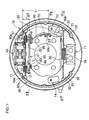
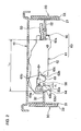
- Example 1 will be explained with reference to Figures 1-4.
- Every one of the brake shoes 20, 30 is slidably supported on a back plate 10 which is fixed on a stationary portion of a vehicle by means of shoe-hold mechanisms 13, 14.
- a brake lever 50 as a parking brake actuator is superposed on the shoe web 22 of the right brake shoe 20 as shown in Figure 1.
- the brake lever 50 is designed to be a plate-like member and such that a proximal portion 50a of the brake lever 50 is pivotally supported at an upper end of the shoe web 22 around a pin 51 and that a free end 50b near the anchor block 11 is connected with a brake cable 52 functioning as a remote-control force transmitting member.
- the brake lever 50 is also bent to form a stopper 50c at a brake inner side near the free end 50b, parallel to an inner end surface of the shoe web 22.
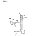
- thermo-sensitive member 70 has a double-folded-leg section, forming a superposed portion which is to be inserted between the stopper 50c and an inner facing surface of the shoe web 22 as shown in Figure 4 so as to restrict a return position of the brake lever 50.
- thermo-sensitive member 70 of this example is a single-piece strip of a bimetal or a shape memory alloy formed by press. This bimetal or shape memory alloy is formed into a first leg 70b and a second leg 70c extending from a folded section 70a to meet each other and are superposed on one another.
- An end of the first leg 70b is curved to form a C-shape clip portion 70d, and the stopper 50c resiliently fits therein.
- thermo-sensitive member 70 may fit on the shoe web 22 instead of the brake lever 50.
- an upper shoe return spring 17 is positioned adjacent to the wheel cylinder 40 while a lower shoe return spring 18 is positioned adjacent to the anchor block 11.
- the upper and lower shoe return springs 17 and 18 stretch between the pair of brake shoes 20 and 30 so as to urge the brake shoes 20 and 30 to approach each other.
- the shoe clearance adjustment strut 61 functioning as a shoe return inhibitor for adjusting a shoe-to-drum clearance is extended adjacent to the wheel cylinder 40 between the shoe web 32 and the brake lever 50.
- the shoe clearance adjustment strut 61 restricts the return positions of the pair of brake shoes 20 and 30 around a point of abutment with the anchor block 11.
- the shoe clearance adjustment strut 61 comprises a plate-like strut body 62, an adjustment lever 63, a pin 64, a second spring 66, and a first spring 65 is added to the shoe clearance adjustment strut 61 to constitute the automatic shoe clearance adjustment apparatus 60.
- the strut body 62 has a notched groove 62a formed at a right side of Figure 2 holding the brake lever 50 and the shoe web 22 therein, and a bottom surface of the groove of the notched groove 62a abuts against the brake lever 50 restricting the return position of the brake shoe 20.
- Second small teeth 62b are formed at left side between both ends of the strut body 62, and an upper side portion above the second small teeth 62b in Figure 2 is bent to form a board thickness stepped portion extending toward the left as shown in Figure 1
- a proximal portion 63a of the adjustment lever 63 is pivotally supported around the left end of the strut body 62 by the pin 64 and is also movable along a longitudinal plate surface of the strut body 62 or in a direction of the outward movement of the left brake shoe 30, and a first small teeth 63c formed on an arcuate end surface of an arm 63b at one side of the adjustment lever 63 engage with a second small teeth 62b of the strut body 62.
- the other arm 63b has a cam 63e, and the cam 63e abuts against an inner surface of a rectangular hole 32a facing outside of the brake to restrict the return position of the brake shoe 30 and positioned in the rectangular hole 32a with a small predetermined gap ⁇ 1 from an inner surface of the rectangular hole 32a at a brake center side.
- the first spring 65 is stretched between the shoe web 22 and the strut body 62 while the second spring 66 is stretched between the strut body 62 and the pin 64 affixed on the adjustment lever 63, both arranged such that a force of the first spring 65 is larger than that of the second spring 66.
- thermo-sensitive member 70 When automatic shoe clearance adjustment is in operation, if the temperature of the thermo-sensitive member 70 reaches the predetermined range, two legs of the thermo-sensitive member 70 tend to move apart from each other to be in an almost V-shape against the spring force of the first spring 65.
- thermo-sensitive member 70 moves the brake lever 50 forward and simultaneously integrally makes the strut body 62 and the adjustment lever 63 follow the brake shoe 30, thereby stopping the automatic shoe clearance adjustment operation and preventing the over-adjustment thereof.
- thermo-sensitive member 70 urges the brake lever 50
- the force on the two legs of the thermo-sensitive member 70 in Figure 1 at least needs to be stronger than a force multiplied by the spring force of the first spring 65 by L 2 / L 1 .
- the thickness of the material of the thermo-sensitive member 70 may be thinner; the width thereof may be smaller; and the weight thereof may be lighter, thereby reducing the cost of the thermo-sensitive member 70.
- Example 2 of the present invention applying a shoe clearance over-adjustment means to an automatic shoe clearance adjustment apparatus employing the same basic structure as in the Japanese Patent Publication No. 43-21822 will be explained with reference to Figures 5-8.
- Example 2 except for the automatic shoe clearance adjustment apparatus 80 and a thermo-sensitive member 71, the same reference numbers used in Example 1 will be assigned to identical parts or sites having the same functions as described in Example 1, and the explanation of the structure and the operation regarding the parts or sites will be omitted here.
- a shoe clearance adjustment strut 81 functioning as the shoe return inhibitor, comprises a strut body 82, an adjustment lever 83, a pawl member 85, two pins 84 and 86, and a second spring 88.
- An automatic shoe clearance adjustment apparatus 80 comprises the shoe clearance adjustment strut 81 and the first spring 87.
- the adjustment lever 83 is superposed on the shoe web 32 of the left brake shoe 30, and a proximal portion 83a is pivotally supported around the upper end of the shoe web 32 by the pin 84, wherein third small teeth 83c are formed on an arcuate end surface on a free end 83b of the adjustment lever 83 extending toward the lower side of the shoe web 32.
- the plate strut body 82 provided adjacent and parallel to the wheel cylinder 40 is designed such that a notched groove 82a, formed at the right end thereof, receives a portion between both ends of the brake lever 50 and the shoe web 22 and that the bottom of the groove in the notched groove supports the brake lever 50. Also, a first spring 87 is stretched between the strut body 82 and the shoe web 22.
- a notched groove 82b formed on the left end of the strut body 82, receives and freely engages a portion between both end of the adjustment lever 83 and the shoe web 32, wherein the bottom of the groove in the notched groove 82b supports the adjustment lever 83.
- a hook 82c formed at a top end of the notched groove 82b is designed such that a predetermined gap ⁇ 2 between a brake inner side of a rectangular hole 83d formed on the adjustment lever 83 and the hook 82c and a gap absorbing a manufacturing tolerance of related-parts between a brake outer side of the rectangular hole 83d and the hook 82c exist.
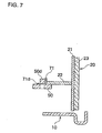
- thermo-sensitive member 71 is designed such that a first leg 71b and a second leg 71c are extending from a folded portion 71a to face and superpose one another and a fitting piece 71d is integrally formed at an intermediate portion of the first leg 71b to be bent in a right angle to extend away from the second leg 71c.
- a bridged stopper 50d is formed, by partial-shearing, in the brake lever 50 at a free end 50b side. As shown in Figure 7, the superposed portion inserted between the inner end surface of the shoe web 22 and a side surface of the bridged stopper 50d, and the fitting piece 71d is press-fit in a gap simultaneously formed the bridged stopper 50d and passing therethrough.
- the strut body 82 and the brake lever 50 follows the brake shoe 20 with the spring force of the first spring 87, and the adjustment lever 83 and the pawl member 85 move together with the brake shoe 30. Therefore, the hook 82c of the strut body 82 abuts against the rectangular hole 83d of the adjustment lever 83 to absorb the gap ⁇ 2 and the adjustment lever 83 rotates counterclockwise in Figure 5 against the spring force of the second spring 88, thereby changing the engaging portion of the third small teeth 83c corresponding to one tooth pitch relative to the small teeth 85a of the pawl section 85.
- the practical effective length of the shoe clearance adjustment strut 81 is extended to maintain an approximately constant shoe-to-drum clearance.
- a lever element in this example is a radial contraction lever 90 functioning to contract the pair of the brake shoes contrary to the parking lever 50 in the above-described Examples 1 and 2. And the radial contraction lever 90 has the over-adjustment prevention means.
- Example 3 An automatic shoe clearance adjustment apparatus in Example 3 has the same fundamental structure described in Example 1, and as in Example 3, the reference number 60 is assigned to the automatic shoe clearance adjustment apparatus of this Example just like Example 1. Further, same reference numbers used in Example 1 will be assigned to identical parts or sites having same functions as described in Example 1, and the explanation of the structure and the operation regarding the parts or sites will be omitted here.
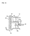
- the plate-like radial contraction lever 90 is superposed on the shoe web 32 of the left brake shoe 30, and a proximal portion 90a is pivotally supported around the upper end of the shoe web 32 by the pin 51, wherein a free end 90b of the radial contraction lever 90 is supported by the shoe web 32 via a superposing section of a thermo-sensitive member 72 and a tongue strip 15b (cited in Figure 10) of a shoe hold spring 15.
- the shoe hold spring 15 is a plate spring in almost U-shape which is designed as shown in Figure 10 to comprise a contacting strip 15a attaching an upper surface of the shoe web 32, a tongue strip 15b extended in an almost right angle from the brake inner side of the contacting strip 15a having a surface at a brake outer side abutting against an inner end surface of the shoe web 32, and a facing strip 15c extended in an almost right angle from the brake outer side of the tongue strip 15b in parallel to a lower surface of the shoe web 32 with a space therebetween, thereby forming an almost U-shaped in cross-section by means of the contacting strip 15a, the tongue strip 15 and the facing strip 15c.
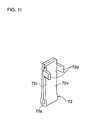
- thermo-sensitive member 72 is designed such that a first leg 72b and a second leg 72c are extending from the folded portion 72a to face and superpose each other and clipping strips 72d where 72d are integrally positioned upper portions of the first leg 72b to be bent in a right angle to extend from both sides thereof opposite toward the second leg 72c, thereby forming almost C-shaped cross-section.
- thermo-sensitive member 72 As shown in Figure 10, the superposed portion of the thermo-sensitive member 72 is inserted between the free end 90b (not cited in Figure 10) of the radial contraction lever 90 and an outer surface of the tongue strip 15b of the shoe hold spring 15, and the hooking strips 72d, 72d catch the radial contraction lever 90.
- the automatic shoe clearance adjustment apparatus 60 of this example is positioned laterally symmetrical to the automatic shoe clearance adjustment apparatus 60 of Example 1, and the shoe clearance adjustment strut 61 is positioned adjacent and parallel to the wheel cylinder 40 and extends between a position between both ends of the radial contraction lever 90 and the brake shoe 20.
- an additional toothed member 67 may be fixed on the strut body 62, and one of hooking portions of the first spring 65 and the second spring 66 are both hooked on the toothed member 67.
- Figure 12 is a structural cross-section view taken along the line XII-XII of Figure 1, and therefore the same reference numbers used in Example 1 will be assigned to identical parts or sites having the same functions as described in Example 1, the explanation of which will be omitted here.
- a pipe member 12 is fixed at a slope on the left side of the back plate 10 and extends toward the outside of the brake.
- the brake cable 52 comprises an inner cable 53, an outer casing 55 and so on.
- a casing cap 56 fixed on one end of the outer casing 55 fits in the pipe member 12 to be clipped by a wire spring clip 19.
- the inner cable 53 slidably positioned within the outer casing 55 has one end inserted in a groove formed at the free end 50b of the brake lever 50 and an end nipple 54 fixed on a top of the inner cable 53 is hooked at the right end side of the free end 50b via a superposed portion of a thermo-sensitive member 73.
- a portion of the brake cable 52 between both ends thereof at an outside of Figure 12 is curved to arrange along a vehicle body such that the other end of the outer casing 55 is fixed on a stationary part of the vehicle and the other end of the inner cable 53 is connected with an operating lever by a driver's seat.
- a return position of the brake lever 50 is restricted by the end nipple 54 of the inner cable 53.
- thermo-sensitive member 73 increases to the predetermined range to open two legs during the service brake operation, the free end 50b of the brake lever 50 moves left, thereby suspending the automatic shoe clearance adjustment operation for preventing the over-adjustment.
- Lever-ratio at a mounting position of the thermo-sensitive member 73 in this example is greater than Examples 1 and 2 of the above-described invention, reducing the magnitude of leg opening force of the thermo-sensitive member 73.
- the brake lever in Example 2 of this invention may be a radial contraction lever as described in Example 3; and an incremental type automatic shoe clearance adjustment apparatus, in which a shoe clearance adjustment strut having a screw-engagement mechanism may be extended between the lever mounted on one brake shoe and the other brake shoe and the adjustment lever sensing the brake shoe movement and automatically extend an entire length of the shoe clearance adjustment strut, may be employed.
- this invention has the following advantages.
- thermo-sensitive member is arranged at a free end side of the lever element, more particularly, between a point against which the shoe clearance adjustment strut abuts the lever and the free end thereof, or at a connecting point with the brake cable for the parking brake lever, which allows to set an opening force (force to move two legs of the thermo-sensitive member apart from each other) lower to the magnitude apportioned by the lever-ratio at the position, which allows the thermo-sensitive member to design to be smaller, thereby reducing the cost thereof.
- At least the lever element is a brake lever for the parking brake operation or a radial contraction lever which functions to enlarge the shoe-to-drum clearance, thereby broadening the applicability thereof to a variety of drum brakes.
- the automatic shoe clearance adjustment apparatus if the amount of the brake shoe movement is more than the predetermined distance, extends the shoe return inhibitor restricting the return position of the brake shoe and automatically moves the return position of the brake shoe to the direction of the outward movement of the brake shoes, thereby broadening the applicability.
- the leg opening force of the thermo-sensitive member is applied larger than the first spring as a component of the one-shot type automatic shoe clearance adjustment apparatus, the leg opening force may be set lower, thereby increasing the effectiveness.
Landscapes
- Engineering & Computer Science (AREA)
- General Engineering & Computer Science (AREA)
- Mechanical Engineering (AREA)
- Braking Arrangements (AREA)
Applications Claiming Priority (2)
| Application Number | Priority Date | Filing Date | Title |
|---|---|---|---|
| JP2002089026 | 2002-03-27 | ||
| JP2002089026A JP3953348B2 (ja) | 2002-03-27 | 2002-03-27 | ドラムブレーキ |
Publications (3)
| Publication Number | Publication Date |
|---|---|
| EP1348883A2 true EP1348883A2 (fr) | 2003-10-01 |
| EP1348883A3 EP1348883A3 (fr) | 2005-03-30 |
| EP1348883B1 EP1348883B1 (fr) | 2006-09-06 |
Family
ID=27800482
Family Applications (1)
| Application Number | Title | Priority Date | Filing Date |
|---|---|---|---|
| EP03290751A Expired - Lifetime EP1348883B1 (fr) | 2002-03-27 | 2003-03-25 | Frein à tambour avec dispositif d'ajustement automatique du jeu des patins |
Country Status (4)
| Country | Link |
|---|---|
| US (2) | US6877589B2 (fr) |
| EP (1) | EP1348883B1 (fr) |
| JP (1) | JP3953348B2 (fr) |
| DE (1) | DE60308081D1 (fr) |
Cited By (3)
| Publication number | Priority date | Publication date | Assignee | Title |
|---|---|---|---|---|
| EP2256362A1 (fr) * | 2009-05-28 | 2010-12-01 | Nisshinbo Brake Inc. | Frein à tambour avec appareil d'ajustement automatique d'espace de chaussure |
| CN102829103A (zh) * | 2011-06-17 | 2012-12-19 | 泰州神力车桥有限公司 | 工程车用左制动器总成 |
| CN115045929A (zh) * | 2022-06-22 | 2022-09-13 | 黄山菲英汽车零部件有限公司 | 一种磨损均匀不偏移的高寿命鼓刹 |
Families Citing this family (18)
| Publication number | Priority date | Publication date | Assignee | Title |
|---|---|---|---|---|
| JP3953348B2 (ja) * | 2002-03-27 | 2007-08-08 | 日清紡績株式会社 | ドラムブレーキ |
| US7350354B2 (en) * | 2004-05-27 | 2008-04-01 | Zf Friedrichshafen Ag | Hydraulic actuation apparatus for a motor vehicle clutch |
| US7481054B2 (en) * | 2004-06-14 | 2009-01-27 | Delphi Technologies, Inc. | Shape memory alloy actuator |
| KR101251109B1 (ko) | 2006-09-18 | 2013-04-04 | 현대자동차주식회사 | 주차 브레이크 구조 |
| DE102007037671A1 (de) * | 2007-08-09 | 2009-02-12 | Lucas Automotive Gmbh | Halteblech für den Handbremshebel einer Trommelbremse bei der Erstmontage zur Erzeugung einer dauerhaften Vorspannung des Bowdenzuges |
| EP2198180B1 (fr) * | 2007-09-05 | 2014-08-27 | Continental Teves AG & Co. oHG | Frein de stationnement à commande électromécanique pour véhicules automobiles et procédé de commande de celui-ci |
| US8720652B2 (en) * | 2008-08-02 | 2014-05-13 | GM Global Technology Operations LLC | Brake retraction utilizing active material actuation |
| US10336270B2 (en) | 2013-10-30 | 2019-07-02 | Toyota Jidosha Kabushiki Kaisha | Vehicle and manufacturing method thereof |
| JP6124020B2 (ja) | 2014-08-29 | 2017-05-10 | トヨタ自動車株式会社 | 車両用帯電電荷低減装置 |
| JP6128093B2 (ja) | 2014-10-16 | 2017-05-17 | トヨタ自動車株式会社 | 車両の吸気装置 |
| JP6160603B2 (ja) | 2014-12-19 | 2017-07-12 | トヨタ自動車株式会社 | 車両の冷却装置 |
| JP6201980B2 (ja) | 2014-12-25 | 2017-09-27 | トヨタ自動車株式会社 | 車両の吸気装置 |
| JP6115559B2 (ja) | 2014-12-26 | 2017-04-19 | トヨタ自動車株式会社 | 車両の排気装置 |
| JP6183383B2 (ja) | 2015-01-13 | 2017-08-23 | トヨタ自動車株式会社 | 車両 |
| JP6365316B2 (ja) | 2015-01-19 | 2018-08-01 | トヨタ自動車株式会社 | 車両の潤滑油又は燃料の供給装置 |
| EP3048017B1 (fr) | 2015-01-23 | 2017-11-08 | Toyota Jidosha Kabushiki Kaisha | Dispositif de génération de force d'amortissement pour véhicule |
| JP6281501B2 (ja) | 2015-01-29 | 2018-02-21 | トヨタ自動車株式会社 | 車両の車輪支持装置 |
| JP6248962B2 (ja) * | 2015-02-10 | 2017-12-20 | トヨタ自動車株式会社 | 車両の制動力発生装置 |
Citations (1)
| Publication number | Priority date | Publication date | Assignee | Title |
|---|---|---|---|---|
| JP2002106620A (ja) | 2000-09-28 | 2002-04-10 | Nisshinbo Ind Inc | ドラムブレーキのシュー間隙過調整防止装置 |
Family Cites Families (19)
| Publication number | Priority date | Publication date | Assignee | Title |
|---|---|---|---|---|
| FR2285545A1 (fr) * | 1974-09-17 | 1976-04-16 | Dba | Dispositif de rattrapage d'usure sensible a la temperature pour frein a tambour |
| GB2049077A (en) * | 1979-05-21 | 1980-12-17 | Lucas Industries Ltd | Automatic adjuster for drum brakes |
| US4476963A (en) * | 1980-12-06 | 1984-10-16 | Lucas Industries Limited | Automatic adjuster for a shoe drum brake |
| DE3115621A1 (de) * | 1981-04-16 | 1982-11-04 | Lucas Industries Ltd., Birmingham, West Midlands | Betaetigungsvorrichtung fuer eine trommelbremse |
| JPS5888236A (ja) * | 1981-11-17 | 1983-05-26 | Akebono Brake Ind Co Ltd | ドラムブレ−キの制動間隙調整装置 |
| DE8427187U1 (de) * | 1984-09-14 | 1985-10-10 | Lucas Industries P.L.C., Birmingham, West Midlands | Selbsttätige Nachstellvorrichtung für eine Bremse |
| US4706784A (en) * | 1985-09-03 | 1987-11-17 | General Motors Corporation | Drum brake adjusters |
| FR2587428B1 (fr) * | 1985-09-19 | 1987-11-27 | Bendix France | Entretoise a reglage automatique, a verrouillage thermique, pour frein a tambour |
| FR2610379B1 (fr) * | 1987-01-29 | 1989-04-21 | Bendix France | Frein a tambour a reglage automatique |
| FR2611011B1 (fr) * | 1987-02-12 | 1994-05-13 | Bendix France | Frein a tambour a reglage automatique verrouille a haute temperature |
| US4808072A (en) * | 1987-09-17 | 1989-02-28 | United Technologies Corporation | Electrical grounding connector for a helicoptor rotor |
| US4938320A (en) * | 1989-01-10 | 1990-07-03 | General Motors Corporation | Apparatus and method of utilization thereof of a thermal compensating self-adjusting vehicle wheel drum brake |
| DE8909618U1 (de) * | 1989-08-10 | 1990-12-06 | Lucas Industries P.L.C., Birmingham, West Midlands | Hydraulisch und mechanisch betätigbare Trommelbremse |
| GB9110513D0 (en) * | 1991-05-15 | 1991-07-03 | Automotive Prod Plc | An adjuster for a brake |
| GB9112350D0 (en) * | 1991-06-08 | 1991-07-31 | Gen Motors France | Drum brake and wear adjuster therefor |
| JPH06193659A (ja) * | 1992-12-21 | 1994-07-15 | Nisshinbo Ind Inc | ドラムブレーキの間隙調整停止装置 |
| JP3728574B2 (ja) * | 1997-06-11 | 2005-12-21 | 日清紡績株式会社 | ドラムブレーキのシュー間隙自動調整装置 |
| IT1308764B1 (it) * | 1999-06-29 | 2002-01-10 | Maff S P A | Compensatore automatico del gioco per un freno a tamburo perautoveicoli |
| JP3953348B2 (ja) * | 2002-03-27 | 2007-08-08 | 日清紡績株式会社 | ドラムブレーキ |
-
2002
- 2002-03-27 JP JP2002089026A patent/JP3953348B2/ja not_active Expired - Fee Related
-
2003
- 2003-03-25 EP EP03290751A patent/EP1348883B1/fr not_active Expired - Lifetime
- 2003-03-25 DE DE60308081T patent/DE60308081D1/de not_active Expired - Lifetime
- 2003-03-27 US US10/401,815 patent/US6877589B2/en not_active Expired - Fee Related
-
2004
- 2004-06-09 US US10/864,178 patent/US7131519B2/en not_active Expired - Fee Related
Patent Citations (1)
| Publication number | Priority date | Publication date | Assignee | Title |
|---|---|---|---|---|
| JP2002106620A (ja) | 2000-09-28 | 2002-04-10 | Nisshinbo Ind Inc | ドラムブレーキのシュー間隙過調整防止装置 |
Cited By (5)
| Publication number | Priority date | Publication date | Assignee | Title |
|---|---|---|---|---|
| EP2256362A1 (fr) * | 2009-05-28 | 2010-12-01 | Nisshinbo Brake Inc. | Frein à tambour avec appareil d'ajustement automatique d'espace de chaussure |
| CN102829103A (zh) * | 2011-06-17 | 2012-12-19 | 泰州神力车桥有限公司 | 工程车用左制动器总成 |
| CN102829103B (zh) * | 2011-06-17 | 2015-01-14 | 泰州神舟传动科技有限公司 | 工程车用左制动器总成 |
| CN115045929A (zh) * | 2022-06-22 | 2022-09-13 | 黄山菲英汽车零部件有限公司 | 一种磨损均匀不偏移的高寿命鼓刹 |
| CN115045929B (zh) * | 2022-06-22 | 2023-11-24 | 黄山菲英汽车零部件有限公司 | 一种磨损均匀不偏移的高寿命鼓刹 |
Also Published As
| Publication number | Publication date |
|---|---|
| DE60308081D1 (de) | 2006-10-19 |
| US20030183465A1 (en) | 2003-10-02 |
| EP1348883B1 (fr) | 2006-09-06 |
| US20060151264A1 (en) | 2006-07-13 |
| JP2003287070A (ja) | 2003-10-10 |
| US7131519B2 (en) | 2006-11-07 |
| US6877589B2 (en) | 2005-04-12 |
| JP3953348B2 (ja) | 2007-08-08 |
| EP1348883A3 (fr) | 2005-03-30 |
Similar Documents
| Publication | Publication Date | Title |
|---|---|---|
| EP1348883B1 (fr) | Frein à tambour avec dispositif d'ajustement automatique du jeu des patins | |
| KR980010001A (ko) | 디스크 브레이크 | |
| EP1473480B1 (fr) | Frein à tambour | |
| EP0836028B1 (fr) | Frein à tambour | |
| US6328141B1 (en) | Drum brake device with automatic shoe clearance adjustment device | |
| US6131708A (en) | Drum brake device | |
| EP1354148B1 (fr) | Dispositif de reglage automatique de freins a tambour, blocable a haute temperature | |
| JP4505121B2 (ja) | ドラムブレーキのシュー間隙過調整防止装置 | |
| EP0952368B1 (fr) | Dispositif de frein à tambour | |
| EP0896167B1 (fr) | Dispositif de frein à tambour | |
| JP4672130B2 (ja) | シュー間隙自動調節機構付きドラムブレーキ | |
| EP1031753B1 (fr) | Disque de frein à double mode de fonctionnement | |
| EP1108916A2 (fr) | Structure de support de câble de frein pour un frein à tambour | |
| EP0905401A2 (fr) | Frein à tambour | |
| JPH08338463A (ja) | ドラムブレーキの間隙自動調整装置 | |
| GB2194300A (en) | Adjuster for drum brakes | |
| JP3553590B2 (ja) | ドラムブレーキアクチュエータ | |
| JPH0449390Y2 (fr) | ||
| JPS5833312Y2 (ja) | ドラムブレ−キ装置の自動間隙調整装置 | |
| EP0258010A2 (fr) | Dispositif automatique de rattrapage du jeu pour frein à tambour | |
| JPS5814254Y2 (ja) | ドラムブレ−キ装置の自動間隙調整装置 | |
| JPS5930268Y2 (ja) | ドラムブレ−キ | |
| JPH09280283A (ja) | ドラムブレーキ装置 | |
| JPH09273572A (ja) | ドラムブレーキ装置 | |
| JPH0734238U (ja) | ドラムブレーキ用自動間隙調整装置 |
Legal Events
| Date | Code | Title | Description |
|---|---|---|---|
| PUAI | Public reference made under article 153(3) epc to a published international application that has entered the european phase |
Free format text: ORIGINAL CODE: 0009012 |
|
| AK | Designated contracting states |
Kind code of ref document: A2 Designated state(s): AT BE BG CH CY CZ DE DK EE ES FI FR GB GR HU IE IT LI LU MC NL PT RO SE SI SK TR |
|
| AX | Request for extension of the european patent |
Extension state: AL LT LV MK |
|
| PUAL | Search report despatched |
Free format text: ORIGINAL CODE: 0009013 |
|
| AK | Designated contracting states |
Kind code of ref document: A3 Designated state(s): AT BE BG CH CY CZ DE DK EE ES FI FR GB GR HU IE IT LI LU MC NL PT RO SE SI SK TR |
|
| AX | Request for extension of the european patent |
Extension state: AL LT LV MK |
|
| 17P | Request for examination filed |
Effective date: 20050708 |
|
| AKX | Designation fees paid |
Designated state(s): DE FR GB |
|
| GRAP | Despatch of communication of intention to grant a patent |
Free format text: ORIGINAL CODE: EPIDOSNIGR1 |
|
| GRAS | Grant fee paid |
Free format text: ORIGINAL CODE: EPIDOSNIGR3 |
|
| GRAA | (expected) grant |
Free format text: ORIGINAL CODE: 0009210 |
|
| AK | Designated contracting states |
Kind code of ref document: B1 Designated state(s): DE FR GB |
|
| REG | Reference to a national code |
Ref country code: GB Ref legal event code: FG4D |
|
| REF | Corresponds to: |
Ref document number: 60308081 Country of ref document: DE Date of ref document: 20061019 Kind code of ref document: P |
|
| PG25 | Lapsed in a contracting state [announced via postgrant information from national office to epo] |
Ref country code: DE Free format text: LAPSE BECAUSE OF FAILURE TO SUBMIT A TRANSLATION OF THE DESCRIPTION OR TO PAY THE FEE WITHIN THE PRESCRIBED TIME-LIMIT Effective date: 20061207 |
|
| ET | Fr: translation filed | ||
| PLBE | No opposition filed within time limit |
Free format text: ORIGINAL CODE: 0009261 |
|
| STAA | Information on the status of an ep patent application or granted ep patent |
Free format text: STATUS: NO OPPOSITION FILED WITHIN TIME LIMIT |
|
| 26N | No opposition filed |
Effective date: 20070607 |
|
| GBPC | Gb: european patent ceased through non-payment of renewal fee |
Effective date: 20070325 |
|
| PG25 | Lapsed in a contracting state [announced via postgrant information from national office to epo] |
Ref country code: GB Free format text: LAPSE BECAUSE OF NON-PAYMENT OF DUE FEES Effective date: 20070325 |
|
| PGFP | Annual fee paid to national office [announced via postgrant information from national office to epo] |
Ref country code: FR Payment date: 20120319 Year of fee payment: 10 |
|
| REG | Reference to a national code |
Ref country code: FR Ref legal event code: ST Effective date: 20131129 |
|
| PG25 | Lapsed in a contracting state [announced via postgrant information from national office to epo] |
Ref country code: FR Free format text: LAPSE BECAUSE OF NON-PAYMENT OF DUE FEES Effective date: 20130402 |