EP1349228A2 - Polymer-Elektrolyt-Brennstoffzelle, ihr Herstellugsverfahren und Kontrollmethode hierzu - Google Patents
Polymer-Elektrolyt-Brennstoffzelle, ihr Herstellugsverfahren und Kontrollmethode hierzu Download PDFInfo
- Publication number
- EP1349228A2 EP1349228A2 EP03251897A EP03251897A EP1349228A2 EP 1349228 A2 EP1349228 A2 EP 1349228A2 EP 03251897 A EP03251897 A EP 03251897A EP 03251897 A EP03251897 A EP 03251897A EP 1349228 A2 EP1349228 A2 EP 1349228A2
- Authority
- EP
- European Patent Office
- Prior art keywords
- electrode
- cell
- electrolyte membrane
- gas
- short
- Prior art date
- Legal status (The legal status is an assumption and is not a legal conclusion. Google has not performed a legal analysis and makes no representation as to the accuracy of the status listed.)
- Ceased
Links
Images





Classifications
-
- H—ELECTRICITY
- H01—ELECTRIC ELEMENTS
- H01M—PROCESSES OR MEANS, e.g. BATTERIES, FOR THE DIRECT CONVERSION OF CHEMICAL ENERGY INTO ELECTRICAL ENERGY
- H01M8/00—Fuel cells; Manufacture thereof
- H01M8/24—Grouping of fuel cells, e.g. stacking of fuel cells
- H01M8/2465—Details of groupings of fuel cells
- H01M8/247—Arrangements for tightening a stack, for accommodation of a stack in a tank or for assembling different tanks
-
- H—ELECTRICITY
- H01—ELECTRIC ELEMENTS
- H01M—PROCESSES OR MEANS, e.g. BATTERIES, FOR THE DIRECT CONVERSION OF CHEMICAL ENERGY INTO ELECTRICAL ENERGY
- H01M4/00—Electrodes
- H01M4/86—Inert electrodes with catalytic activity, e.g. for fuel cells
- H01M4/8605—Porous electrodes
-
- H—ELECTRICITY
- H01—ELECTRIC ELEMENTS
- H01M—PROCESSES OR MEANS, e.g. BATTERIES, FOR THE DIRECT CONVERSION OF CHEMICAL ENERGY INTO ELECTRICAL ENERGY
- H01M4/00—Electrodes
- H01M4/86—Inert electrodes with catalytic activity, e.g. for fuel cells
- H01M4/90—Selection of catalytic material
- H01M4/92—Metals of platinum group
-
- H—ELECTRICITY
- H01—ELECTRIC ELEMENTS
- H01M—PROCESSES OR MEANS, e.g. BATTERIES, FOR THE DIRECT CONVERSION OF CHEMICAL ENERGY INTO ELECTRICAL ENERGY
- H01M4/00—Electrodes
- H01M4/86—Inert electrodes with catalytic activity, e.g. for fuel cells
- H01M4/96—Carbon-based electrodes
-
- H—ELECTRICITY
- H01—ELECTRIC ELEMENTS
- H01M—PROCESSES OR MEANS, e.g. BATTERIES, FOR THE DIRECT CONVERSION OF CHEMICAL ENERGY INTO ELECTRICAL ENERGY
- H01M8/00—Fuel cells; Manufacture thereof
- H01M8/02—Details
- H01M8/0202—Collectors; Separators, e.g. bipolar separators; Interconnectors
- H01M8/0258—Collectors; Separators, e.g. bipolar separators; Interconnectors characterised by the configuration of channels, e.g. by the flow field of the reactant or coolant
-
- H—ELECTRICITY
- H01—ELECTRIC ELEMENTS
- H01M—PROCESSES OR MEANS, e.g. BATTERIES, FOR THE DIRECT CONVERSION OF CHEMICAL ENERGY INTO ELECTRICAL ENERGY
- H01M8/00—Fuel cells; Manufacture thereof
- H01M8/02—Details
- H01M8/0202—Collectors; Separators, e.g. bipolar separators; Interconnectors
- H01M8/0258—Collectors; Separators, e.g. bipolar separators; Interconnectors characterised by the configuration of channels, e.g. by the flow field of the reactant or coolant
- H01M8/026—Collectors; Separators, e.g. bipolar separators; Interconnectors characterised by the configuration of channels, e.g. by the flow field of the reactant or coolant characterised by grooves, e.g. their pitch or depth
-
- H—ELECTRICITY
- H01—ELECTRIC ELEMENTS
- H01M—PROCESSES OR MEANS, e.g. BATTERIES, FOR THE DIRECT CONVERSION OF CHEMICAL ENERGY INTO ELECTRICAL ENERGY
- H01M8/00—Fuel cells; Manufacture thereof
- H01M8/02—Details
- H01M8/0202—Collectors; Separators, e.g. bipolar separators; Interconnectors
- H01M8/0258—Collectors; Separators, e.g. bipolar separators; Interconnectors characterised by the configuration of channels, e.g. by the flow field of the reactant or coolant
- H01M8/0263—Collectors; Separators, e.g. bipolar separators; Interconnectors characterised by the configuration of channels, e.g. by the flow field of the reactant or coolant having meandering or serpentine paths
-
- H—ELECTRICITY
- H01—ELECTRIC ELEMENTS
- H01M—PROCESSES OR MEANS, e.g. BATTERIES, FOR THE DIRECT CONVERSION OF CHEMICAL ENERGY INTO ELECTRICAL ENERGY
- H01M8/00—Fuel cells; Manufacture thereof
- H01M8/02—Details
- H01M8/0202—Collectors; Separators, e.g. bipolar separators; Interconnectors
- H01M8/0267—Collectors; Separators, e.g. bipolar separators; Interconnectors having heating or cooling means, e.g. heaters or coolant flow channels
-
- H—ELECTRICITY
- H01—ELECTRIC ELEMENTS
- H01M—PROCESSES OR MEANS, e.g. BATTERIES, FOR THE DIRECT CONVERSION OF CHEMICAL ENERGY INTO ELECTRICAL ENERGY
- H01M8/00—Fuel cells; Manufacture thereof
- H01M8/02—Details
- H01M8/0271—Sealing or supporting means around electrodes, matrices or membranes
-
- H—ELECTRICITY
- H01—ELECTRIC ELEMENTS
- H01M—PROCESSES OR MEANS, e.g. BATTERIES, FOR THE DIRECT CONVERSION OF CHEMICAL ENERGY INTO ELECTRICAL ENERGY
- H01M8/00—Fuel cells; Manufacture thereof
- H01M8/10—Fuel cells with solid electrolytes
- H01M8/1004—Fuel cells with solid electrolytes characterised by membrane-electrode assemblies [MEA]
-
- H—ELECTRICITY
- H01—ELECTRIC ELEMENTS
- H01M—PROCESSES OR MEANS, e.g. BATTERIES, FOR THE DIRECT CONVERSION OF CHEMICAL ENERGY INTO ELECTRICAL ENERGY
- H01M8/00—Fuel cells; Manufacture thereof
- H01M8/24—Grouping of fuel cells, e.g. stacking of fuel cells
- H01M8/241—Grouping of fuel cells, e.g. stacking of fuel cells with solid or matrix-supported electrolytes
-
- H—ELECTRICITY
- H01—ELECTRIC ELEMENTS
- H01M—PROCESSES OR MEANS, e.g. BATTERIES, FOR THE DIRECT CONVERSION OF CHEMICAL ENERGY INTO ELECTRICAL ENERGY
- H01M8/00—Fuel cells; Manufacture thereof
- H01M8/24—Grouping of fuel cells, e.g. stacking of fuel cells
- H01M8/2457—Grouping of fuel cells, e.g. stacking of fuel cells with both reactants being gaseous or vaporised
-
- H—ELECTRICITY
- H01—ELECTRIC ELEMENTS
- H01M—PROCESSES OR MEANS, e.g. BATTERIES, FOR THE DIRECT CONVERSION OF CHEMICAL ENERGY INTO ELECTRICAL ENERGY
- H01M8/00—Fuel cells; Manufacture thereof
- H01M8/24—Grouping of fuel cells, e.g. stacking of fuel cells
- H01M8/2465—Details of groupings of fuel cells
- H01M8/2483—Details of groupings of fuel cells characterised by internal manifolds
-
- H—ELECTRICITY
- H01—ELECTRIC ELEMENTS
- H01M—PROCESSES OR MEANS, e.g. BATTERIES, FOR THE DIRECT CONVERSION OF CHEMICAL ENERGY INTO ELECTRICAL ENERGY
- H01M4/00—Electrodes
- H01M4/86—Inert electrodes with catalytic activity, e.g. for fuel cells
- H01M4/88—Processes of manufacture
- H01M4/8803—Supports for the deposition of the catalytic active composition
- H01M4/8807—Gas diffusion layers
-
- H—ELECTRICITY
- H01—ELECTRIC ELEMENTS
- H01M—PROCESSES OR MEANS, e.g. BATTERIES, FOR THE DIRECT CONVERSION OF CHEMICAL ENERGY INTO ELECTRICAL ENERGY
- H01M4/00—Electrodes
- H01M4/86—Inert electrodes with catalytic activity, e.g. for fuel cells
- H01M4/88—Processes of manufacture
- H01M4/8825—Methods for deposition of the catalytic active composition
- H01M4/8828—Coating with slurry or ink
- H01M4/8835—Screen printing
-
- H—ELECTRICITY
- H01—ELECTRIC ELEMENTS
- H01M—PROCESSES OR MEANS, e.g. BATTERIES, FOR THE DIRECT CONVERSION OF CHEMICAL ENERGY INTO ELECTRICAL ENERGY
- H01M8/00—Fuel cells; Manufacture thereof
- H01M8/02—Details
- H01M8/0202—Collectors; Separators, e.g. bipolar separators; Interconnectors
-
- Y—GENERAL TAGGING OF NEW TECHNOLOGICAL DEVELOPMENTS; GENERAL TAGGING OF CROSS-SECTIONAL TECHNOLOGIES SPANNING OVER SEVERAL SECTIONS OF THE IPC; TECHNICAL SUBJECTS COVERED BY FORMER USPC CROSS-REFERENCE ART COLLECTIONS [XRACs] AND DIGESTS
- Y02—TECHNOLOGIES OR APPLICATIONS FOR MITIGATION OR ADAPTATION AGAINST CLIMATE CHANGE
- Y02E—REDUCTION OF GREENHOUSE GAS [GHG] EMISSIONS, RELATED TO ENERGY GENERATION, TRANSMISSION OR DISTRIBUTION
- Y02E60/00—Enabling technologies; Technologies with a potential or indirect contribution to GHG emissions mitigation
- Y02E60/30—Hydrogen technology
- Y02E60/50—Fuel cells
-
- Y—GENERAL TAGGING OF NEW TECHNOLOGICAL DEVELOPMENTS; GENERAL TAGGING OF CROSS-SECTIONAL TECHNOLOGIES SPANNING OVER SEVERAL SECTIONS OF THE IPC; TECHNICAL SUBJECTS COVERED BY FORMER USPC CROSS-REFERENCE ART COLLECTIONS [XRACs] AND DIGESTS
- Y02—TECHNOLOGIES OR APPLICATIONS FOR MITIGATION OR ADAPTATION AGAINST CLIMATE CHANGE
- Y02P—CLIMATE CHANGE MITIGATION TECHNOLOGIES IN THE PRODUCTION OR PROCESSING OF GOODS
- Y02P70/00—Climate change mitigation technologies in the production process for final industrial or consumer products
- Y02P70/50—Manufacturing or production processes characterised by the final manufactured product
Definitions
- the present invention relates to a polymer electrolyte fuel cell to be used for a portable power source, an electric vehicle, a cogeneration system, or the like, and also relates to a method of manufacturing the same and inspection method therefor.
- a catalyst layer having, as a main ingredient, a carbon powder carrying a platinum group metal catalyst and having a catalyst function is formed on both major surfaces of a hydrogen ion conductive polymer membrane, which selectively transports hydrogen ions.
- a porous supporting body which is made, e.g., of a carbon cloth, a carbon non-woven fabric, or a carbon paper, and which has both fuel gas permeability and electronic conductivity is provided as a gas diffusion layer on the outside surface of each catalyst layer.
- the combination of the gas diffusion layer and the catalyst layer constitutes an electrode.
- the electrode for the fuel gas is called the fuel electrode or anode, while the electrode for the oxidant gas is called the oxidant electrode or cathode.
- gas sealing members or gaskets which sandwich the polymer electrolyte membrane therebetween, are placed around the electrodes.
- the sealing members or gaskets are preliminarily assembled integrally with the electrodes and the polymer electrolyte membrane.
- the combination of the electrodes and the polymer electrolyte membrane sandwiched between the electrodes is called the electrolyte membrane-electrode assembly (MEA).
- a hot pressing process at about 100 to 150°C is usually used for bonding the catalyst layer and the gas diffusion layer, thereby increasing the handleability in MEA assembling and also increasing the intimate contact between the catalyst layer and the gas diffusion layer.
- the intimate contact increases the gas reactivity and decreases the contact resistance between the layers.
- electrically conductive separator plates are placed for mechanically fixing the MEA and for electrically connecting neighboring MEAs in series.
- Each separator plate is provided, on each surface thereof for contact with the MEA, with a gas flow channel for supplying a reactive gas to the electrode and for carrying away generated gas and excess gas to outside.
- the gas flow channels can be provided separately from the separator plates, but generally the separator plates are provided on the surfaces thereof with gas communication grooves as the gas flow channels.
- a pair of neighboring electrically conductive separator plates having an MEA sandwiched therebetween constitutes a unit cell.
- a fuel cell comprises a cell stack having stacked unit cells.
- a pipe for supplying the fuel gas to pipe branches corresponding to the number of the assembled separator plates In order to supply a fuel gas to the gas flow channel, it is necessary to furcate a pipe for supplying the fuel gas to pipe branches corresponding to the number of the assembled separator plates, and to prepare a piping jig for directly connecting the pipe branches to the gas flow channels of the respective separator plates.
- This jig is called a manifold.
- the type of manifold as described above, in which the supply pipe is directly connected to the gas flow channels is called an outer manifold.
- Another type of manifold, which has a simpler structure is called an inner manifold.
- the inner manifold is of such a type that separator plates having gas flow channels are provided with apertures or through-holes, and the inlets and outlets of the gas flow channels are connected to the apertures, through which the fuel gases are supplied or exhausted.
- a fuel cell generates heat during its operation. Therefore, in order to maintain the fuel cell at an appropriate temperature condition, it is necessary to cool the fuel cell, e.g., by cooling water.
- a cooling unit is provided to be inserted between neighboring separator plates for every 1 to 3 unit cells. An often employed manner is to bond two separator plates, each having a cooling water flow channel on one surface thereof, such that the surfaces thereof each have the cooling water flow channel facing each other, thereby forming a cooling unit.
- Such MEAs, separator plates and cooling units are alternately stacked to a stack of about 10 to 200 cells, thereby forming a cell stack.
- the cell stack is sandwiched by a pair of current collecting plates, insulating plates and end plates in this order, and is then fixed by tightening bolts provided at the end plates to tighten the cell stack.
- This is a general structure of a stack type polymer electrolyte fuel cell.
- a cell stack thereof is usually tightened by a tightening pressure of about 10 to 20 kgf/cm 2 for the purpose of decreasing the contact resistances among the polymer electrolyte membrane, the electrodes and the separator plates, and for ensuring the properties of gas sealing with the gas sealing members or gaskets.
- the end plates are generally composed of mechanically strong metal plates, and the tightening bolts are combined with springs, with or without washers, for applying a sufficient tightening pressure to the cell stack.
- stainless steel which has high resistance to corrosion, is usually used as a material for the end plates, because the end plates partially contact humidified gases and cooling water.
- metal plates having greater electrical conductivity than carbon plates are usually used, and in some cases are subjected to surface treatment for decreasing the contact resistance. Further, since the end plates electrically contact each other through tightening bolts, an insulating plate is inserted between the current collecting plate and the end plate at each end of the cell stack.
- the electrically conductive separator plates to be used for such polymer electrolyte fuel cells need to have a high electrical conductivity, high gas tightness against fuel gases, and high resistance to corrosion, i.e., high resistance to acid, during oxidizing and reducing reactions between hydrogen and oxygen.
- the separator plates are usually made of gas impermeable and dense carbon plates, which are provided with gas flow channels by cutting.
- the separator plates are often made by hot pressing a mixture of a thermosetting resin and a graphite powder placed in a press mold having a convex pattern corresponding to the gas follow channels.
- each metal plate is usually subjected to a noble metal plating, thereby forming a noble metal layer having a sufficient thickness on the surface thereof.
- the catalyst layer is usually bonded to the gas diffusion layer by hot pressing at about 100 to 150°C for increasing the handleability in assembling MEAs and the intimate contact therebetween to realize greater reaction and lower contact resistance.
- the present inventors have found that when such hot pressing is conducted at a greater temperature, e.g., about 130°C, and a high pressure, e.g., of 20 kgf/cm 2 or above, then micro or minor short-circuits between the electrodes are generated in the case of some materials or of surface roughness of the gas diffusion layers used, or in the case of some strengths or thickness of the polymer electrolyte membrane used.
- the slighter such micro short-circuits are, the more difficult it is to find the micro short-circuits during ordinary power generation use of the fuel cell.
- a finding on which the present invention is based is that initial micro short-circuits, which are difficult to find in ordinary use, affect stability or durability of power generation performance of the fuel cell significantly. If micro short-circuits are even slightly present or generated in the initial MEA, an excessively large current flows through the short-circuits. Such current generates heat, and the heat causes the polymer electrolyte in the polymer electrolyte membrane and the electrodes to be thermally decomposed and deteriorated. This causes the short-circuits to become larger as time passes, and thus undesirably promotes the cross leak phenomena. A further finding on which the present invention is based is that such a vicious circle significantly affects the stability or durability of the fuel cell.
- the cell stack is usually tightened with a tightening pressure of about 10 to 20 kgf/cm 2 .
- a tightening pressure of about 10 to 20 kgf/cm 2 .
- Certain technologies of applying a tightening pressure to a fuel cell or cell stack in general are described, e.g., in Japanese Laid-open Patent Publications 2002-203578 and 2002-246044, but they do not teach the technical problems and solutions on which the present invention is based.
- FIG. 6 shows a schematic cross-sectional view of a conceptual or ideal fuel cell.
- a polymer electrolyte membrane 61 is sandwiched at its major surfaces by a pair of electrodes 64, each comprising a catalyst layer 63 and a gas diffusion layer 62, thereby forming an MEA 65.
- the MEA 65 is sandwiched at its major surfaces by a pair of electrically conductive separator plates 66, thereby forming a unit cell as shown.
- all of the polymer electrolyte membrane 61, catalyst layers 63 and gas diffusion layers 62 have uniform thicknesses. There is no such assumption therein that micro short-circuits may be present or generated between the two electrodes.
- gas flow channels 67 in the separator plates 66 maintain their initial conceptual cross-sections.
- FIG. 7 shows a schematic cross-sectional view of a unit cell with the uniformity of each membrane and layer being damaged, thereby causing a micro short-circuit to be present between the two electrodes of MEA in a unit cell.
- gas diffusion layers 72, catalyst layers 73 and a polymer electrolyte membrane 71 are very significantly distorted, with a micro short-circuit 78 being generated.
- gas diffusion layer 72 protrudes or hangs out into a gas flow channel 77 of an electrically conductive separator plate 76.
- the thus protruding gas diffusion layer blocks a part of the gas flow channel, impeding a part of the gas flow, thereby deteriorating the fuel cell performance.
- the present inventors have found that the cross leaks, which have conventionally been considered to be generated only by physical defects in the polymer electrolyte membrane, are also generated by hydrogen dissolved in the polymer electrolyte membrane, which hydrogen diffuses toward the oxidant electrode side and reaches the oxidant electrode due to the concentration gradient of the hydrogen.
- This phenomenon cannot be avoided in principle in the case of a fuel cell using a membrane of, e.g., perfluorocarbon sulfonic acid for the polymer electrolyte membrane. Therefore, this phenomenon needs to be considered separately from the cross leaks attributed to the conventionally considered physical defects of the polymer electrolyte membrane.
- an inspection method is needed such that the factor of cross leaks caused by dissolution and diffusion of hydrogen, which cannot in principle be avoided, is eliminated in inspecting the quality of the fuel cell.
- it has been very difficult to inspect only the cross leaks attributed to physically generated defects in the polymer electrolyte membrane.
- a polymer electrolyte fuel cell comprises a cell stack structure having plural unit cells tightened in the stacking direction, each of the unit cells comprising: an MEA comprising a hydrogen ion conductive polymer electrolyte membrane and a pair of electrodes respectively placed on opposite major surfaces of the electrolyte membrane, each of the electrodes comprising a gas diffusion layer and a catalyst layer; an electrically conductive separator plate contacting one of the electrodes and having a gas flow channel for supplying and exhausting a fuel gas to and from the one electrode; and a further electrically conductive separator plate contacting the other electrode and having a gas flow channel for supplying and exhausting an oxidant gas to and from the other electrode, wherein each of the electrodes is provided with a tightening pressure of about 2 to 4 kgf/cm 2 of the area of each of the electrodes.
- the tightening pressure is such that each of the electrodes is provided with a tightening pressure of about 4 to 8 kgf/cm 2 of the area of each electrode which contacts its respective electrically conductive separator plate, namely of the contact area between the electrode and the separator plate.
- each of the gas flow channels of each of the electrically conductive separator plates have a groove width of about 0.8 mm to 1 mm, and a groove depth of about 0.3 to 1 mm.
- each electrode which contacts its respective electrically conductive separator plate be equal to or greater than the area of the electrode which is out of contact with the electrically conductive separator plates.
- the MEA in a similar polymer electrolyte fuel cell structure, has a short-circuit conductivity of not greater than about 1.5 mS/cm 2 .
- each unit cell comprising an MEA has a hydrogen leak current of not greater than about 3 mA/cm 2 .
- a method of manufacturing a polymer electrolyte fuel cell comprises processes of: forming plural unit cells; stacking the plural unit cells to form a cell stack; and tightening the cell stack in the stacking direction; wherein the process of forming each of the plural unit cells comprises the steps of: placing a pair of electrodes, one on each major surface of a hydrogen ion conductive polymer electrolyte membrane, each electrode comprising a gas diffusion layer and a catalyst layer, thereby forming an MEA; placing an electrically conductive separator plate contacting one of the electrodes and having a gas flow channel for supplying and exhausting a fuel gas to and from the one electrode; and placing a further electrically conductive separator plate contacting the other electrode and having a gas flow channel for supplying and exhausting an oxidant gas to and from the other electrode; wherein the method further comprises an inspection process comprising the steps of: measuring the short-circuit conductivity of each of the MEAs and/or measuring the
- the predetermined value of the short-circuit conductivity be about 1.5 mS/cm 2 and that the predetermined value of the hydrogen leak current be about 3 mA/cm 2 .
- the short-circuit conductivity of each of the MEAs be measured by: applying thereto a constant DC voltage to obtain a steady-state current, or applying a constant DC current to obtain a steady-state voltage; and converting the steady-state current or the steady-state voltage, by calculation, to obtain the short-circuit conductivity.
- the constant DC voltage not be greater than about 0.5 V for each of the MEAs.
- the constant DC current not be greater than about 5 mA/cm 2 of area of electrode of each of the MEAs.
- the step of measuring the short-circuit conductivity of each of the MEAs be conducted by placing the pair of electrodes in a same atmosphere of air or inert gas.
- the step of measuring the hydrogen leak current of each unit cell be conducted by: supplying an inert gas to one of the electrodes and a fuel gas to the other electrode; applying to each of the MEAs a constant DC voltage to obtain a steady-state current, or applying thereto a constant DC current to obtain a steady-state voltage; and converting, by calculation, a difference value by subtracting a value corresponding to the short-circuit conductivity from a value calculated from the steady-state current or the steady-state voltage to yield the hydrogen leak current.
- the inspection process comprise, before the process of forming the cell stack, the steps of: measuring the short-circuit conductivity of each MEA and/or the hydrogen leak current of each unit cell; and removing such MEAs or unit cells that have short-circuit conductivities exceeding the predetermined short-circuit conductivity value or have hydrogen leak currents exceeding the predetermined hydrogen leak current value.
- the inspection process comprise, after the process of forming the cell stack, the steps of: measuring the short-circuit conductivity of each MEA and/or the hydrogen leak current of each unit cell; and removing such MEAs or unit cells or cell stack(s) that have short-circuit conductivities exceeding the predetermined short-circuit conductivity value or have hydrogen leak currents exceeding the predetermined hydrogen leak current value.
- the process of forming the plural unit cells further comprises, before the step of forming each MEA, a step of smoothing both surfaces of each gas diffusion layer.
- an inspection method for a polymer electrolyte fuel cell comprises, before operation of electric power generation of the polymer electrolyte fuel cell, and before or after the process of forming the cell stack, the steps of: measuring the short-circuit conductivity of each MEA and/or the hydrogen leak current of each unit cell; and inspecting to see whether the short-circuit conductivity exceeds a predetermined short-circuit conductivity value, and/or whether the hydrogen leak current exceeds a predetermined hydrogen leak current value.
- a feature of a polymer electrolyte fuel cell according to the present invention is that, with respect to the pressure for tightening stacked unit cells or a cell stack, the tightening pressure per area of each electrode is about 2 to 4 kgf/cm 2 .
- the tightening pressure per area of electrode is less than about 2 kgf/cm 2 , the contact resistances among the polymer electrolyte membrane, the electrodes and the electrically conductive separator plates become high, so that sufficient cell performance cannot be obtained.
- a smoothing treatment namely a treatment of preliminarily reducing roughness and thickness variations of the surface of the gas diffusion layer, has been found to be effective for reducing the influence of the tightening pressure.
- the gas diffusion layer can be subjected, e.g., to preliminary pressing or preliminary flame treatment at the surface thereof.
- micro short-circuits As the micro short-circuits become smaller, it becomes significantly more difficult to find such micro short-circuits under normal use or power generation. Unless they are major short-circuits, they hardly affect initial power generation performance of the fuel cell. However, if micro short-circuits are present, even slightly, in the initial MEA, excessive electric current flows through such micro short-circuits, thereby generating heat. The generated heat thermally decomposes the polymer electrolyte in the polymer electrolyte membrane and the electrodes, whereby the electrolyte deteriorates. This causes the short-circuits to become bigger as time passes. Consequently, cross leak increases, thereby significantly deteriorating the durability of resultant fuel cells. This is a finding on which the present invention is based.
- a feature of a polymer electrolyte fuel cell according to the present invention is that, with respect to the pressure for tightening stacked unit cells, the tightening pressure per contact area between each electrode and each electrically conductive separator plate is about 4 to 8 kgf/cm 2 . More specifically, each electrically conductive separator plate has a gas communication groove or a gas flow channel, which does not contact the electrode, and also has a rib portion which contacts the electrode. The tightening pressure is actually applied or transferred to the electrodes via the rib portions of the separator plates.
- the tightening pressure is transferred to substantially the entire area of the polymer electrolyte membrane via the contact area between the separator plate and the electrode.
- the tightening pressure is basically transferred locally to portions of the polymer electrolyte membrane corresponding to the contact portions between the separator plate and the electrode and via the contact portions between the separator plate and the electrode, and is not transferred evenly to the entire area of the polymer electrolyte membrane. Accordingly, actual pressure applied to portions of the polymer electrolyte membrane, which portions correspond to the contact portions between the separator plate and the electrode, is varied depending on the area ratio between (1) the area corresponding to the contact portions where the separator plate contacts the electrode, and (2) the area corresponding to the non-contact portions where the separator plate is out of contact with the electrode.
- the tightening pressure is preferably determined per contact area between the electrode and the separator plate, rather than per area of the electrode.
- each MEA has a short-circuit conductivity of not greater than about 1.5 mS/cm 2 .
- This short-circuit conductivity can be more specifically expressed by short-circuit conductivity attributed to the DC resistance component between the fuel electrode and the oxidant electrode of the unit cell. It has been found that even though micro short-circuits are present in an MEA, or are generated in the MEA by hot pressing the MEA or by tightening the cell stack, such micro short-circuits hardly affect the resultant durability of the fuel cell, if the short-circuit conductivity of the MEA is not greater than about 1.5 mS/cm 2 , more preferably not greater than about 1 mS/cm 2 .
- the short-circuit conductivity of the MEA is preferably measured by: applying thereto a constant DC voltage to obtain a steady-state current, or applying a constant DC current to obtain a steady-state voltage; and converting the steady-state current or the steady-state voltage, by calculation, to the short-circuit conductivity.
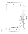
- the steady-state current and the steady-state voltage are explained in the following. As will be described later with reference to FIG. 13 and FIG. 14, when a constant DC voltage or a constant DC current is applied across the electrodes of the MEA, the current or the voltage between the two electrodes abruptly varies during an initial time period after the application of such DC voltage or DC current.
- steady-state current and steady-state voltage are attributable to a DC resistance component alone of the MEA or between the two electrodes of the unit cell. Dividing the applied DC voltage by the measured steady-state current, or dividing the measured steady-state voltage by the applied DC current, the resistance of the MEA is obtained. The inverse or reciprocal value of such resistance per unit area of the electrode can thus be calculated and is the short-circuit conductivity of the MEA.
- the constant DC voltage applied not be greater than about 0.5 V, more preferably about 0.2 V, per MEA or unit cell, and that the constant DC current applied not be greater than about 5 mA/cm 2 , more preferably about 2 mA/cm 2 , of area of each electrode.
- the MEA in order to measure the short-circuit conductivity attributed to DC resistance alone, the MEA should be prevented, as much as possible, from generating an electrochemical reaction.
- electrochemical reaction in the measurement there should be no difference in partial pressure of hydrogen gas and oxygen gas between the two electrodes of the MEA.
- inert gas such as nitrogen is preferable.
- atmosphere can be air.
- DC voltage or DC current can be applied to the MEA, which is exposed to air and sandwiched by separator plates capable of collecting current.
- neither the MEA nor the gas supplied to the MEA contain water, because when a polymer electrolyte does not contain water, the ionic conductivity of the electrolyte is low, so that electrochemical reaction barely occurs.
- a feature of the polymer electrolyte fuel cell is that each unit cell comprising an MEA has a hydrogen leak current of not greater than about 3 mA/cm 2 , preferably not greater than about 2 mA/cm 2 . It has been found that when such hydrogen leak current is not greater than about 3 mA/cm 2 , the durability or stable long-term operation of the resultant fuel cell is hardly affected by the hydrogen leak current. Further, the hydrogen leak current value caused by dissolution of hydrogen gas alone into the polymer electrolyte membrane having no physical defects has been found to be about 1 to 2 mA/cm 2 . It has thus been found that when the value is not greater than about 2 mA/cm 2 , the influence of the hydrogen leak current further decreases.
- the hydrogen leak current of each unit cell be measured by: supplying an inert gas to one of the electrodes of the MEA and a fuel gas to the other electrode; applying to each of the MEAs a constant DC voltage to obtain a steady-state current, or applying thereto a constant DC current to obtain a steady-state voltage; and converting, by calculation, a difference value obtained by subtracting a value corresponding to the short-circuit conductivity from a value calculated from the steady-state current or the steady-state voltage, to yield the hydrogen leak current.
- a steady-state current or a steady-state voltage is obtained.
- the total conductivity calculated from the steady-state current or the steady-state voltage includes both the conductivity attributed to micro short-circuits and the hydrogen leak current value, more precisely the conductivity corresponding to the hydrogen leak current value.
- a conductivity difference is obtained. Re-converting, by calculation, the conductivity difference to a current value per area of electrode of unit cell, the hydrogen leak current can be obtained.
- each gas flow channel of each separator plate have a groove width of about 0.8 mm to 1 mm, and a groove depth of about 0.3 to 1 mm.
- the groove width is greater than about 1 mm, particularly in the case of soft gas diffusion layers, e.g., of carbon cloth, the gas diffusion layer is likely to hang out or protrude into each groove or gas follow channel.
- the groove width is smaller than about 0.8 mm, the resultant amount of gas flow in each groove or gas flow channel may become undesirably insufficient.
- each separator plate is likely to become too weak. In order to increase the strength of each separator plate having such large groove depth, it becomes necessary to make each separator plate overly thick.
- the term "groove width” is used to mean average width of groove.
- the groove width is constant from the top surface of the groove to the bottom surface of the groove. So, when the groove width is described as being, e.g., 1.0 mm, it is 1.0 mm from the top to the bottom of the groove.
- the groove having a groove width of 1.0 mm can have a top surface width greater than 1.0 mm (e.g. 1.1 mm) and a bottom surface width less than 1.0 mm (e.g. 0.9 mm) as long as the average groove width is 1.0 mm.
- each electrically conductive separator plate and each electrode it is preferred that the area of each electrode which contacts each separator plates be equal to or greater than the area of each electrode which is out of contact with each separator plate.
- This non-contact or contact between the electrode and the separator plate is primarily attributed to the separator surface having the groove portions or gas flow channel portions and to rib portions, respectively.
- the contact area relation as described above is satisfied, particularly in the case of soft gas diffusion layers, e.g., of carbon cloth, it becomes easier to prevent each gas diffusion layer from hanging out or protruding into each gas follow channel, and to evenly sandwich the entire area of each electrolyte membrane by each pair of electrodes.
- separator plates having a relatively low electric conductivity or high resistance without significantly affecting the resultant fuel cell performance due to the relatively low conductivity or high resistance of the separator plate.
- a feature thereof is that the method comprises an inspection process comprising the steps of: measuring the short-circuit conductivity of each MEA and/or the hydrogen leak current of each unit cell; and removing such MEAs or such unit cells or such cell stack(s) that have short-circuit conductivities exceeding a predetermined short-circuit conductivity value or have hydrogen leak currents exceeding a predetermined hydrogen leak current value.
- predetermined short-circuit conductivity value be about 1.5 mS/cm 2 and such predetermined hydrogen leak current value be about 3 mA/cm 2 .
- fuel cells can be efficiently manufactured by conducting the inspection process before the process of forming the cell stack, and by removing such MEAs or such unit cells that have short-circuit conductivities exceeding the predetermined short-circuit conductivity value or have hydrogen leak currents exceeding the predetermined hydrogen leak current value.
- fuel cells can still be efficiently or conveniently manufactured by removing such MEAs or such unit cells or such cell stack(s) that have short-circuit conductivities exceeding the predetermined short-circuit conductivity value or have hydrogen leak currents exceeding the predetermined hydrogen leak current value.
- pre-shipment inspection can then be easily conducted without the need for measurements of fuel cell performance using actual operation of the fuel cells, which has conventionally been needed.
- the present Example 1 will be described with reference to FIGS. 1A, 1B, 2A, 2B, 3A, 3B, 4, 5 and 10.
- An acetylene black powder carrying 25 wt% of platinum particles having an average particle size of 3 nm was prepared as a catalyst for the electrodes.
- An ethyl alcohol dispersion of a perfluorocarbon sulfonic acid powder was mixed with a solution of isopropanol having this catalyst powder dispersed therein, thereby forming a catalyst paste.
- An electrode was thereby made of a carbon paper with a catalyst layer formed thereon.
- an adjustment was made so that the thus-made electrode contained 0.3 mg/cm 2 of platinum, and 1.2 mg/cm 2 of perfluorocarbon sulfonic acid.
- a pair of such electrodes was bonded, by hot pressing at a temperature of 130°C and a pressure of 3 kgf/cm 2 , on a front surface and a rear surface, respectively, of a proton conductive polymer electrolyte membrane having an outer dimension of 10 cm ⁇ 26 cm in such a manner that the catalyst layers of the electrodes were brought into contact with the opposite major surfaces of the electrolyte membrane, thereby forming an electrolyte membrane-electrode assembly (MEA).
- the proton conductive polymer electrolyte membrane used here was made by using a perfluorocarbon sulfonic acid, and was formed to a thin film having a thickness of 50 ⁇ m.
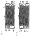
- FIG. 1A and FIG. 1B are schematic plan views showing an electrically conductive separator plate as used in the present Example, showing a front surface and a rear surface thereof, respectively, which have, e.g., grooves for gas communication, namely gas flow channel.
- This separator plate was made by cutting a dense and gas-impermeable isotropic graphite (glass-like carbon) plate.
- FIG. 1A shows configurations of oxidant gas communication grooves or flow channel
- FIG. 1B shows configurations of fuel gas communication grooves or flow channel.
- the separator plate had a dimension of 10 cm ⁇ 26 cm, and a thickness of 2 mm.
- Grooves 11a, 11b are each concave portions having a width of 1.0 mm and a depth of 0.7 mm for the reactive gases to communicate therethrough, respectively.
- rib portions 12a, 12b between the gas flow channels are each convex portions having a width of 1.2 mm, with the surfaces thereof being the surfaces of the separator plate.
- the separator plate had, formed therein, manifold holes (inlet 13a, outlet 13b) for oxidant gas, manifold holes (inlet 14a, outlet 14b) for fuel gas, and manifold holes (inlet 15a, outlet 15b) for cooling water.
- FIGS. 1A and 1B As will be described later, in sandwiching an MEA between two separator plates each as shown in FIGS. 1A and 1B for making a unit cell, the rear surface, FIG. 1B, of one of the separator plates was placed to face the front surface, FIG. 1A, of the other separator plate, with the MEA being sandwiched therebetween.
- the respective elements such as gas communication grooves on the opposite surfaces of the separator plate were designed to be correspondingly positioned and have the same shapes and sizes, thereby enabling matching for the sandwiching.
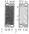
- FIG. 2A and FIG. 2B are schematic plan views showing a further electrically conductive separator plate as used in the present Example, showing a front surface and a rear surface thereof, respectively.
- FIG. 2A shows configurations of oxidant gas communication grooves or flow channels formed on the front surface of the separator plate as in FIG. 1A
- FIG. 2B shows configurations of a cooling water flow channel formed on the rear surface thereof for flowing a cooling water therethrough.
- the separator plate as shown in FIGS. 2A and 2B was so designed to have manifold holes (inlet 25a, outlet 25b) for cooling water positioned at locations corresponding to the manifold holes 15a, 15b for cooling water of FIGS. 1A and 1B, respectively.
- the former manifold holes were so designed to have the same size and shape corresponding to those of the latter manifold holes.
- the sizes and shapes as well as the positions of other manifold holes for gas communication (oxidant gas inlet 23a and outlet 23b; fuel gas inlet 24a and outlet 24b) were designed to be the same as and correspond to those of the manifold holes for gas communication in the separator plate as shown in FIGS. 1A and 1B.
- Reference numeral 21 designates a concave-shaped portion or groove for flowing cooling water from the inlet 25a.
- the depth of the groove was 0.5 mm.
- Reference numeral 22 designates convex-shaped portion or rib between the groove sections of the groove 21. The rib is a portion of the separator plate having remained by the cutting machining for the groove 21.
- the cooling water flows into the groove from the inlet 25a, and reaches the outlet 25b.
- FIGS. 3A and 3B are schematic plan views showing a still further electrically conductive separator plate as used in the present Example, showing a front surface and a rear surface thereof, respectively.
- FIG. 3A shows configurations of a cooling water flow channel
- FIG. 3B shows configurations of a fuel gas flow channel.
- the size and shape as well as the positions of manifold holes for cooling water communication were designed to be the same as and correspond to those of the manifold holes 15a, 15b for cooling water communication in the separator plate as shown in FIGS. 1A and 1B.
- manifold holes for gas communication were designed to be the same as and correspond to those of the manifold holes for gas communication in the separator plate as shown in FIGS. 1A and 1B.
- Reference numeral 31 designates a concave-shaped portion or groove for flowing cooling water from the inlet 35a.
- the depth of the groove was 0.5 mm.
- Reference numeral 32 designates a convex-shaped portion or rib between the groove sections of the groove 31. The rib is a portion of the separator plate remaining from the machining for the groove 31.
- the cooling water flows into the groove from the inlet 35a, and reaches the outlet 35b.
- an electrically conductive separator plate unit having a cooling water unit therein was made by combining one separator plates as shown in FIGS. 2A, 2B and a further separator plate as shown in FIGS. 3A, 3B in a manner that the rear surface, FIG. 2B, of the one separator plate was placed to face and bonded with the front surface, FIG. 3A, of the further separator plate.
- the respective elements such as the cooling water grooves and ribs on the surface of the one separator plate as shown in FIG. 2B were designed to be correspondingly positioned and have the same shapes and sizes as those of the further separator plate as shown in FIG. 3A, thereby enabling matching for the face to face bonding.
- sealing members for gaskets were used. More specifically, O-ring-like sealing members made of VitonTM (product of DuPont Dow Elastomer Japan) being an elastic body, each sealing member having a circular or ellipse cross-section, were placed on surfaces of separator plates at places close to the peripheries of, and in a manner to encircle, the gas communication grooves, the cooling water channels and the manifold holes. These sealing members are shown in such drawings FIG. 1A to FIG.
- sealing members were placed at corresponding positions at facing surfaces of each pair of separator plates for forming each unit cell and cooling water unit, so that the thus facing sealing members in each pair of separator plates were either indirectly pressed to each other with a polymer electrolyte membrane therebetween at certain places, or directly pressed to each other at other places. Consequently, such sealing members in combination with surfaces of separator plates supporting the sealing members constituted gaskets having a sealing function.
- O-ring-like sealing member in the "O-ring-like" sealing member is used herein to express that the sealing member has a ring or loop shape corresponding to the shape of the portion to be encircled and sealed thereby, and that the sealing member has a cross-section of a circle or an ellipse.
- a separator plate as shown in FIGS. 2A, 2B was combined with a separator plate as shown in FIGS. 3A, 3B in a manner that the surface as shown in FIG. 2B was placed to face the surface as shown in FIG. 3A, so that the ribs and grooves of one surface face those of the other surface, and also that O-ring-like sealing members on the two facing surfaces face and are pressed to each other.
- an electrically conductive adhesive was used for bonding each O-ring-like sealing member to its supporting surface on each electrically conductive separator plate.
- each proton conductive polymer electrolyte membrane of each prepared MEA was provided with manifold holes for flowing cooling water, fuel gas and oxidant gas.
- FIG. 4 shows a front surface of an MEA.
- reference numeral 40 designates an electrode such as a fuel electrode
- reference numeral 41 designates a proton conductive polymer electrolyte membrane.
- the polymer electrolyte membrane 41 was provided with manifold holes (inlet 43a and outlet 43b) for oxidant gas, manifold holes (inlet 44a and outlet 44b) for fuel gas, and manifold holes (inlet 45a and outlet 45b) for cooling water.
- the sizes and shapes as well as the positions of these manifold holes were designed to be the same as and correspond to those respective manifold holes in the separator plates as shown in FIG. 1A to FIG. 3B.
- the rear surface of the MEA was also provided with an electrode, such as an oxidant electrode, and all six manifold holes pass through to the rear surface as well.
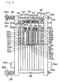
- FIG. 5 is a schematic front view of such fuel cell, wherein the upper part is a schematic cross-sectional view cut by a plane which is parallel to the length of the fuel cell or perpendicular to each separator plate, and which passes through the center of each manifold hole of the fuel gas inlet.
- reference numeral 501 designates an electrically conductive separator plate having a planar surface at a front surface thereof and having, at a rear surface thereof, a surface as shown in FIG. 2B, where a cooling water flow channel and respective manifold holes are formed.
- Reference numeral 502 designates an electrically conductive separator plate having, at a front surface thereof, a surface as shown in FIG.
- FIG. 3A where a cooling water flow channel and respective manifold holes are formed, and having, at a rear surface thereof, a surface as shown in FIG. 3B, where a fuel gas flow channel and respective manifold holes are formed.
- These two separator plates are bonded to each other, with O-ring-like gas sealing members 527, 537a placed on the respective separator plates being pressed to each other, thereby forming a cooling water unit having a cooling water flow channel 511 by or between the two separator plates, and also forming a part of a fuel gas manifold 554 which penetrates the cell stack.
- gas sealing members 527 and 537a for encircling and sealing the fuel gas manifold 554 are partially shown.
- Reference numeral 503 is an electrically conductive separator plate having, at a front surface thereof, a surface as shown in FIG. 1A where an oxidant gas flow channel and respective manifold holes are formed, and having, at a rear surface thereof, a surface as shown in FIG. 1B where a fuel gas flow channel and respective manifold holes are formed.
- an MEA as shown in FIG. 4 is sandwiched, the MEA comprising electrodes 540a, 540b sandwiching a polymer electrolyte membrane 541 having respective manifold holes.
- the electrode 540a faces and contacts a fuel gas flow channel 521
- the electrode 540b faces and contacts an oxidant gas flow channel 531a, thereby forming a unit cell also having a part of the fuel gas manifold 554.
- gas sealing members 537b, 547a which are placed on the separator plates for encircling the fuel gas manifold 554, and which are pressed to each other indirectly via the polymer electrolyte membrane 541, are partially shown.
- Reference numeral 504 is an electrically conductive separator plate having, at a front surface thereof, a surface as shown in FIG. 2A where an oxidant gas flow channel and respective manifold holes are formed, and having, at a rear surface thereof, a surface as shown in FIG. 2B where a cooling water flow channel and respective manifold holes are formed.
- an MEA as shown in FIG. 4 is sandwiched, the MEA comprising electrodes 550a, 550b sandwiching a polymer electrolyte membrane 551 having respective manifold holes.
- the electrode 550a faces and contacts a fuel gas flow channel 531b
- the electrode 550b faces and contacts an oxidant gas flow channel 561, thereby forming a unit cell also having a part of the fuel gas manifold 554.
- gas sealing members 547b, 557a which are placed on the separator plates for encircling the fuel gas manifold 554, and which are pressed to each other indirectly via the polymer electrolyte membrane 551, are partially shown.
- Reference numeral 505 is an electrically conductive separator plate having, at a front surface thereof, a surface as shown in FIG. 3A where a cooling water flow channel and respective manifold holes are formed, and having a planar rear surface.
- the separator plate 504 and the separator plate 505 are bonded to each other each other, with O-ring-like gas sealing members 557b, 567 placed on the respective separator plates being pressed to each other, thereby forming a cooling water unit having a cooling water flow channel 571 by or between the two separator plates, and also forming a part of a fuel gas manifold 554 which penetrates the cell stack.
- gas sealing members 557b and 567 for encircling and sealing the fuel gas manifold 554 are partially shown.
- a fuel gas is introduced from a fuel gas introduction pipe 554a welded to the end plate 583a, and is injected into the fuel gas manifold 554, which is an integration of the above-described parts of the fuel gas manifold.
- the injected fuel gas flows through fuel gas flow channels of the separator plates, and is exhausted to outside of the fuel cell through a fuel gas exhaust pipe 554b welded to the end plate 583b.
- the above description mainly refers to the upper part as shown by the cross-sectional view in FIG. 5.
- the lower part as shown by the front view in FIG. 5 has a structure similar to the upper part, although detailed description therefor is omitted here, except for the following brief description. That is, in the lower part, an oxidant gas is introduced from an oxidant gas introduction pipe 553a welded to the end plate 583a, and is injected into an oxidant gas manifold being formed to penetrate the separator plates. The oxidant gas flows through oxidant gas flow channels of the separator plates, and is then exhausted to outside of the fuel cell through an oxidant gas exhaust pipe 553b welded to the end plate 583b.
- the stacked assembly as formed above is fixed by tightening members provided at four corners at each outer surface of each end plate. More specifically, through-holes are respectively provided at the four corners of each end plate. A tightening rod is provided to each such through-hole, and is provided with a bolt and a spring at an end thereof, and with a nut at the other end thereof, whereby a tightening pressure can be applied to the stacked assembly.
- a tightening rod is provided to each such through-hole, and is provided with a bolt and a spring at an end thereof, and with a nut at the other end thereof, whereby a tightening pressure can be applied to the stacked assembly.
- FIG. 5 two each of such four kinds of tightening members are shown, namely bolts 592a, 595a, springs 593, 596 (with or without washers), tightening rods 591, 594 and nuts 592a, 595b.
- the two each of such four kinds of tightening members are designed to have their centers positioned on the cross-sectional plane as shown by the cross-sectional view with respect to the upper part of FIG. 5.
- a two- cell-stacked polymer electrolyte fuel cell according to the present Example was made.
- the present specification including the present Example and other Examples refer to tightening pressure per area of the electrode and to tightening pressure per contact area of the electrode and the electrically conductive separator plate.
- Such tightening pressures can be measured by using a pressure sensor, but can also be obtained by using calculations as well. This will be described below.
- tightening load of each sealing member or gasket can be obtained, by calculation, from the elastic recovery force of the sealing member, wherein the elastic recovery force can alternatively be expressed by compression recovery force or reactive force. Subtracting this tightening load of the sealing member from the total tightening load applied to the cell stack, the tightening load applied to the electrode can be obtained. Further, dividing the thus calculated tightening load by the area of the electrode, the tightening pressure per area of the electrode can be obtained by such calculation.
- the total tightening load and the elastic recovery force of the sealing member can be obtained as follows.
- the total tightening load of the cell stack can be calculated by multiplying the spring constant by the elastic shrinkage amount or compression amount of the spring.
- the elastic recovery force of the sealing member can be calculated as follows on the assumption that all the sealing members used have the same elastic shrinkage property.
- the shrinkage (compression) amount of the sealing member is so designed that each electrically conductive separator plate contacts each electrode with an optimum load when the sealing member shrinks by a certain shrinkage amount. More specifically, the design is made with known design parameters to control the pressure applied to the respective elements, such as the electrodes, by the shrinkage amount of each sealing member. Based on such design parameters, the elastic recovery force of the sealing member can be calculated when the sealing member shrinks with the certain shrinkage amount.
- the shrinkage amount of the sealing member can be calculated as follows. That is, subtracting the length between the two end separator plates of the cell stack, after the tightening of the cell stack, from the corresponding length between the two end separator plates of the cell stack before the tightening, namely free length, the total shrinkage amount of the sealing members can be obtained. Since the cell stack has plural layers of sealing members, the total shrinkage amount of the sealing members is the sum of the shrinkage amounts of respective layers of sealing members. Accordingly, dividing the total shrinkage amount of the sealing members by the number of layers of sealing members, the shrinkage amount of the sealing member per layer of sealing members can be obtained.
- the tightening load applied to the electrode can be calculated.
- the tightening pressure per area of the electrode can be obtained.
- the tightening pressure per contact area between the electrode and the separator plate can be obtained.
- the fuel cell according to the present Example was kept at 70°C, wherein a hydrogen-containing gas consisting of 80% hydrogen, 20 % carbon dioxide gas and 10 ppm carbon monoxide gas and being humidified and heated to have a dew point of 68.5°C was supplied to the fuel electrode, and air humidified and heated to have a dew point also of 70°C was supplied to the oxidant electrode of the fuel cell.
- a hydrogen-containing gas consisting of 80% hydrogen, 20 % carbon dioxide gas and 10 ppm carbon monoxide gas and being humidified and heated to have a dew point of 68.5°C was supplied to the fuel electrode, and air humidified and heated to have a dew point also of 70°C was supplied to the oxidant electrode of the fuel cell.
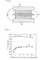
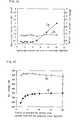
- FIG. 9 shows the results of such measurements per one unit cell of the fuel cell.
- V0 designates a characteristic curve of the open-circuit voltage
- V1 designates a characteristic curve of the cell voltage during power generation at a current density of 0.3 A/cm 2 .
- the open-circuit voltage V0 was not significantly affected by the tightening pressure, and started gradually decreasing when a tightening pressure was increased to about 6 kgf/cm 2 or more.
- the cell voltage V1 during power generation was significantly affected by the tightening pressure.
- the tightening pressure exceeded 2 kgf/cm 2 , the cell voltage started gradually increasing, and at a tightening pressure of about 6 kgf/cm 2 , it became substantially saturated. It has been found therefrom that the tightening pressure per area of electrode needs to be not lower than about 2 kgf/cm 2 .
- the two-cell-stacked fuel cell according to the present Example was kept at 70°C, wherein a nitrogen gas humidified and heated to have a dew point of 68.5°C was supplied to one of the electrodes of each unit cell, and also nitrogen gas humidified and heated to have a dew point of 70°C was supplied to the other electrode of each fuel cell.
- a DC voltage of 0.2 V per unit cell, total 0.4 V was applied to the cell stack of the fuel cell.
- a steady-state current in the cell stack was measured.
- a hydrogen gas humidified and heated to have a dew point of 68.5°C was supplied to one of the electrodes of each unit cell, and also nitrogen gas humidified and heated to have a dew point of 70°C was supplied to the other electrode of each fuel cell.
- a DC voltage of 0.2 V per unit cell, total 0.4 V was applied to the cell stack of the fuel cell. At a time point of 3 minutes after the application of the DC voltage, a steady-state current in the cell stack was measured.
- FIG. 10 shows the thus measured and obtained results, where Cs designates a characteristic curve of the short-circuit conductivity, and Ih designates a characteristic curve of the hydrogen leak current.
- the current as steady-state current, was measured at a time point of 3 minutes after the application of the DC voltage. This was done because the current reached a roughly steady-state level at a time point of 1 minute after the application of the DC voltage, and could well be recognized as substantially steady-state level at a time point of 3 minutes after the application of the DC voltage. This is also evident from the experimental results as shown by FIGS. 13 and 14, discussed later.
- two-cell-stacked fuel cells according to the present Example were subjected to durability test as follows.
- Six of such fuel cells were prepared. To these fuel cells, tightening pressures of 1, 2, 4, 6, 8 and 10 kgf/cm 2 of area of electrode were applied, respectively.
- each such fuel cell was kept at 70°C, wherein a hydrogen-containing gas consisting of 80% hydrogen, 20 % carbon dioxide gas and 10 ppm carbon monoxide gas and being humidified and heated to have a dew point of 68.5°C was supplied to the fuel electrode, and air humidified and heated to have a dew point also of 70°C was supplied to the oxidant electrode of the fuel cell.
- Each fuel cell was then subjected to measurements of continuous power generation of 10,000 hours under the conditions of a fuel utilization rate of 80%, an oxygen utilization rate of 40% and an electric current density of 0.3 A/cm 2 .
- the short-circuit conductivities and the hydrogen leak currents of the fuel cells having applied thereto the tightening pressures of 6, 8 and 10 kgf/cm 2 of area of electrode were measured after the continuous power generation measurements. It was found therefrom that the short-circuit conductivities and the hydrogen leak currents of such fuel cells increased by about 2 digits (2 orders of magnitude) from their initial levels.
- Example 2 In a similar manner as described above in Example 1 with reference to FIG. 5, except for a few changes made here, a two-cell-stacked polymer electrolyte fuel cell according to the present Example 2 was prepared. The few changes were that in place of the carbon paper as used in Example 1, a carbon cloth (product of Nippon Carbon Co., Ltd.) having the same outer dimensions as the carbon paper and having a thickness of 300 ⁇ m was used, and that the grooves 11a, 11b of each electrically conductive separator plate were designed here to have a groove width of 0.8 mm and groove depth of 1.0 mm in place of 1.0 mm and 0.7 mm, respectively, in Example 1.
- a carbon cloth product of Nippon Carbon Co., Ltd.
- the fuel cell according to the present Example 2 was kept at 70°C, wherein a hydrogen-containing gas consisting of 80% hydrogen, 20 % carbon dioxide gas and 10 ppm carbon monoxide gas and being humidified and heated to have a dew point of 68.5°C was supplied to the fuel electrode, and air humidified and heated to have a dew point also of 70°C was supplied to the oxidant electrode of the fuel cell.
- This fuel cell was then subjected to measurements of continuous power generation under the conditions of a fuel utilization rate of 80%, an oxygen utilization rate of 40% and an electric current density of 0.3 A/cm 2 .
- FIG. 11 shows the results of such measurements per one unit cell of the fuel cell.
- V0 designates a characteristic curve of the open-circuit voltage
- V1 designates a characteristic curve of the cell voltage during power generation at a current density of 0.3 A/cm 2 .
- the open-circuit voltage was not significantly affected by the tightening pressure, and started gradually decreasing when a tightening pressure was increased to about 12 kgf/cm 2 or more of contact area between electrode and separator plate.
- the cell voltage during power generation was significantly affected by the tightening pressure.
- the tightening pressure exceeded 4 kgf/cm 2 of contact area between electrode and separator plate, the cell voltage started gradually increasing, and at a tightening pressure of about 12 kgf/cm 2 of contact area between electrode and separator plate, it became substantially saturated. It has been found therefrom that the tightening pressure per contact area between electrode and separator plate needs to be not less than about 4 kgf/cm 2 .
- the two-cell-stacked fuel cell according to the present Example 2 was kept at 70°C, wherein a nitrogen gas humidified and heated to have a dew point of 68.5°C was supplied to one of the electrodes of each unit cell, and also nitrogen gas humidified and heated to have a dew point of 70°C was supplied to the other electrode of each fuel cell.
- a DC voltage of 0.2 V per unit cell, total 0.4 V was applied to the cell stack of the fuel cell.
- a steady-state current in the cell stack was measured.
- a hydrogen gas humidified and heated to have a dew point of 68.5°C was supplied to one of the electrodes of each unit cell, and also nitrogen gas humidified and heated to have a dew point of 70°C was supplied to the other electrode of each fuel cell.
- a DC voltage of 0.2 V per unit cell, total 0.4 V was applied to the cell stack of the fuel cell. At a time point of 3 minutes after the application of the DC voltage, a steady-state current in the cell stack was measured.
- FIG. 12 shows the thus measured and obtained results, where Cs designates a characteristic curve of the short-circuit conductivity, and Ih designates a characteristic curve of the hydrogen leak current.
- two-cell-stacked fuel cells according to the present Example 2 were subjected to durability test as follows.
- Six of such fuel cells were prepared.
- tightening pressures of 2, 4, 8, 12, 16 and 20 kgf/cm 2 of contact area between electrode and separator plate were applied, respectively.
- each such fuel cell was kept at 70°C, wherein a hydrogen-containing gas consisting of 80% hydrogen, 20 % carbon dioxide gas and 10 ppm carbon monoxide gas and being humidified and heated to have a dew point of 68.5°C was supplied to the fuel electrode, and air humidified and heated to have a dew point also of 70°C was supplied to the oxidant electrode of the fuel cell.
- Each fuel cell was then subjected to measurements of continuous power generation of 10,000 hours under the conditions of a fuel utilization rate of 80%, an oxygen utilization rate of 40% and an electric current density of 0.3 A/cm 2 .
- the fuel cell having applied thereto the tightening pressure of 12 kgf/cm 2 of contact area between electrode and separator plate, it showed average cell voltage deterioration rate of 7 mV/1000 h up to 5000 hours after the start of the continuous test, but started showing abrupt decrease of the cell voltage at about 6000 hours after the start of the continuous test, and soon the cell voltage decreased to such level as to be impossible to continue its power generation any further.
- the fuel cell having applied thereto the tightening pressure of 16 kgf/cm 2 of contact area between electrode and separator plate, it showed average cell voltage deterioration rate of 16 mV/1000 h up to 2000 hours after the start of the continuous test, but at about 3000 hours after the start of the continuous test, the cell voltage decreased to such level as to be impossible to continue its power generation any further.
- the short-circuit conductivities and the hydrogen leak currents of the fuel cells having applied thereto the tightening pressures of 12, 16 and 20 kgf/cm 2 of contact area between electrode and separator plate were measured after the continuous power generation measurements. It was found therefrom that the short-circuit conductivities and the hydrogen leak currents of such fuel cells increased by about 2 digits from their initial levels.
- a unit cell according to the present Example 3 was made in a manner similar to that in Example 2, using a carbon cloth and electrically conductive separator plates having grooves, for gas flow, each having a groove width of 0.8 mm and a groove depth of 1.0 mm, as follows.
- an electrically conductive separator plate as shown by the separator plate designated by reference numeral 502 in FIG. 5 was prepared, which had a front surface as shown in FIG. 3A with a cooling water flow channel and a rear surface as shown in FIG. 3B with a fuel gas flow channel.
- a further electrically conductive separator plate as shown by the separator plate designated by reference numeral 504 in FIG. 5 was prepared, which had a front surface as shown in FIG. 2A with an oxidant gas flow channel and a rear surface as shown in FIG. 2B with a cooling water flow channel.
- an MEA made of a polymer electrolyte membrane as shown by the membrane designated by reference numeral 541 in FIG. 5 and as shown in FIG. 4 and of electrodes as shown by 540a, 540b in FIG. 5 was sandwiched so that the respective gas flow channels of the separator plates contacted the respective electrodes.
- the thus made unit cell was sandwiched between two rigid insulating plates having planar major surfaces.
- This sandwich assembly of the unit cell and the insulating plates was sandwiched by a press having two opposing and planar pressing surfaces, so that the pressing surfaces contacted the insulating plates. Further, two electric leads were attached to the respective separator plates for applying a voltage to the unit cell.
- FIG. 13 shows the results of such measurements having been conducted at room temperature in air having a humidity of 24%.
- Id designates a characteristic curve of current density
- Cs designates a characteristic curve of short-circuit conductivity.
- the resistance value attributed to the DC resistance component alone can be obtained.
- the short-circuit conductivity can be obtained.
- a tightening load selected from the range of 100 kg to 1 ton was evenly applied, thereby applying thereto a total load selected from 400 kg to 4 tons, after which measurements of short-circuit conductivity and hydrogen leak current were conducted as to each fuel cell.
- the tightening pressures were so selected as to obtain targeted short-circuit conductivities.
- a total tightening load was so adjusted or selected from the range of 400 kg to 4 tons that the short-circuit conductivity measured in a manner as described in Example 2 above became 0.2 mS/cm 2 .
- total tightening loads selected from the range of 400 kg to 4 tons were respectively applied, such that the resultant short-circuit conductivities measured in a manner described in Example 2 became 0.4, 0.6, 0.8, 1.0, 1.2, 1.4, 1.5, 1.6, 1.8 and 2.0 mS/cm 2 , respectively.
- the fuel cells having initial short-circuit conductivities of 0.2, 0.4, 0.6 and 0.8 mS/cm 2 showed good durability, showing average cell voltage deterioration rates of 1 mV/1000 h in a continuous power generation of 10,000 hours. Further, their short-circuit conductivities and hydrogen leak currents were unchanged from the corresponding initial values, after the 10,000 hour power generation.
- the fuel cell having an initial short-circuit conductivity of 1.0 mS/cm 2 showed good durability, showing average cell voltage deterioration rate of 1.5 mV/1000 h in a continuous power generation of 10,000 hours. Further, its short-circuit conductivity and hydrogen leak current were unchanged from the corresponding initial values, after the 10,000 hour power generation.
- the fuel cells having initial short-circuit conductivities of 1.2, 1.4 and 1.5 mS/cm 2 showed good durability to some extent in a continuous power generation of 10,000 hours, showing average cell voltage deterioration rates of 2.5 mV/1000 h. Further, when their short-circuit conductivities and hydrogen leak currents were measured after the 10,000 hour power generation, their hydrogen leak currents were unchanged from the corresponding initial values, but their short-circuit conductivities were greater, by about 20%, than the corresponding initial values.
- the fuel cell having an initial short-circuit conductivity of 1.6 mS/cm 2 showed average cell voltage deterioration rate of 7 mV/1000 h up to 5000 hours after the start of the power generation, but started showing abrupt decrease of the cell voltage at about 6000 hours after the start of the power generation, and soon the cell voltage decreased to such level as to be impossible to continue its power generation any further.
- the fuel cell having an initial short-circuit conductivity of 1.8 mS/cm 2 showed average cell voltage deterioration rate of 16 mV/1000 h up to 2000 hours after the start of the power generation, but at about 3000 hours after the start of the power generation, the cell voltage decreased to such level as to be impossible to continue its power generation any further.
- the fuel cell having an initial short-circuit conductivity of 2.0 mS/cm 2 showed average cell voltage deterioration rate of 120 mV/1000 h up to 800 hours after the start of the continuous test, but at about 1000 hours after the start of the power generation, the cell voltage decreased to such level as to be impossible to continue its power generation any further.
- the short-circuit conductivities and the hydrogen leak currents of the fuel cells having initial short-circuit conductivities of 1.6, 1.8 and 2.0 mS/cm 2 were measured after the continuous power generation measurements. It was found therefrom that the short-circuit conductivities and the hydrogen leak currents of such fuel cells increased by about 2 digits from their initial levels.
- a tightening load selected from the range of 100 kg to 1 ton was evenly applied, thereby applying thereto a total load selected from 400 kg to 4 tons, after which measurements of short-circuit conductivity and hydrogen leak current were conducted as to each fuel cell.
- the tightening pressures were so selected as to obtain targeted hydrogen leak current values.
- a total tightening load was so adjusted or selected from the range of 400 kg to 4 tons that the hydrogen leak current measured in a manner as described in Example 2 above became 1.2 mA/cm 2 .
- total tightening loads selected from the range of 400 kg to 4 tons were respectively applied, such that the resultant hydrogen leak current values measured in a manner described in Example 2 became 1.6, 2.0, 2.4, 2.8, 3.0, 3.2, 3.6 and 4.0 mA/cm 2 , respectively.
- the fuel cells having initial hydrogen leak currents of 1.2, 1.6 and 2.0 mA/cm 2 showed good durability, showing average cell voltage deterioration rates of 1 mV/1000 h in a continuous power generation of 10,000 hours. Further, their short-circuit conductivities and hydrogen leak currents were unchanged from the corresponding initial values, after the 10,000 hour power generation.
- the fuel cell having an initial hydrogen leak current of 2.4 mA/cm 2 showed good durability, showing average cell voltage deterioration rate of 1.5 mV/1000 h in a continuous power generation of 10,000 hours. Further, its short-circuit conductivity and hydrogen leak current were unchanged from the corresponding initial values, after the 10,000 hour power generation.
- the fuel cells having initial hydrogen leak currents of 2.8 and 3.0 mA/cm 2 showed good durability to some extent in a continuous power generation of 10,000 hours, showing average cell voltage deterioration rates of 2.5 mV/1000 h. Further, when their short-circuit conductivities and hydrogen leak currents were measured after the 10,000 hour power generation, their hydrogen leak currents were unchanged from the corresponding initial values, but their short-circuit conductivities were greater, by about 20%, than the corresponding initial values.
- the fuel cell having an initial hydrogen leak current of 3.2 mA/cm 2 showed average cell voltage deterioration rate of 7 mV/1000 h up to 5000 hours after the start of the power generation, but started showing abrupt decrease of the cell voltage at about 6000 hours after the start of the power generation, and soon the cell voltage decreased to such level as to be impossible to continue its power generation any further.
- the fuel cell having an initial hydrogen leak current of 3.6 mA/cm 2 showed average cell voltage deterioration rate of 16 mV/1000 h up to 2000 hours after the start of the power generation, but at about 3000 hours after the start of the power generation, the cell voltage decreased to such level as to be impossible to continue its power generation any further.
- the fuel cell having an initial hydrogen leak current of 4.0 mA/cm 2 showed average cell voltage deterioration rate of 120 mV/1000 h up to 800 hours after the start of the continuous test, but at about 1000 hours after the start of the power generation, the cell voltage decreased to such level as to be impossible to continue its power generation any further.
- the short-circuit conductivities and the hydrogen leak currents of the fuel cells having initial hydrogen leak currents of 3.2, 3.6 and 4.0 mA/cm 2 were measured after the continuous power generation measurements. It was found therefrom that the short-circuit conductivities and the hydrogen leak currents of such fuel cells increased by about 2 digits from their initial levels.
- the hydrogen leak currents can also be measured, e.g., by using well-known cyclic voltammetry (CV) other than the above-described manner.
- CV cyclic voltammetry
- the following method of measurement is a specific example of such cyclic voltammetry.
- Hydrogen gas humidified and heated to have a dew point of 68.5°C is supplied to the fuel electrode of the MEA of the fuel cell, and nitrogen humidified and heated to have a dew point of 70°C is supplied to the oxidant electrode of the fuel cell.
- Such gas supply is continued until the pre-existing gases at the electrodes are sufficiently displaced by the hydrogen gas and nitrogen gas.
- the oxidant electrode having been supplied with nitrogen is swept from the equilibrium potential to +1.0 V by a sweeping rate of 50 mV/s under the single sweep operation, with the fuel electrode having been supplied with hydrogen being used as a reference electrode, thereby conducting the CV measurement. Dividing the thus measured leak current value by the area of the electrode, the hydrogen leak current per area of the electrode can be obtained.
- Example 6 In a manner similar to that in Example 2, two-cell-stacked fuel cells according to the present Example 6 were made, except that here the groove widths and the groove depths of used electrically conductive separator plates were varied, with the rib width between neighboring gas groove branches being unchanged and fixed at 1.0 mm.
- Fuel Cell Numbers 1 to 8 showed good open-circuit voltage of 0.980 to 0.985 V.
- Fuel Cell Numbers 3 to 5 showed good cell voltages between 0.73 and 0.74 V, whereas the other Fuel Cell Numbers 1, 2, 6, 7 and 8 showed worse cell voltages lower than 0.7 V.
- Reasons for such worse cell voltages are considered to be because, in the case of Fuel Cell Numbers 1 and 2, the groove widths were too small relative to the rib width, so that the total area of each electrode facing and corresponding to the gas flow groove was too small.
- the short-circuit conductivity of one of the MEAs was measured in the following manner. This will be described with reference to FIG. 8.
- an MEA 85 was sandwiched between two current collecting plates 80 each made of a 5 mm thick copper plate having gold plating on each surface thereof, thereby forming a sandwich assembly, which was placed to be flat horizontally, so that the weight of one current collecting plate on the MEA was the weight applied to the MEA.
- This sandwich assembly of the MEA with the current collecting plates was placed in a thermo-hygrostat chamber at a temperature of 25°C and humidity of 30%. Then, a constant DC voltage of 0.2 V was applied between the current collecting plates, whereby the variation, with time, of the current value was measured.
- the short-circuit conductivity of the MEA was obtained by calculation.
- the result of the measurement is shown in FIG. 14, which is a graph showing the relation of the current density Ih and the short-circuit conductivity Cs to time. Since the gradient of the decay curve of the current value, namely current density, was -0.022 at a time point of 1 minute after the application of the DC voltage, the short-circuit conductivity was obtained, by calculation, from the current value measured at such one minute point.
- each such unit cell had such a structure that with reference to FIG. 5, each MEA was sandwiched between an electrically conductive separator plate as shown by reference numeral 502 and a further electrically conductive separator plate as shown by reference numeral 504.
- each of the 100 unit cells as well as two insulating plates, a press and two electric leads as used in Example 3, the short-circuit conductivity of each such MEA was measured in a manner similar to that in Example 3.
- a 100 cell-stacked cell stack was made, such that the MEAs were stacked in the order of the short-circuit conductivity of the MEAs, and that one cooling unit was provided for every unit cell.
- the unit cell having the lowest short-circuit conductivity was referred to as Cell No. 1, while that having the highest short-circuit conductivity was referred to as Cell No. 100.
- an electrically conductive separator plate such as shown by reference numeral 501 in FIG. 5, having a planar front surface (left side in the cross-sectional view) and a cooling water channel at a rear surface thereof was prepared as a leftmost separator plate.
- the unit cell of Cell No. 1 was placed in a manner that one surface of one separator plate of Cell No. 1 as shown in FIG. 3A having a cooling water flow channel contacted the rear surface of the leftmost separator plate.
- the unit cell of Cell No. 2 was placed in a manner that one surface of Cell No. 2 as shown in FIG.
- an electrically conductive separator plate such as shown by reference numeral 505 in FIG. 5, having a planar rear surface (right side in the cross-sectional view) and a cooling water channel at a front surface thereof was prepared.
- This rightmost separator plate was placed on the unit cell of Cell No. 100 in a manner that the front surface of the right most separator plate contacted the outer surface of the unit cell of Cell No.100 as shown in FIG. 2B having a cooling water flow channel, thereby forming a cell stack of 100 cells.
- O-ring-like sealing members such as shown by reference numerals 527, 537, 547 and 557 in FIG. 5, were placed on the surfaces of each pair of neighboring separator plates facing each other, so that pairs of O-ring-like sealing members faced each other.
- Each of these pairs of O-ring-like sealing members were so arranged that they were finally pressed to each other directly or indirectly via MEA, thereby sealing the oxidant gas, fuel gas and cooling water.
- the thus made unit cell was sandwiched between two current collecting plates, and further sandwiched between two rigid insulating plates, thereby forming a fuel cell test unit.
- This fuel cell test unit was sandwiched by a press having two opposing and planar pressing surfaces, so that the pressing surfaces contacted the respective insulating plates.
- a pressure corresponding to the tightening pressure, of 6 kgf/cm 2 of contact area between electrode and separator plate was applied to the fuel cell test unit.
- electric leads were attached to all the separator plates, thereby enabling measurements of cell voltages of respective unit cells at any time during the power generation test as will be described below.
- the thus prepared fuel test unit was kept at 70°C, wherein a steam-reformed methane gas humidified and heated to have a dew point of 68.5°C was supplied to the fuel electrode, and air humidified and heated to have a dew point also of 70°C was supplied to the oxidant electrode of the fuel cell.
- the fuel cell test unit showed an open-circuit voltage of 97.4 V, averaging 0.97 V per unit cell, under no load.
- This fuel cell test unit was then subjected to a continuous power generation test under conditions of a fuel utilization rate of 80%, an oxygen utilization rate of 40% and an electric current density of 0.3 A/cm 2 .
- the initial voltage generated by the fuel cell test unit, as measured, was 72.8 V, averaging 0.728 V per unit cell.
- the cell voltages of the 5 unit cells from Cell No. 96 to Cell No. 100 started abruptly decreasing.
- the average cell voltage of these five unit cells decreased to a voltage of 0.4 V or lower.
- the power generation test of the fuel cell test unit was temporarily stopped.
- the open-circuit voltage then was as low as 96.8 V, averaging 0.96 V per unit cell.
- the 100 cell-stacked fuel cell test unit was then released from tightening, and the five unit cells from Cell No. 96 to 100 were removed.
- the five unit cells from Cell No. 96 to 100 were removed.
- the remaining 95 unit cells were re-assembled and re-tightened at the same pressure, corresponding to the tightening pressure, of 6 kgf/cm 2 of contact area, to a 95 cell-stacked fuel cell test unit.
- Such fuel cell test unit was again subjected to a power generation test under the same conditions as described above.
- the 95 cell-stacked fuel cell test unit was then released from tightening, and the ten unit cells from Cell No. 86 to 95 were removed.
- the ten unit cells from Cell No. 86 to 95 were removed.
- the remaining 85 unit cells were re-assembled and re-tightened to a 85 cell-stacked fuel cell test unit. Such fuel cell test unit was again subjected to a power generation test under the same conditions as described above.
- the cell voltages of the 15 unit cells from Cell No. 71 to Cell No. 85 started abruptly decreasing.
- the average cell voltage of these 15 unit cells decreased to a voltage of 0.4 V or lower.
- the power generation test of the fuel cell test unit was temporarily stopped. The open-circuit voltage then was as low as 80.9 V, averaging 0.952 V per unit cell.
- the 85 cell-stacked fuel cell test unit was then released from tightening, and the fifteen unit cells from Cell No. 71 to 85 were removed.
- the fifteen unit cells By disassembling and observing the fifteen unit cells, it was found that all the polymer electrolyte membranes in MEAs of the fifteen unit cells had holes generated during the power generation test.
- the remaining 70 unit cells were re-assembled and re-tightened to a 70 cell-stacked fuel cell test unit. Such fuel cell test unit was again subjected to a power generation test under the same conditions as described above.
- the 70 unit cells from Cell No. 1 to Cell No. 70 each of which had an initial short-circuit conductivity not greater than 0.5 mS/cm 2 , still had an average cell voltage not lower than 0.7 V, and had an open-circuit voltage as low as 67.9 V, averaging 0.970 V per unit cell.
- fuel cells having short lives for power generation operation can be predicted or estimated by measuring initial short-circuit conductivities of MEAs before fuel cell assembly. More specifically, fuel cells having power generation lives shorter than about 10,000 hours can be avoided by a method of manufacturing a fuel cell or an inspection method for a fuel cell, in which only MEAs having short-circuit conductivities of not greater than about 1.5 mS/cm 2 are used, i.e. in which MEAs having short-circuit conductivities of greater than about 1.5 mS/cm 2 (or unit cells having such MEAs or cell stack(s) having such unit cells) are inspected and removed before fuel cell assembly. It has also been found from the above results that by using only MEAs having short-circuit conductivities of not greater than about 0.5 mS/cm 2 , fuel cells having longer power generation lives, such as 30,000 hours or longer, can be expected.
- Example 1 In a manner similar to Examples 1 and 2, MEAs according to the present Example were made, except that here the carbon paper used in Example 1 was replaced by a carbon non-woven fabric, and that the carbon non-woven fabrics and the carbon cloths for the gas diffusion layers were preliminarily subjected to surface smoothing treatment as will be described below.
- fuzzy micro fibers of carbon on the surface of the carbon non-woven fabric were removed by flame treatment, i.e., applying a burning flame to the surface thereof, thereby smoothing the surface of the carbon non-woven fabric.
- each carbon cloth was pressed at both surfaces thereof by a press at a pressure of 30 kgf/cm 2 for 5 minutes.
- each carbon cloth was subjected to hot pressing at a temperature of 150°C and a pressure of 30 kgf/cm 2 for 5 minutes.
- the influence of the variation of the hot pressing temperature on the resultant MEAs was examined in a temperature range between 120°C and 180°C, whereby no significant difference was found in such temperature range.
- each carbon cloth was first subjected to the same hot pressing as described above and thereafter flame treated as used for the carbon non-woven fabric.
- each of the thus prepared MEAs was sandwiched between two current collecting plates each made of a 5 mm thick copper plate having gold plating on each surface thereof, thereby forming a sandwich assembly, which was placed to be horizontally flat, so that the weight of one current collecting plate on the MEA was the weight applied to the MEA.
- This sandwich assembly of the MEA with the current collecting plates was placed in a thermo-hygrostat chamber at a temperature of 25°C and humidity of 30%. Then, a constant DC voltage of 0.2 V was applied between the current collecting plates, whereby the variation, with time, of the current value was measured. From the current value, the short-circuit conductivity of the MEA was obtained by calculation.
- All 25 MEAs using the carbon cloths subjected to the press had short-circuit conductivities of not greater than 0.5 mS/cm 2 . Further, all 25 MEAs using the carbon cloths subjected to hot pressing had short-circuit conductivities of not greater than 0.3 mS/cm 2 . Lastly, all 25 MEAs using the carbon cloths subjected to hot pressing and thereafter to flame treatment had short-circuit conductivities of not greater than 0.2 mS/cm 2 .
- the constant voltages and constant currents to be applied to each MEA are preferred to be as low and as small as possible, for the purpose of preventing electrode catalyst material of each MEA from being oxidized. However, if the applied voltage is too low, or the applied current is too small, the resultant steady-state current or steady-state voltage becomes too small or low. From the viewpoint of resolving powers of commercially available measuring equipment, it was confirmed that highly reproducible results could be obtained with the application of constant DC voltage of about 0.2 V or constant DC current of about 2 mA/cm 2 .
- the durability of the fuel cell can be very significantly improved in a manner: that a tightening pressure of about 2 to 4 kgf/cm 2 of area of electrode is used; or that a tightening pressure of about 4 to 8 kgf/cm 2 of contact area between electrode and separator plate is used; or that the short-circuit conductivity attributed to DC resistance component between the fuel electrode and the oxidant electrode of each unit cell, namely MEA, is made not to exceed a predetermined value such as about 1.5 mS/cm 2 ; or that the hydrogen leak current per area of electrode of each MEA is made not to exceed a predetermined value such as about 3 mA/cm 2 .
- fuel cells having high durability can be efficiently manufactured in such manner as to remove such MEAs or unit cells using such MEAs or such cell stack(s) that have short-circuit conductivities exceeding a predetermined value such as about 1.5 mS/cm 2 , or that have hydrogen leak current values exceeding a predetermined value such as about 3 mA/cm 2 .
Landscapes
- Chemical & Material Sciences (AREA)
- Chemical Kinetics & Catalysis (AREA)
- Electrochemistry (AREA)
- General Chemical & Material Sciences (AREA)
- Engineering & Computer Science (AREA)
- Life Sciences & Earth Sciences (AREA)
- Manufacturing & Machinery (AREA)
- Sustainable Development (AREA)
- Sustainable Energy (AREA)
- Materials Engineering (AREA)
- Fuel Cell (AREA)
Applications Claiming Priority (2)
| Application Number | Priority Date | Filing Date | Title |
|---|---|---|---|
| JP2002085277 | 2002-03-26 | ||
| JP2002085277 | 2002-03-26 |
Publications (2)
| Publication Number | Publication Date |
|---|---|
| EP1349228A2 true EP1349228A2 (de) | 2003-10-01 |
| EP1349228A3 EP1349228A3 (de) | 2009-10-21 |
Family
ID=27800423
Family Applications (1)
| Application Number | Title | Priority Date | Filing Date |
|---|---|---|---|
| EP03251897A Ceased EP1349228A3 (de) | 2002-03-26 | 2003-03-26 | Polymer-Elektrolyt-Brennstoffzelle, ihr Herstellugsverfahren und Kontrollmethode hierzu |
Country Status (3)
| Country | Link |
|---|---|
| US (2) | US20030211376A1 (de) |
| EP (1) | EP1349228A3 (de) |
| CA (1) | CA2423545C (de) |
Cited By (6)
| Publication number | Priority date | Publication date | Assignee | Title |
|---|---|---|---|---|
| WO2005045453A1 (en) * | 2003-11-11 | 2005-05-19 | Ansaldo Fuel Cells S.P.A. | Apparatus and method for fuel cell resistance test |
| EP1403947A3 (de) * | 2002-08-07 | 2006-01-18 | Matsushita Electric Industrial Co., Ltd. | Brennstoffzelle |
| EP1533859A3 (de) * | 2003-11-06 | 2007-06-27 | Matsushita Electric Industrial Co., Ltd. | Diffusionsschicht für eine Brennstoffzelle |
| KR100803660B1 (ko) * | 2006-05-18 | 2008-02-19 | 안살도 퓨얼 셀즈 에스.피.에이. | 연료 전지 저항 테스트 장치 및 방법 |
| EP1689015A4 (de) * | 2003-11-27 | 2008-08-06 | Honda Motor Co Ltd | Herstellungsverfahren und -vorrichtung für brennstoffzellen |
| WO2009149848A1 (en) * | 2008-06-13 | 2009-12-17 | Haldor Topsøe A/S | Leak proof fuel cell stack |
Families Citing this family (27)
| Publication number | Priority date | Publication date | Assignee | Title |
|---|---|---|---|---|
| EP1487044A3 (de) * | 2003-04-17 | 2006-07-19 | Matsushita Electric Industrial Co., Ltd. | Methode für das Ermitteln von möglichen strukturellen Mängeln einer Polymerelektrolyt-Brennstoffzelle |
| KR20050086246A (ko) * | 2004-02-25 | 2005-08-30 | 삼성에스디아이 주식회사 | 연료 전지 시스템 및 이에 사용되는 스택 |
| US7531264B2 (en) * | 2004-06-07 | 2009-05-12 | Hyteon Inc. | Fuel cell stack with even distributing gas manifolds |
| US7524575B2 (en) | 2004-06-07 | 2009-04-28 | Hyteon Inc. | Flow field plate for use in fuel cells |
| US20060008695A1 (en) * | 2004-07-09 | 2006-01-12 | Dingrong Bai | Fuel cell with in-cell humidification |
| US7314680B2 (en) * | 2004-09-24 | 2008-01-01 | Hyteon Inc | Integrated fuel cell power module |
| KR100626034B1 (ko) * | 2004-11-13 | 2006-09-20 | 삼성에스디아이 주식회사 | 바이폴라 플레이트 및 직접액체연료전지 스택 |
| JP5079994B2 (ja) * | 2004-11-25 | 2012-11-21 | 本田技研工業株式会社 | 燃料電池スタック |
| US7479333B2 (en) * | 2004-12-13 | 2009-01-20 | Hyteon, Inc. | Fuel cell stack with multiple groups of cells and flow passes |
| US20060188763A1 (en) * | 2005-02-22 | 2006-08-24 | Dingrong Bai | Fuel cell system comprising modular design features |
| JP5051606B2 (ja) * | 2005-03-23 | 2012-10-17 | トヨタ自動車株式会社 | 燃料電池 |
| JP5105218B2 (ja) * | 2005-06-06 | 2012-12-26 | トヨタ自動車株式会社 | 異常判定装置 |
| IN2012DN00280A (de) | 2009-07-10 | 2015-05-08 | Etalim Inc | |
| CN103270632B (zh) * | 2010-12-24 | 2017-02-15 | 丰田自动车株式会社 | 燃料电池及其制造方法 |
| JP5638427B2 (ja) * | 2011-03-09 | 2014-12-10 | 本田技研工業株式会社 | 燃料電池 |
| US8900767B2 (en) * | 2011-04-26 | 2014-12-02 | GM Global Technology Operations LLC | Algorithm for in-situ quantification of PEMFC membrane health over its life |
| JP2013054925A (ja) * | 2011-09-05 | 2013-03-21 | Toyota Motor Corp | 燃料電池の検査方法および検査装置 |
| JP5915613B2 (ja) * | 2013-10-02 | 2016-05-11 | トヨタ自動車株式会社 | セパレータおよび燃料電池 |
| CN104527247B (zh) * | 2014-01-03 | 2017-03-22 | 华东理工大学 | 基于丝网印刷技术的微流体燃料电池组微电路制备方法 |
| JP6176220B2 (ja) * | 2014-10-14 | 2017-08-09 | トヨタ自動車株式会社 | 検査装置 |
| CN109596995A (zh) * | 2018-12-29 | 2019-04-09 | 深圳市比克动力电池有限公司 | 电池隔膜电性能测量装置及测量方法 |
| US11621429B2 (en) | 2020-09-21 | 2023-04-04 | Hyaxiom, Inc. | Fuel cell component including scale-accommodating flow channels |
| CN113504470A (zh) * | 2021-06-10 | 2021-10-15 | 同济大学 | 一种基于稳态伏安法的燃料电池氢气渗透量测量方法 |
| CN114300791B (zh) * | 2021-12-28 | 2025-04-01 | 宁德新能源科技有限公司 | 包装袋和电芯 |
| US20240006628A1 (en) * | 2022-07-01 | 2024-01-04 | Cummins Inc. | Unit cell architecture for water management in a fuel cell |
| CN116047319B (zh) * | 2022-12-29 | 2025-11-18 | 上海神力科技有限公司 | 一种燃料电池氮气耐受性的评价方法 |
| CN117797645B (zh) * | 2024-02-28 | 2024-05-28 | 山东环科环保科技有限公司 | 一种双极膜电渗析膜堆装置内部电流预测方法 |
Citations (1)
| Publication number | Priority date | Publication date | Assignee | Title |
|---|---|---|---|---|
| US6348280B1 (en) | 1998-12-24 | 2002-02-19 | Mitsubishi Denki Kabushiki Kaisha | Fuel cell |
Family Cites Families (21)
| Publication number | Priority date | Publication date | Assignee | Title |
|---|---|---|---|---|
| US4823086A (en) * | 1986-12-23 | 1989-04-18 | Whitmire Warren T | Battery monitoring and condition indicator system for multi-battery pack |
| US4743518A (en) * | 1987-03-04 | 1988-05-10 | International Fuel Cells Corporation | Corrosion resistant fuel cell structure |
| JPH0644985A (ja) | 1992-07-23 | 1994-02-18 | Mitsubishi Heavy Ind Ltd | 固体高分子電解質型燃料電池用電極 |
| JPH0822837A (ja) | 1994-07-07 | 1996-01-23 | Fuji Electric Co Ltd | 固体高分子電解質型燃料電池 |
| US5514487A (en) * | 1994-12-27 | 1996-05-07 | Ballard Power Systems Inc. | Edge manifold assembly for an electrochemical fuel cell stack |
| DE19523260C2 (de) * | 1995-06-27 | 1998-01-15 | Daimler Benz Ag | Verfahren zur Überwachung von mehr als zwei gleichartigen Spannungsquelleneinheiten |
| US5709961A (en) * | 1996-06-06 | 1998-01-20 | Lynntech, Inc. | Low pressure fuel cell system |
| JPH1012262A (ja) | 1996-06-25 | 1998-01-16 | Kansai Electric Power Co Inc:The | 固体高分子電解質型燃料電池 |
| US5783325A (en) * | 1996-08-27 | 1998-07-21 | The Research Foundation Of State Of New York | Gas diffusion electrodes based on poly(vinylidene fluoride) carbon blends |
| DE19649436C1 (de) * | 1996-11-28 | 1998-01-15 | Siemens Ag | Verfahren zum Erkennen eines Gaslecks |
| US6007933A (en) * | 1998-04-27 | 1999-12-28 | Plug Power, L.L.C. | Fuel cell assembly unit for promoting fluid service and electrical conductivity |
| JPH11329465A (ja) | 1998-05-08 | 1999-11-30 | Aisin Takaoka Ltd | 燃料電池のセパレータ |
| EP0981175B1 (de) * | 1998-08-20 | 2012-05-02 | Panasonic Corporation | Polymerelektrolyt-Brennstoffzellenstapel |
| JP3388710B2 (ja) * | 1999-03-16 | 2003-03-24 | 三菱電機株式会社 | 燃料電池 |
| JP2000285945A (ja) * | 1999-03-31 | 2000-10-13 | Sanyo Electric Co Ltd | 燃料電池の電圧検出方法 |
| JP3133301B2 (ja) | 1999-05-06 | 2001-02-05 | 株式会社日立製作所 | 固体高分子型燃料電池 |
| CA2309025A1 (en) * | 1999-07-06 | 2001-01-06 | General Motors Corporation | Fuel cell stack monitoring and system control |
| US6218039B1 (en) * | 1999-08-25 | 2001-04-17 | Plug Power, Inc. | Clamping apparatus and method for a fuel cell |
| WO2001059864A1 (fr) * | 2000-02-08 | 2001-08-16 | Matsushita Electric Industrial Co., Ltd. | Pile a combustible electrolytique polymerique |
| JP3596761B2 (ja) | 2000-12-27 | 2004-12-02 | 松下電器産業株式会社 | 高分子電解質型燃料電池 |
| JP4043724B2 (ja) | 2001-02-14 | 2008-02-06 | 本田技研工業株式会社 | 単位燃料電池及び燃料電池スタックの製造方法 |
-
2003
- 2003-03-25 US US10/397,811 patent/US20030211376A1/en not_active Abandoned
- 2003-03-26 EP EP03251897A patent/EP1349228A3/de not_active Ceased
- 2003-03-26 CA CA002423545A patent/CA2423545C/en not_active Expired - Lifetime
-
2006
- 2006-04-19 US US11/379,239 patent/US8012646B2/en not_active Expired - Fee Related
Patent Citations (1)
| Publication number | Priority date | Publication date | Assignee | Title |
|---|---|---|---|---|
| US6348280B1 (en) | 1998-12-24 | 2002-02-19 | Mitsubishi Denki Kabushiki Kaisha | Fuel cell |
Cited By (7)
| Publication number | Priority date | Publication date | Assignee | Title |
|---|---|---|---|---|
| EP1403947A3 (de) * | 2002-08-07 | 2006-01-18 | Matsushita Electric Industrial Co., Ltd. | Brennstoffzelle |
| EP1533859A3 (de) * | 2003-11-06 | 2007-06-27 | Matsushita Electric Industrial Co., Ltd. | Diffusionsschicht für eine Brennstoffzelle |
| WO2005045453A1 (en) * | 2003-11-11 | 2005-05-19 | Ansaldo Fuel Cells S.P.A. | Apparatus and method for fuel cell resistance test |
| EP1689015A4 (de) * | 2003-11-27 | 2008-08-06 | Honda Motor Co Ltd | Herstellungsverfahren und -vorrichtung für brennstoffzellen |
| US7615302B2 (en) | 2003-11-27 | 2009-11-10 | Honda Motor Co., Ltd. | Fuel cell producing method and apparatus |
| KR100803660B1 (ko) * | 2006-05-18 | 2008-02-19 | 안살도 퓨얼 셀즈 에스.피.에이. | 연료 전지 저항 테스트 장치 및 방법 |
| WO2009149848A1 (en) * | 2008-06-13 | 2009-12-17 | Haldor Topsøe A/S | Leak proof fuel cell stack |
Also Published As
| Publication number | Publication date |
|---|---|
| US20060251944A1 (en) | 2006-11-09 |
| EP1349228A3 (de) | 2009-10-21 |
| US20030211376A1 (en) | 2003-11-13 |
| CA2423545A1 (en) | 2003-09-26 |
| CA2423545C (en) | 2009-08-25 |
| US8012646B2 (en) | 2011-09-06 |
Similar Documents
| Publication | Publication Date | Title |
|---|---|---|
| US8012646B2 (en) | Polymer electrolyte fuel cell provided with a tightening pressure | |
| KR100662681B1 (ko) | 피이엠(pem) 연료전지용 개선된 멤브레인 전극 어셈블리 | |
| JP3242736B2 (ja) | 電気化学デバイス | |
| EP1798794A1 (de) | Membran-elektrodenbaugruppe für eine festpolymer-brennstoffzelle und festpolymer-brennstoffzelle | |
| KR100745935B1 (ko) | 가스 확산층 및 이것을 이용한 연료전지 | |
| CA2452746C (en) | Electrolyte membrane-electrode assembly for fuel cell and operation method of fuel cell using the same | |
| KR20130076119A (ko) | 전압측정이 가능한 밀봉 구조를 갖는 연료전지 장치 | |
| US7829236B2 (en) | Hydration sensor apparatus for measuring membrane hydration in a fuel cell stack | |
| CA2486216C (en) | Fuel cell having stack structure | |
| US7320839B2 (en) | Polymer electrolyte fuel cell and conductive separator for the same | |
| KR100437292B1 (ko) | 고분자 전해질형 연료전지의 운전방법 | |
| US7687184B2 (en) | Membrane electrode assembly with a fibrous substrate, method for producing the same and polymer electrolyte fuel cell | |
| EP1383184B1 (de) | Elektrode für brennstoffzelle und herstellungsverfahren dafür | |
| JP4486580B2 (ja) | 高分子電解質型燃料電池およびその製造方法 | |
| JP4359441B2 (ja) | 高分子電解質型燃料電池 | |
| US20040157111A1 (en) | Fuel cell | |
| US20080014486A1 (en) | Fuel Cell | |
| JP2003123801A (ja) | 高分子電解質型積層燃料電池 | |
| JP2000021419A (ja) | 固体高分子電解質型燃料電池 | |
| KR102408556B1 (ko) | 반응면적이 다른 양성자 교환막 연료 전지의 최적 성능을 얻기 위한 압축 매핑 분석법 및 볼트 설계 방법 | |
| JP2007172953A (ja) | 燃料電池 | |
| JP2005302320A (ja) | 燃料電池の検査方法 | |
| JP2002184412A (ja) | ガス拡散層とそれを用いる電解質膜/電極接合体と高分子電解質型燃料電池 | |
| JP2002025565A (ja) | 高分子電解質型燃料電池用電極とその製造法 | |
| JP2004349013A (ja) | 燃料電池スタック |
Legal Events
| Date | Code | Title | Description |
|---|---|---|---|
| PUAI | Public reference made under article 153(3) epc to a published international application that has entered the european phase |
Free format text: ORIGINAL CODE: 0009012 |
|
| AK | Designated contracting states |
Kind code of ref document: A2 Designated state(s): AT BE BG CH CY CZ DE DK EE ES FI FR GB GR HU IE IT LI LU MC NL PT RO SE SI SK TR |
|
| AX | Request for extension of the european patent |
Extension state: AL LT LV MK |
|
| RAP1 | Party data changed (applicant data changed or rights of an application transferred) |
Owner name: PANASONIC CORPORATION |
|
| PUAL | Search report despatched |
Free format text: ORIGINAL CODE: 0009013 |
|
| AK | Designated contracting states |
Kind code of ref document: A3 Designated state(s): AT BE BG CH CY CZ DE DK EE ES FI FR GB GR HU IE IT LI LU MC NL PT RO SE SI SK TR |
|
| AX | Request for extension of the european patent |
Extension state: AL LT LV MK |
|
| 17P | Request for examination filed |
Effective date: 20100326 |
|
| AKX | Designation fees paid |
Designated state(s): DE GB |
|
| 17Q | First examination report despatched |
Effective date: 20110131 |
|
| R17C | First examination report despatched (corrected) |
Effective date: 20110131 |
|
| APBK | Appeal reference recorded |
Free format text: ORIGINAL CODE: EPIDOSNREFNE |
|
| APBN | Date of receipt of notice of appeal recorded |
Free format text: ORIGINAL CODE: EPIDOSNNOA2E |
|
| APBR | Date of receipt of statement of grounds of appeal recorded |
Free format text: ORIGINAL CODE: EPIDOSNNOA3E |
|
| APAF | Appeal reference modified |
Free format text: ORIGINAL CODE: EPIDOSCREFNE |
|
| APAF | Appeal reference modified |
Free format text: ORIGINAL CODE: EPIDOSCREFNE |
|
| APBT | Appeal procedure closed |
Free format text: ORIGINAL CODE: EPIDOSNNOA9E |
|
| STAA | Information on the status of an ep patent application or granted ep patent |
Free format text: STATUS: THE APPLICATION HAS BEEN REFUSED |
|
| 18R | Application refused |
Effective date: 20181213 |